

Page 1
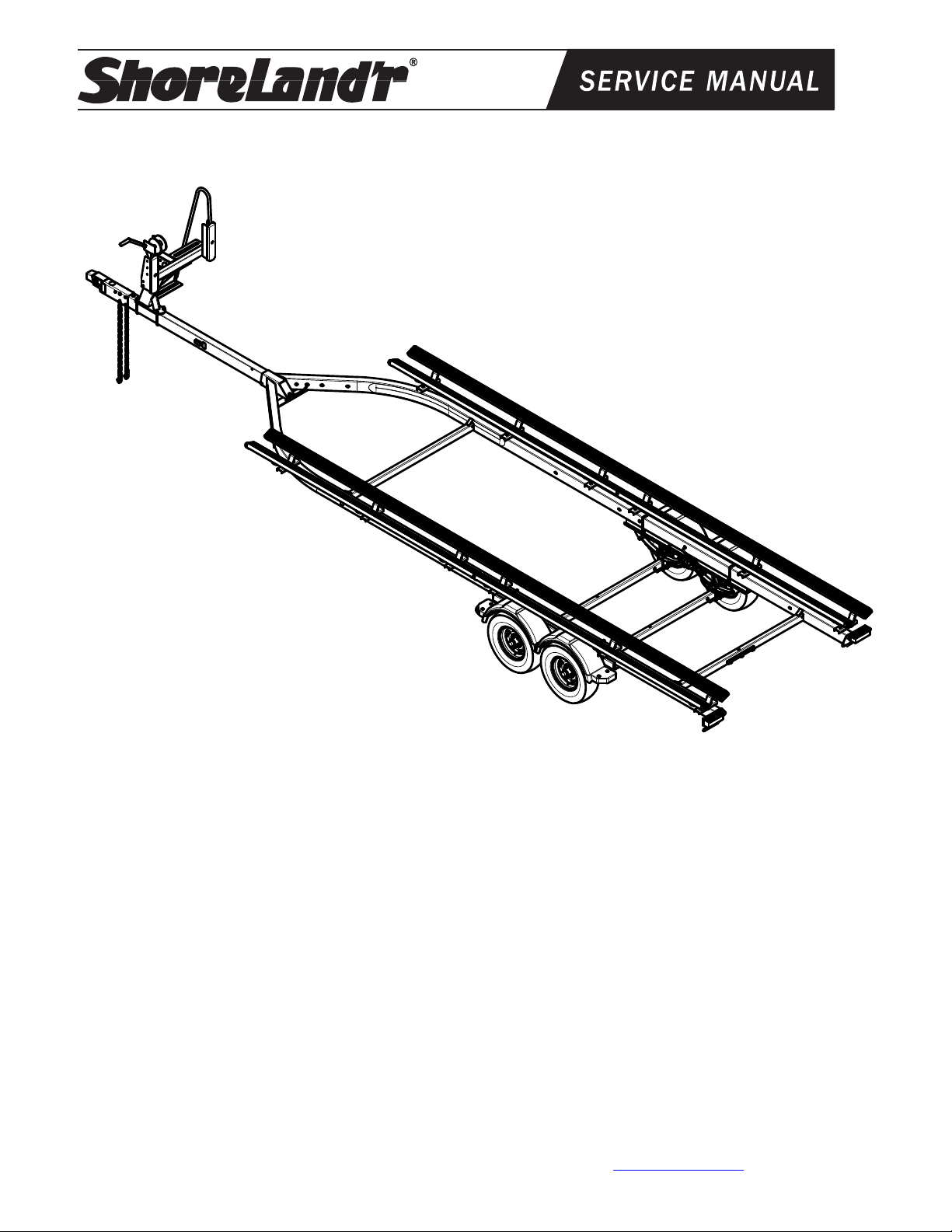
Pontoon Trailer W/Plastic Covered Bunks
PT2555TABBP
PT2555TABBP Pontoon Trailer
69352 Brake Kit Tandem Axle Conn. Hose
69082 Lit Packet – Brake Trailers
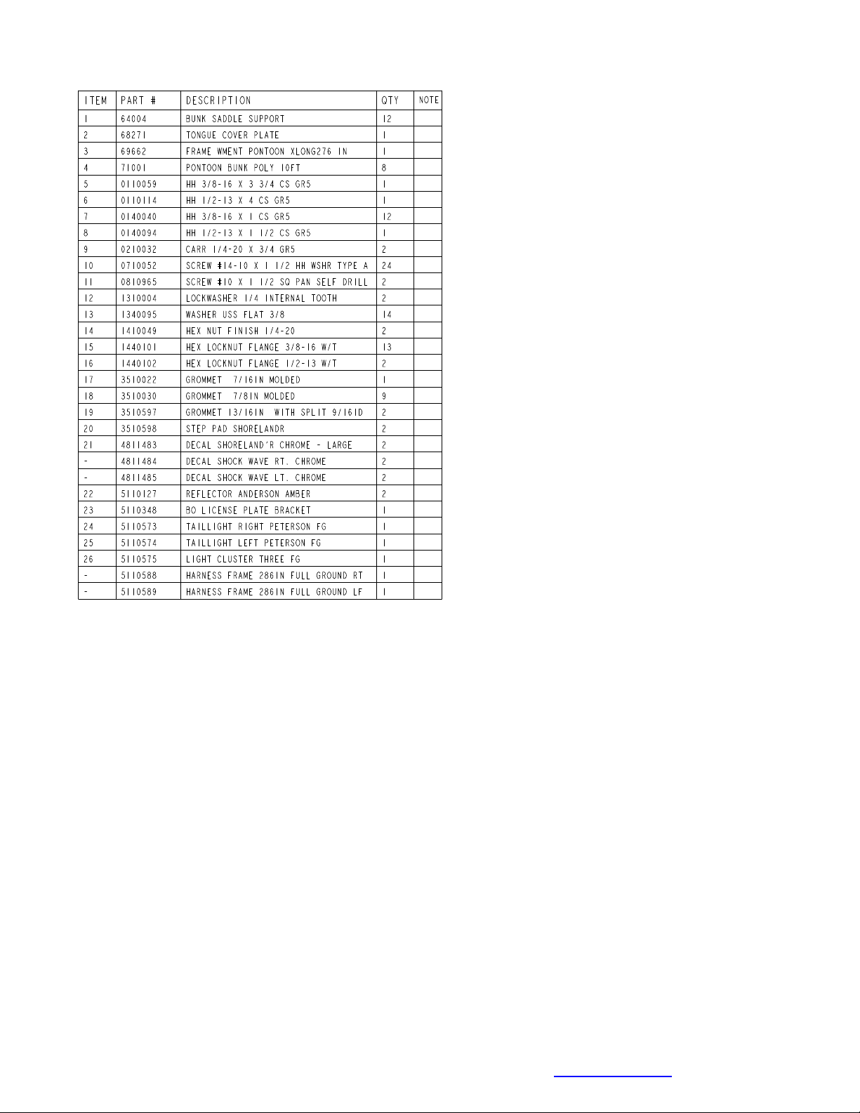
80844_ _ Frame Bundle - PT2555TABBP
* ST185/80D13-D Tire/Galv Rim
69677-_ _ Tongue Assy 90” Pontoon Disc
*Check with your dealer/customer service representative for current tire/rim
assembly part number.
ShoreLand’r offers its product line in painted finishes.
When ordering parts, it is important that you specify the
finish or color you have on your product. The 5-digit
number along with a 2-digit space _ _, note that the
parts can be purchased in various finishes.
00........ Galvanized
Tire Size and Carrying Capacity Chart
Tire Size.............................ST185/80D13-D
GVWR................................6840 lb.
Carrying Capacity.............5500 lb.
Axle....................................Tandem (2 Brake)
Refer to the tire side wall for correct tire
pressure. NOTE: Brakes available as optional
equipment.
Midwest Industries, Inc. Ida Grove, IA 51445 800-859-3028 www.shorelandr.com 0004356
Page 1 of 10 4/08/2011
Page 2
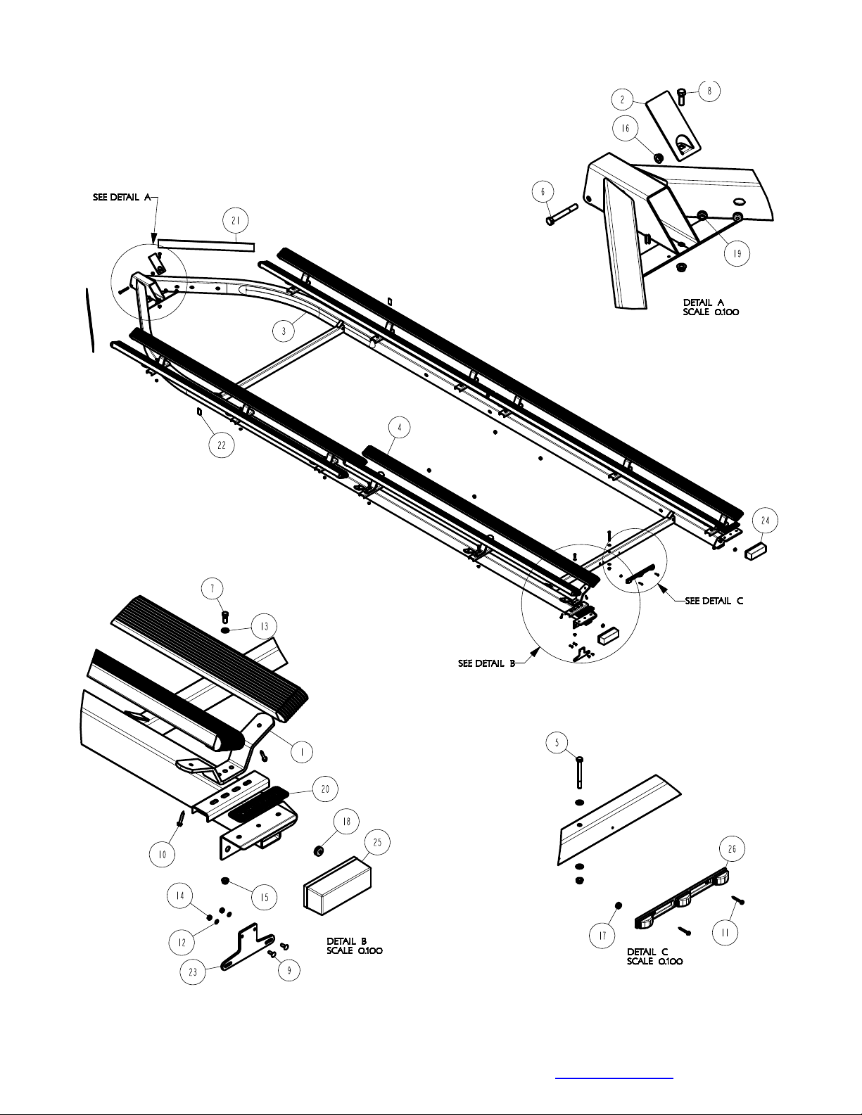
Remove the small parts from the frame by cutting the banding. Remove the bolt bag and sort all the
nuts and bolts by size.
Midwest Industries, Inc. Ida Grove, IA 51445 800-859-3028 www.shorelandr.com 0004356
Page 2 of 10 4/08/2011
Page 3
.
SIDE MARKER LIGHTS FOR TONGUE
Note: When installing the tongue in the trailer,
the side marker lights will have to be mounted to
the tongue. They are shipped in a bag that is
attached to the tongue. Insert the wire harness
from the side marker light into the larger hole in
the side of the tongue, then route the wire
harness to the rear of the tongue. Attach the
bezel with the rivets provided. Plug the side
marker light into the two female ends of the wire
harness just pulled through on the large side
hole. Snap the light assembly into the bezel.
Repeat on the other side marker light.
Secure the tongue into the frame by placing a
1/2” x 4” cross bolt in the front of the tongue
channel. Locate the tongue cover plate. Feed
the wire harness and brake line if applicable
through the hole in the tongue cover plate.
Position the tongue cover plate so the mounting
hole aligns with the hole in the rear bottom of
the tongue. Place a 1/2” x 1 1/2” hex bolt
downward through the tongue cover plate,
tongue and tongue channel. Secure both
mounting bolts with 1/2 flange lock nuts.
Tighten.
Plug the tongue wire harness ends into the
frame harnesses by matching colors and ends.
Push the excess wire provided into the rear of
the tongue or else remove the grommet in the
side frame and place the excess wire in the side
frame. Replace grommet just removed.
SAFETY CHAINS
Insert a 1/2” x 5” hex bolt through a 1/2” flat washer and then into the end link of one safety chain.
Insert the bolt into the open hole in the actuator and tongue and out the other side. Place the end link of
other safety chain then a 1/2” flat washer on the bolt and secure with a 1/2” flange lock nut. Tighten.
Midwest Industries, Inc. Ida Grove, IA 51445 800-859-3028 www.shorelandr.com 0004356
Page 3 of 10 4/08/2011
Page 4

Midwest Industries, Inc. Ida Grove, IA 51445 800-859-3028 www.shorelandr.com 0004356
Page 4 of 10 4/08/2011
Page 5

WINCH POST
Position the winch post on the tongue and
secure in place using 1/2” x 3 9/16” x 6”
square U-bolts. Secure with 1/2” flange lock
nuts. Tighten only to hold in position
because they will have to be moved when
the pontoon is placed on the trailer.
Attach the winch handle to the winch using
the nylon locking nut provided on the winch.
Midwest Industries, Inc. Ida Grove, IA 51445 800-859-3028 www.shorelandr.com 0004356
Page 5 of 10 4/08/2011
Page 6

SPRINGS
Position the axle under the frame so it is
properly orientated. Note position in drawing.
Place the springs on top of the axle as shown
so the closed eye of the spring is to the front
of the trailer. Place a spring clamp on top of
the springs then drop two 1/2´x 2 5/16´x 6 1/2”
square U-bolts over the clamp and the spring
as shown.
Align the legs of the U-bolt with the holes in
the spring plate slide it up against the axle.
Secure with 1/2” flange lock nuts. Tighten to
keep all items in position but do not securely
tighten until the axle assembly is completely
installed under the frame.
Midwest Industries, Inc. Ida Grove, IA 51445 800-859-3028 www.shorelandr.com 0004356
Page 6 of 10 4/08/2011
Page 7

Midwest Industries, Inc. Ida Grove, IA 51445 800-859-3028 www.shorelandr.com 0004356
Page 7 of 10 4/08/2011
Page 8

TIRE AND WHEEL ASSEMBLIES
Mount the tire and wheel assemblies using
the 1/2” fine threaded tapered lug nuts
provided. Tighten to 85-95 ft/lb. of torque
using the rotation pattern as shown in the
ShoreLandr’s Owners Manual. Re-torque
the lug nuts after 50 miles of driving and then
periodically thereafter.
AXLE
Place one of the spring bracket bushings into
the rear of the spring bracket and secure with
a 9/16” x 3 1/4” hex bolt and hex lock nut.
Repeat in other spring bracket. Position the
axle under the frame, then hook the loop end
of the spring around the bushings just
installed.
Note that if the axle is positioned too low
when trying to hook, the loops will not hook
around the bushings.
Raise the front of the springs up so they align
with the front hole of the spring bracket.
Secure in place with 9/16” X 3-1/4” hex bolts
and lock nuts. Repeat this process on the
other spring.
Tighten all axle U-bolts and spring bolts not
tightened at this time.
Midwest Industries, Inc. Ida Grove, IA 51445 800-859-3028 www.shorelandr.com 0004356
Page 8 of 10 4/08/2011
Page 9

BUNKS
Note that the bunk system is adjustable for width to fit most center dimensions of the pontoon tubes.
Determine the centers of the bunk support system that fits the pontoon tubes for the pontoon that is
going to be placed on the trailer and position accordingly.
Position the Plastic covered bunks so end of the bunk is approximately even with the taillight. Attach
the bunks to the brackets using the 1/4” x 1 1/2” lag screws provided. Position the second bunk so it is
just to the front of the rear bunk just installed.
Repeat this process on the bunks on the other side of the bunk saddle support and then on the other
side of the trailer
Midwest Industries, Inc. Ida Grove, IA 51445 800-859-3028 www.shorelandr.com 0004356
Page 9 of 10 4/08/2011
Page 10

ADJUSTING INSTRUCTIONS
Place the pontoon on the trailer so that the
pontoon tubes are flush with the ends of the
bunks. This will give you maximum support. The
bunk spacing has already been determined and
set for width when the trailer was assembled.
WINCH POST
With the pontoon in its proper position, slide the
winch post assembly backward until it contacts
the deck. The plastic stops allow for the
variance in most deck heights. It is adjustable
up or down approximately 3” if required. This is
accomplished by loosening and removing the
two bolts that attach the top of the winch post
assembly to the base.
Once the winch post is contacting the deck,
tighten in position. Hook the winch strap into the
bow eye and tighten by cranking the winch.
AXLE ADJUSTMENT
The amount of tongue weight on your trailer can
be adjusted as follows:
To lower the tongue weight, adjust the axle
assembly forward. To increase the tongue
weight, adjust the axle assembly backward.
The distance that the axle assembly has to be
moved will vary because it is directly related to
the weight and center of gravity of the boat
placed on it.
Best towing is achieved when the tongue weight
is 5-7% of the total gross load of the complete
unit.
Recheck all fasteners on the complete trailer to
make sure they are all tight and ready for
towing. All fasteners should be periodically
checked before towing.
See your ShoreLand’r Owner’s Guide for
further technical information regarding your
trailer and its components.
Midwest Industries, Inc. Ida Grove, IA 51445 800-859-3028 www.shorelandr.com 0004356
Page 10 of 10 4/08/2011
 Loading...