

Page 1
®
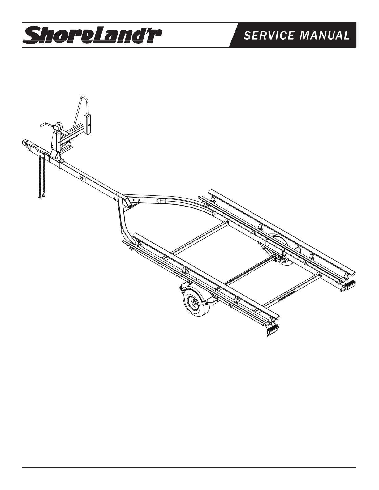
PT1922B
Pontoon Trailer
PT1922B Pontoon Trailer
69082 Lit Packet - Trailers - Brakes
69890 Brake First Axle Hose Kit 8” Disc
80612-_ _ Frame Bundle - PT1922B
*20.5X8x10E Tire/Rim
69677-_ _ Tongue Assy 90” Pontoon Disc
*Check with your dealer/customer service representative for current tire/rim assembly part number.
ShoreLand’r offers its product line in painted nishes. When
ordering parts, it is important that you specify the nish or
color you have on your product. The 5-digit number along
with a 2-digit space _ _, note that the parts can be purchased
in various nishes.
00........ Galvanized
03........ Black
Midwest Industries, Inc. Ida Grove, IA 51445 800.859.3028 www.shorelandr.com 0003930
Page 1 03/19/2008
Tire Size and Carrying Capacity Chart
Tire Size ............................20.5X8x10E
GVWR ...............................3040 lb.
Carrying Capacity ............2200 lb.
Axle ...................................Single Axle Brake
Refer to the tire side wall for correct tire pressure.
Page 2
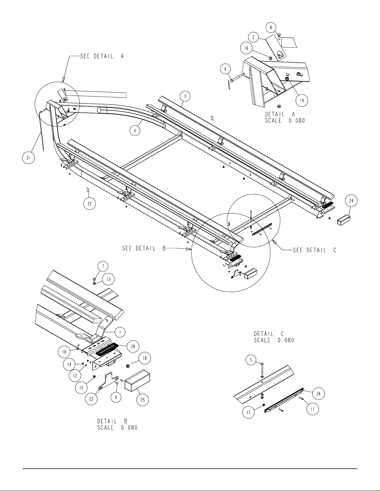
Diagram A
Midwest Industries, Inc. Ida Grove, IA 51445 800.859.3028 www.shorelandr.com 0003930
Page 2 03/19/2008
Page 3
SIDE MARKER LIGHTS FOR TONGUE
Note: When installing the tongue in the trailer, the side marker
lights will have to be mounted to the tongue. They are shipped in a
bag that is attached to the tongue. Insert the wire harness from the
side marker light into the larger hole in the side of the tongue, then
route the wire harness to the rear of the tongue. Attach the bezel
with the rivets provided. Plug the side marker light into the two female ends of the wire harness just pulled through on the large side
hole. Snap the light assembly into the bezel. Repeat on the other
side marker light.
Secure the tongue into the frame by placing a ½” x 4” cross bolt in
the front of the tongue channel. Locate the tongue cover plate as
shown in Diagram A, Detail A. Feed the wire harness and brake line
if applicable through the hole in the tongue cover plate. Position the
tongue cover plate so the mounting hole aligns with the hole in the
rear bottom of the tongue. Place a ½” x 1 ½” hex bolt downward
through the tongue cover plate, tongue and tongue channel. Se-
cure both mounting bolts with ½ ange lock nuts. Tighten.
Plug the tongue wire harness ends into the frame harnesses by
matching colors and ends. Push the excess wire provided either
into the rear of the tongue or else remove the grommet in the side
frame and place the excess wire in the side frame. Replace grommet just removed.
SAFETY CHAINS
Insert a 3/8” x 1 ¼” hex bolt through a 3/8” at washer and then into
the end link of one safety chain. Insert the bolt into the front bottom
hole punched in the tongue. Place another 3/8” at washer on the
bolt and secure with a 3/8” ange lock nut. Tighten.
Remove the small parts from the frame by cutting the banding. Remove the bolt bag and sort all the nuts and bolts by size.
BUNKS
Note that the bunk system is adjustable for width to t most center dimensions of the pontoon tubes. Determine the centers of the
bunk support system that ts the pontoon tubes for the pontoon
that is going to be placed on the trailer and position accordingly.
Position the carpeted bunks so approximately 10” extends past
the back of the rear bunk saddle support. Attach the bunks to the
brackets using the ¼” x 1 ½” lag screws provided. Position the second bunk so it is just to the front of the rear bunk just installed.
Repeat this process on the bunks on the other side of the bunk
saddle support and then on the other side of the trailer.
TONGUE
See Diagram B, Page 4.
Locate the proper length tongue. Insert the rear of the tongue into
the frame tongue channel until the mounting holes line up. Locate
the wire harness. Unwind and insert the end with the two plugs that
mate with the frame harness into the hole and route out the rear of
the tongue. Place a rubber grommet around the wire in the hole on
top of the tongue.
Repeat this process on the other safety chain.
BRAKE LINE
Locate the brass brake line coupling. Remove the plastic cap and
thread the brake line coming out the rear of the tongue into one
end of the coupling. Bend the line in a smooth gradual radius being
careful not to kink the line. Bend so it can be mated to the brake
line from the side frame. Once aligned, thread the side frame brake
line into the other end of the coupling. Tighten both lines into the
coupling.
If brakes are going to be installed, the line should be installed inside
the tongue at this time.
Midwest Industries, Inc. Ida Grove, IA 51445 800.859.3028 www.shorelandr.com 0003930
Page 3 03/19/2008
Page 4

Diagram B
Midwest Industries, Inc. Ida Grove, IA 51445 800.859.3028 www.shorelandr.com 0003930
Page 4 03/19/2008
Page 5

Diagram C
WINCH POST
See Diagram C.
Position the winch post on the tongue and secure in place using
½” x 3 9/16” x 6” square U-bolts. Secure with ½” ange lock nuts.
Tighten only to hold in position because they will have to be moved
when the pontoon is placed on the trailer.
Attach the winch handle to the winch using the nylon locking nut
provided on the winch.
Midwest Industries, Inc. Ida Grove, IA 51445 800.859.3028 www.shorelandr.com 0003930
Page 5 03/19/2008
Page 6

Diagram D
Midwest Industries, Inc. Ida Grove, IA 51445 800.859.3028 www.shorelandr.com 0003930
Page 6 03/19/2008
Page 7

SPRINGS
See Diagram D.
Position the axle under the frame so it is properly orientated. All
2” x 2” pontoon axles have holes drilled for mounting brake lines.
These attaching holes must be positioned to the rear of the trailer.
(If a brake axle is being installed, make sure axle is oriented so the
brake backup plates are on the right sides of the trailer. (Right on
right and left of left.)
Place the springs under the axle as shown so the closed eye of the
spring is to the front of the trailer. Drop two ½´x 2 9/16´x 5” square
U-bolts down around the axle and on each side of the spring as
shown.
Align the legs of the U-bolt with the holes in a spring pad and then
insert so the spring pad is up against the spring. Secure with ½”
ange lock nuts. Tighten to keep all items in position but do not securely tighten until the axle assembly is completely installed under
the frame.
AXLE
Place one of the spring bracket bushings into the rear of the spring
bracket and secure with a 9/16” x 3 1/4” hex bolt and hex lock nut.
Repeat in other spring bracket. Position the axle under the frame,
then hook the loop end of the spring around the bushings just in-
ONE AXLE BRAKE INSTALLATION
Cut the tape securing the brake line hose to the axle. Place the
other end of the hose up through the hole provided in the brake line
clip bracket. Secure in place with the U-shaped hose clip provided.
Remove the brass plug from the end of the hose.
stalled. Note that if the axle is positioned too low when trying to
hook, the loops will not hook around the bushings.
Remove the plastic cap from the end of the frame brake line com-
ing out of the side frame by the axle. Carefully uncoil the brake line
Raise the front of the springs up so they align with the front hole
of the spring bracket. Secure in place with 9/16” X 3-1/4” hex bolts
and lock nuts. Repeat this process on the other spring.
Tighten all axle U-bolts and spring bolts not tightened at this time.
Midwest Industries, Inc. Ida Grove, IA 51445 800.859.3028 www.shorelandr.com 0003930
Page 7 03/19/2008
so that it will reach the end of the hose just attached to the brake
line bracket. Thread the brake line tting into the brake line hose.
Tighten.
DO NOT OVER TIGHTEN
Page 8

Refer to your ShoreLand’r Owner’s
Guide and other decals on trailer for
additional information.
SAFETY INSTRUCTIONS
4810709
Proper tongue weight must be maintained.
Rev C 8/28/06
Before towing, check the following to ensure
that:
1. All parts, bolts, nuts and wheel lug
nuts are tight.
2. All wheel lug nuts must be tightened
to a minimum torque rating of 85 ft/lb.
3. Lug nuts must be re-torqued after the
first 50 miles, then periodically there
after.
4. Tires are inflated to manufacturer’s
standards. (See tire sidewall)
5. Wheel bearings have adequate
grease.
6. Hitch ball is the proper diameter and
has a rating equal to or greater than
the GVWR of the trailer.
7. Coupler is properly attached and
secured to coupler ball.
8. Trailer safety chains are crossed
under the tongue and attached to
towing vehicle.
9. All lights are operational. Note: It is
recommended that the trailer lights
be disconnected before backing into
the water.
10. Tie downs, winch strap and bow eye safety chain are secure.
11. Trailer tongue jack is in up or travel
position.
NOTE: The axle has brake uid installed in the clusters and the
axle line when it is assembled at the factory. This is done to protect
the inner parts of the brake system during shipping and storage.
The complete brake system including the axle MUST be re-bled to
ensure that all air has been removed from the brake system.
Fill the actuator reservoir with brake uid and bleed the line per the
bleeding instructions in one of the following; UFP Brake Bleeding
Manual or the ShoreLand’r Disc Brake Manual. Rell the reser-
voir and replace the reservoir cap.
TIRE AND WHEEL ASSEMBLIES
Mount the tire and wheel assemblies using the ½” ne threaded
tapered lug nuts provided. Tighten to 85-95 ft/lb. of torque using the
rotation pattern as shown in the ShoreLandr’s Owners Manual.
Re-torque the lug nuts after 50 miles of driving and then periodically thereafter.
ADJUSTING INSTRUCTIONS
Place the pontoon on the trailer so that the pontoon tubes are ush
with the ends of the bunks. This will give you maximum support.
The bunk spacing has already been determined and set for width
when the trailer was assembled.
WINCH POST
With the pontoon in its proper position, slide the winch post assembly backward until it contacts the deck. The plastic stops allow
for the variance in most deck heights. It is adjustable up or down
approximately 3” if required. This is accomplished by loosening and
removing the two bolts that attach the top of the winch post assembly to the base.
Once the winch post is contacting the deck, tighten in position.
Hook the winch strap into the bow eye and tighten by cranking the
winch.
AXLE ADJUSTMENT
The amount of tongue weight on your trailer can be adjusted as
follows:
To lower the tongue weight, adjust the axle assembly forward. To
increase the tongue weight, adjust the axle assembly backward.
The distance that the axle assembly has to be moved will vary because it is directly related to the weight and center of gravity of the
boat placed on it.
Best towing is achieved when the tongue weight is 5-7% of the total
gross load of the complete unit.
Recheck all fasteners on the complete trailer to make sure they are
all tight and ready for towing. All fasteners should be periodically
checked before towing.
See your ShoreLand’r Owner’s Guide for further technical information regarding your trailer and its components.
Midwest Industries, Inc. Ida Grove, IA 51445 800.859.3028 www.shorelandr.com 0003930
Page 8 03/19/2008
 Loading...