

Page 1
®
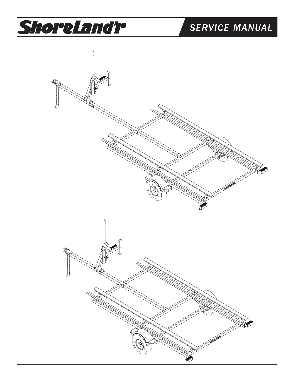
PT1720 & PT1420 Pontoon Trailer
PT1720 Pontoon Trailer
70275 Hdwe Box Pontoon PT1420/1720
62340 Lit Packet - Trailers
80672__ Frame Bundle - PT1720
*20.5X8X10E Tire/Rim
70260__ Tongue Assy Pontoon 3X3X174IN
*Check with your dealer/customer service representative for current tire/rim assembly part number.
PT1420 Pontoon Trailer
70275 Hdwe Box Pontoon PT1420/1720
62340 Lit Packet - Trailers
80673__ Frame Bundle - PT1420
*20.5X8X10E Tire/Rim
70261__ Tongue Assy Pontoon 3X3X138IN
*Check with your dealer/customer service representative for current tire/rim assembly part number.
ShoreLand’r offers its product line in painted nish-
es. When ordering parts, it is important that you spec-
ify the nish or color you have on your product. The
5-digit number along with a 2-digit space _ _, note
that the parts can be purchased in various nishes.
00........ Galvanized
03........ Black
Midwest Industries, Inc. Ida Grove, IA 51445 800.859.3028 www.shorelandr.com 0004034
Page 1 Rev C 05/13/2010
Page 2
Midwest Industries, Inc. Ida Grove, IA 51445 800.859.3028 www.shorelandr.com 0004034
Page 2 Rev C 05/13/2010
Page 3
Remove the small parts from the frame by cutting the banding. Remove the bolt bag and sort all the nuts and bolts by size.
the pontoon that is going to be placed on the trailer and position
accordingly.
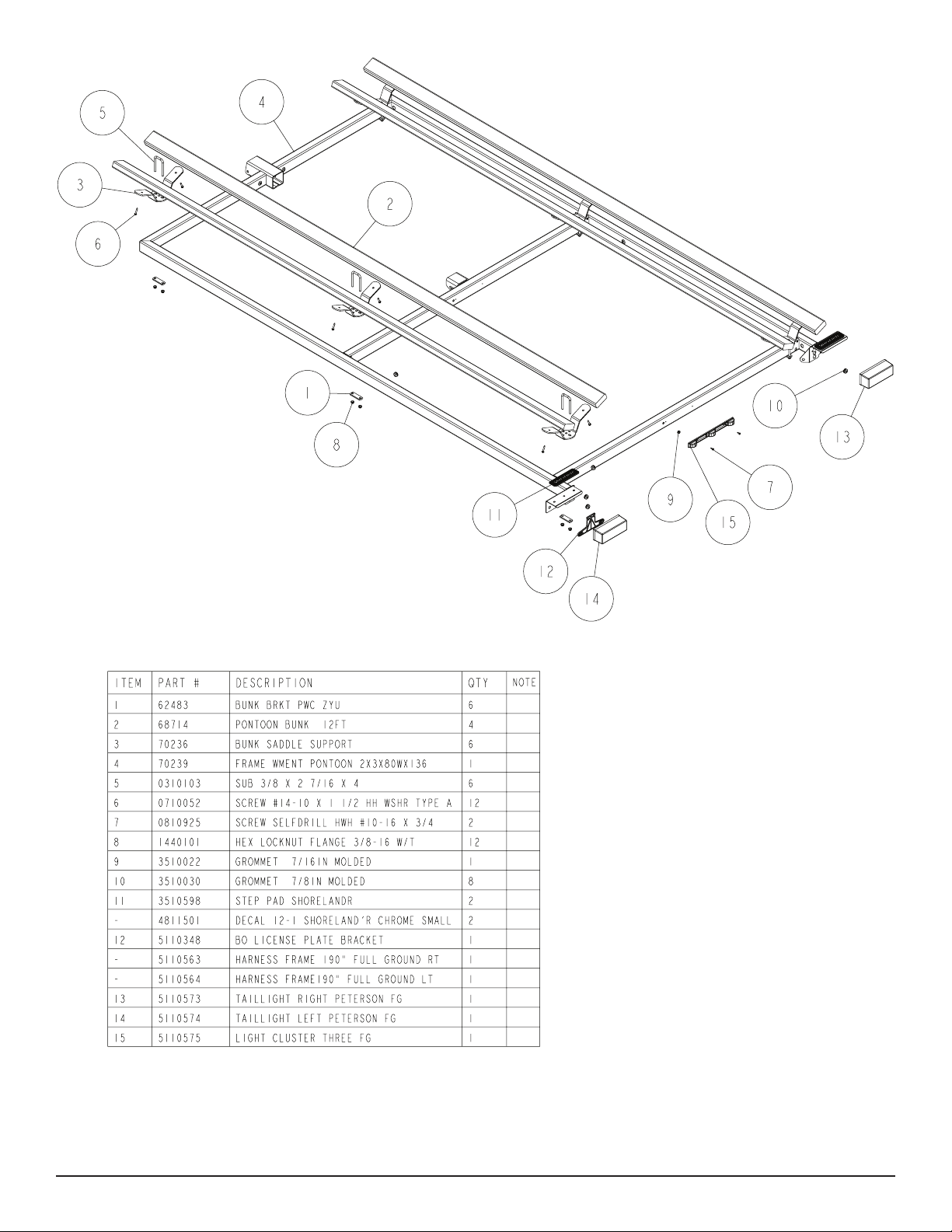
BUNKS
Note that the bunk system is adjustable for widths up to 76” to
t most center dimensions of the pontoon tubes. Determine the
centers of the bunk support system that ts the pontoon tubes for
Place the bunk saddle bracket on the crossmember with the arms
of the bracket parallel to the crossmember. Insert a 3/8 x 2 7/16 x
4 square u-bolt into the holes on the bracket so that the legs of the
u-bolt are on each side of the crossmember. Place item #1 over the
legs of the u-bolt on the bottom of the crossmember and secure
with 3/8” ange locknuts. Do not tighten at this time. Repeat this
process for the remaining bunk saddle brackets.
Now determine the center point of the crossmembers dividing the
center to center dimension in half. Measuring from the center point
of the crossmember to the u-bolt on the bunk saddle brackets
sliding them in or out till dimension is aquired. Secure brackets in
place. Repeat on the remaning brackets.
Midwest Industries, Inc. Ida Grove, IA 51445 800.859.3028 www.shorelandr.com 0004034
Page 3 Rev C 05/13/2010
Page 4

Position the carpeted bunks so approximately 10” extends past
the back of the rear bunk saddle support. Attach the bunks to the
brackets using the ¼” x 1 ½” lag screws provided.
Repeat this process on the bunk on the other side of the bunk saddle support and then on the other side of the trailer.
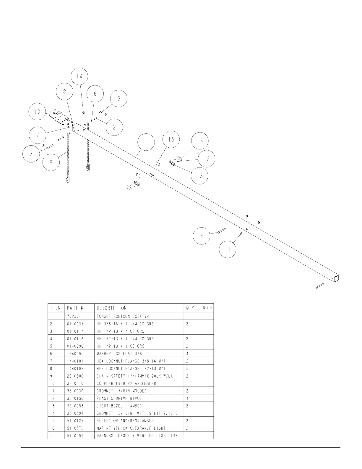
TONGUE
See Page 4 (assembly for PT1720) and Page 5 (assembly for
PT1420)
Once the proper tongue is identied place it on the stands so it can
be prepared for installation into the frame. Locate the two amber
side marker lights shipped in the hardware box. Uncoil the wire
insert the plug into the larger, center hole that is drilled in the side
of the tongue. As the wire is inserted into the hole direct the wire so
it will go to the forward end of the tongue. Pull the wire out the front
of the tongue. It will be connected to the tongue harness at a later
time. Attach the light to the tongue using two (2) No. 10 x 3/4” self
tapping screws provided. Repeat this process on the other light on
Midwest Industries, Inc. Ida Grove, IA 51445 800.859.3028 www.shorelandr.com 0004034
Page 4 Rev C 05/13/2010
Page 5

the other side of the tongue.
COUPLER
Locate the proper length tongue. Insert the rear of the tongue into
the frame tongue channel sliding it thru until it slides into the mounting channel on the second crossmember until the mounting holes
line up. Secure the tongue into the frame by placing a ½” x 4 1/4”
Locate the coupler. Drop it into position on the front of the tongue.
Secure it to the tongue using a ½” x 4” hex bolt through the rear
mounting hole of the coupler housing. Insert completely through
the tongue, then secure in place with a ½” ange lock nut.
hex bolt in the front tongue channel and the channel on the second
crossmember. Secure both mounting bolts with ½ ange lock nuts.
Tighten.
Locate the wire harness that is in the tongue. Plug the tongue wire
harness ends into the frame harnesses by matching colors and
Attach the front of the coupler to the tongue using two- ½” x 1” hex
bolts. Insert the bolt through one side of the coupler housing and
the tongue. Secure inside the tongue using a ½” ange lock nut.
Repeat this process on the other side of the tongue. Tighten all at-
taching bolts securely.
ends. Push the excess wire provided either into the side of the
tongue or else remove the grommet in the front crossmember and
insert the excess wire. Replace grommets just removed.
Midwest Industries, Inc. Ida Grove, IA 51445 800.859.3028 www.shorelandr.com 0004034
Page 5 Rev C 05/13/2010
Page 6

SAFETY CHAINS
Insert a 3/8” x 1 ¼” hex bolt through a 3/8” at washer and then into
the end link of one safety chain. Insert the bolt into the front bottom
hole punched in the tongue. Place another 3/8” at washer on the
bolt and secure with a 3/8” ange lock nut. Tighten.
Repeat this process on the other safety chain.
WINCH POST.
Position the winch post on the tongue and secure in place using ½”
x 3 9/16” x 3 7/8” square U-bolts. Secure with ½” ange lock nuts.
Tighten only to hold in position because they will have to be moved
when the pontoon is placed on the trailer.
Attach the adjustable bow stop section to the winch post using
three 3/8” X 3 3/4” Carriage bolts and securing with 3/8” ange lock
Midwest Industries, Inc. Ida Grove, IA 51445 800.859.3028 www.shorelandr.com 0004034
Page 6 Rev C 05/13/2010
Page 7

Midwest Industries, Inc. Ida Grove, IA 51445 800.859.3028 www.shorelandr.com 0004034
Page 7 Rev C 05/13/2010
Page 8

Tire Size and Carrying Capacity Chart
Tire Size ............................20.5X8X10E
GVWR ...............................2960 lb.
Carrying Capacity ............2000 lb.
Axle ...................................Single
Refer to the tire side wall for correct tire pressure.
NOTE: Brakes available as optional equipment.
Midwest Industries, Inc. Ida Grove, IA 51445 800.859.3028 www.shorelandr.com 0004034
Page 8 Rev C 05/13/2010
Page 9

Refer to your ShoreLand’r Owner’s
Guide and other decals on trailer for
additional information.
SAFETY INSTRUCTIONS
4810709
Proper tongue weight must be maintained.
Rev C 8/28/06
Before towing, check the following to ensure
that:
1. All parts, bolts, nuts and wheel lug
nuts are tight.
2. All wheel lug nuts must be tightened
to a minimum torque rating of 85 ft/lb.
3. Lug nuts must be re-torqued after the
first 50 miles, then periodically there
after.
4. Tires are inflated to manufacturer’s
standards. (See tire sidewall)
5. Wheel bearings have adequate
grease.
6. Hitch ball is the proper diameter and
has a rating equal to or greater than
the GVWR of the trailer.
7. Coupler is properly attached and
secured to coupler ball.
8. Trailer safety chains are crossed
under the tongue and attached to
towing vehicle.
9. All lights are operational. Note: It is
recommended that the trailer lights
be disconnected before backing into
the water.
10. Tie downs, winch strap and bow eye safety chain are secure.
11. Trailer tongue jack is in up or travel
position.
nuts. Note the three sets of holes in the very front of the bow stop
bracket. Place two of the three bolts in the top & bottom sets of
holes. The bolt in the top set of holes may be moved to the center
holes in the event that the bow stop needs to be adjusted higher.
This will have to be adjusted to meet the bow of the boat.
Attach the winch handle to the winch using the nylon locking nut
provided on the winch.
SPRINGS
Position the axle under the frame so it is properly orientated. All
axles have holes drilled for mounting brake lines. These attaching
holes must be positioned to the rear of the trailer.
Place the springs on the axle as shown so the closed eye of the
spring is to the front of the trailer. Drop two ½´x 2 9/16´x 6 1/2”
square U-bolts down over the spring clamp and over the springs
and on each side of the axle as shown.
Align the legs of the U-bolt with the holes in a spring pad and then
secure with ½” ange lock nuts. Tighten to keep all items in position
but do not securely tighten until the axle assembly is completely
installed under the frame.
AXLE
Place one of the spring bracket bushings into the rear of the spring
bracket and secure with a 9/16” x 3 1/4” hex bolt and hex lock nut.
Repeat in other spring bracket. Position the axle under the frame,
then hook the loop end of the spring around the bushings just installed. Note that if the axle is positioned too low when trying to
hook, the loops will not hook around the bushings.
Raise the front of the springs up so they align with the front hole
of the spring bracket. Secure in place with 9/16” X 3-1/4” hex bolts
and lock nuts. Repeat this process on the other spring.
Tighten all axle U-bolts and spring bolts not tightened at this time.
TIRE AND WHEEL ASSEMBLIES
Mount the tire and wheel assemblies using the ½” ne threaded
tapered lug nuts provided. Tighten to 85-95 ft/lb. of torque using the
rotation pattern as shown in the ShoreLandr’s Owners Manual.
Re-torque the lug nuts after 50 miles of driving and then periodically thereafter.
ADJUSTING INSTRUCTIONS
Place the pontoon on the trailer so that the pontoon tubes are ush
with the ends of the bunks. This will give you maximum support.
The bunk spacing has already been determined and set for width
when the trailer was assembled.
WINCH POST
With the pontoon in its proper position, slide the winch post assembly backward until it contacts the deck. The plastic stops allow
for the variance in most deck heights. It is adjustable up or down
if required. This is accomplished by loosening the three bolts that
attach the top winch post assembly to the winch base.
Once the winch post is contacting the deck, tighten in position.
Hook the winch strap into the bow eye and tighten by cranking the
winch.
AXLE ADJUSTMENT
The amount of tongue weight on your trailer can be adjusted as
follows:
Midwest Industries, Inc. Ida Grove, IA 51445 800.859.3028 www.shorelandr.com 0004034
Page 9 Rev C 05/13/2010
To lower the tongue weight, adjust the axle assembly forward. To
increase the tongue weight, adjust the axle assembly backward.
The distance that the axle assembly has to be moved will vary be-
cause it is directly related to the weight and center of gravity of the
boat placed on it.
Best towing is achieved when the tongue weight is 5-7% of the total
gross load of the complete unit.
Recheck all fasteners on the complete trailer to make sure they are
all tight and ready for towing. All fasteners should be periodically
checked before towing.
See your ShoreLand’r Owner’s Guide for further technical information regarding your trailer and its components.
 Loading...