

Page 1
®
PS8X17TB & PS8X17TBB
Powersport - 4000 lb. Capacity
Bundles Required - PS8X17TB
1 69082 Literature Packet - Brake Trailer
1 8064003 Frame Bundle -PS8X17
4 *
1 7008303 Axle Assembly - Electric Brake
1 6762503 Axle Assembly - Non Brake
1 5110618 Harness Tonge 7-Pin/Battery/Box
*Check with your dealer/customer service representative for current tire/rim assembly part number.
ST185/80D13-C Bias Tire/TS Dir Rim
Tongue Weight Adjustment
Approximate Tongue Weight for Best Towing.
NOTE: Axle is adjustable. Shift load to obtain proper tongue
weight. Tongue weight should be 5-7% of total gross weight of the
trailer and load combined.
Tire Size & Carrying Capacity Chart
Tire Load Carrying
Size Range Capacity
ST185/80D13 C 1480 lbs.
Bundles Required - PS8X17TBB
1 69082 Literature Packet - Brake Trailer
1 8064003 Frame Bundle -PS8X17
4 *
2 7008303 Axle Assembly - Electric Brake
1 5110618 Harness Tonge 7-Pin/Battery/Box
*Check with your dealer/customer service representative for current tire/rim assembly part number.
Midwest Industries, Inc. Ida Grove, IA 51445 800.859.3028 www.shorelandr.com 0004005
Page 1 Rev D 08/08/2011
ST185/80D13-C Bias Tire/TS Dir Rim
Refer to tire side wall for correct tire pressure.
Page 2
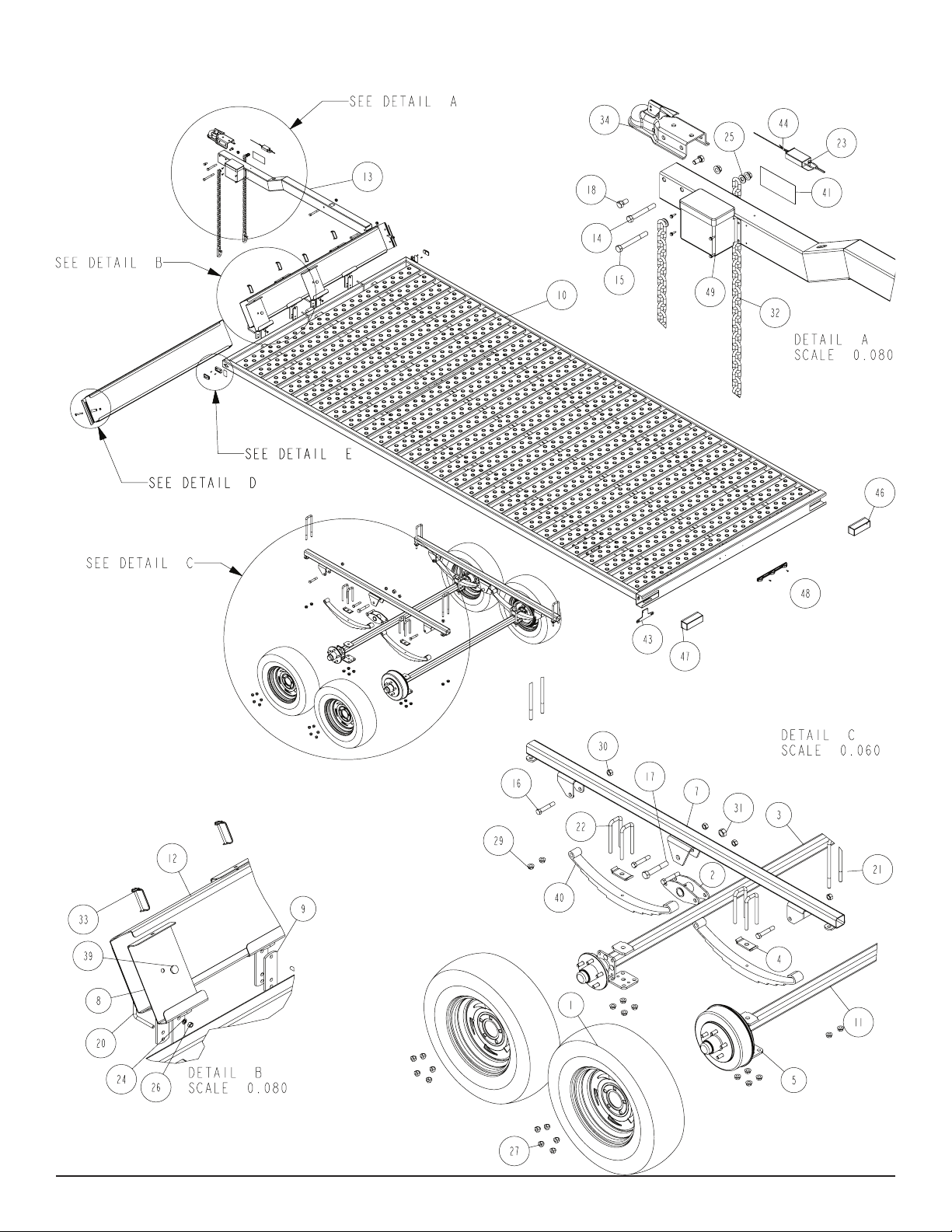
FRAME SETUP for PS8X17TB
Midwest Industries, Inc. Ida Grove, IA 51445 800.859.3028 www.shorelandr.com 0004005
Page 2 Rev D 08/08/2011
Page 3
Midwest Industries, Inc. Ida Grove, IA 51445 800.859.3028 www.shorelandr.com 0004005
Page 3 Rev D 08/08/2011
Page 4
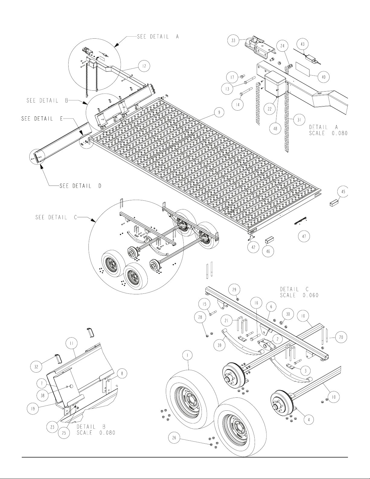
FRAME SETUP for PS8X17TBB
Midwest Industries, Inc. Ida Grove, IA 51445 800.859.3028 www.shorelandr.com 0004005
Page 4 Rev D 08/08/2011
Page 5

Midwest Industries, Inc. Ida Grove, IA 51445 800.859.3028 www.shorelandr.com 0004005
Page 5 Rev D 08/08/2011
Page 6

Standard Non Brake Axle
Midwest Industries, Inc. Ida Grove, IA 51445 800.859.3028 www.shorelandr.com 0004005
Page 6 Rev D 08/08/2011
Page 7

Electric Brake Assembly
Midwest Industries, Inc. Ida Grove, IA 51445 800.859.3028 www.shorelandr.com 0004005
Page 7 Rev D 08/08/2011
Page 8

FINAL ASSEMBLY INSTRUCTIONS
Remove the hardware bag from the frame, remove all parts and sort by
size.
TONGUE
Locate the tongue and the tongue wire harness. Thread the wire harness
into the slotted hole in the drop section of the tongue and then route the
wires out the hole in the top of the tongue midway to the rear. The seven
prong plug and the breakaway switch will remain out the front of the
tongue and will be addressed later.
between deck planks 7 and 8. Raise one of the spring brackets up into
position and place the rear mounting holes of the spring bracket over the
legs of the U-bolt just installed. Thread on ½” lock nuts to hold in position. Place the front mounting U-bolts (nine planks forward of the U-bolt
just installed) over the center frame mating it with the front mounting
holes of the spring bracket. Attach it with ½” lock nuts as well. Tighten
the spring bracket securely to the center frame.
Repeat this process on the other spring bracket.
TANDEM BOGIE
Locate the tandem bogies shown in Detail C. Note that the center bushing has a grease zerk in it. Position the tandem bogie up into the center
channel welded in the center of the tandem spring bracket so that the
grease zerk is pointing down. Align the holes in the channel with the
tandem bogie. Secure in place with a 3/4” x 4-1/2” hex bolt and lock
nut. Tighten. Repeat this process on the other tandem bogie and spring
bracket. Grease the bogie at this time by applying grease through the
zerk just discussed.
NOTE: The grease zerk is positioned down so that it is accessible for
servicing when needed.
SPRINGS
Position the axles so they are properly aligned with the trailer. The brake
axle backing plates are marked with white letters ”L” or “R” identifying
them as Left or Right so they can be mounted under the trailer correctly.
When standing behind the trailer, your Left is the trailers Left and your
Right is the trailers Right. It is very important that the axle is placed in
the correct orientation to function properly.
Place the springs on the topside of the spring pads welded to the axle.
(See chassis diagram). Note that the hook end of the spring must be to
the rear of the axle. Place a spring clamp on the top center of the spring
as shown. Next place the 1/2” x 5 ¾” U-bolts down over the top of the
spring clamp, spring and axle as shown.
Place the spring and axle U-bolt plate onto the legs of the two U-bolts
just positioned. Secure in place with 1/2” lock nuts. Thread onto the Ubolts but do not tighten securely until the complete unit is in position on
the trailer. Repeat on the other spring.
Position the tongue assembly under the front of the trailer in its approximate installed position. Remove the wire harness plugs from the trailer
frame. Mate the mating plugs so the wires colors match in each plug.
Note that the 2 two wire mating plugs are for the electric brakes and are
interchangeable.
Once all plugs are mated place all excess wire into the tongue. Raise
the tongue up into the mounting channels of the trailer frame. Secure in
position with ½” x 4” hex bolts and ange lock nuts. Tighten.
SAFETY CHAINS
Locate the 1/2” x 4” hex bolt. Slip the bolt through a 1/2” at washer,
then place through the last link of one of the safety chains. Insert the bolt
through the mating holes provided in the hole in the tongue for mounting
the safety chains. Place a second safety chain and at washer on the bolt
on the opposite side of the tongue. Secure with a 1/2” ange lock nut.
Tighten.
TANDEM AXLE SPRING BRACKETS
The undercarriage for the tandem trailer can be adjusted forward or
backward to best suit your need. The location suggested in these instructions is satisfactory for most applications.
Locate the ½” x 2 9/16” x 9” U-bolts supplied. Counting from the rear
cross member, drop one of the U-bolts down over the center frame tube
Repeat this process on the front axle.
AXLE
Place one of the spring bracket bushings into the rear of the spring bracket and secure with a 9/16” x 3-1/4” hex bolt and hex lock nut. Repeat in
other spring bracket.
Raise the rear axle into position up under the spring brackets. Hook the
loop of the springs around the bushings just installed. Note that if the
axle is positioned too low when trying to hook, the loops will not hook
around the bushings. Raise the front of the springs up so they align with
the rear hole in the tandem bogie just installed. Secure in place with
9/16” x 3-1/4” hex bolts and lock nuts.
Install another spring bracket bushing in the front hole on the tandem
bogie assemblies. Secure with a 9/16” x 3-1/4” hex bolt and lock nut.
Tighten. Hook the hook end of the springs mounted to the front axle over
the bushing just installed in the rocker arm assembly. Swing the front of
the spring up and attach the front mounting hole in the spring bracket
with an¬other 9/16” x 3-1/4” hex bolt and lock nut.
Tighten all axle U-bolts and spring bolts.
ELECTRIC BRAKE SYSTEM
Note there are brake wires routed out of the holes located on the inside
of the center frame tube close to the axle positions. Remove the tape
securing the wires to the center frame. Route them down to the wires
coming out of the rear of the brake backing plate.
Midwest Industries, Inc. Ida Grove, IA 51445 800.859.3028 www.shorelandr.com 0004005
Page 8 Rev D 08/08/2011
Page 9

BATTERY BOX
Locate the section of shrink wrap material and wire connectors that are
provided in the brake kit. Place a shrink wrap section over the wires
before splicing them together. Connect the wires to each other using
the crimp connectors provided. Once the connections have been made,
center the shrink wrap material over the splices. Using a heat gun heat
the shrink wrap material until it is shrunk down and creates a water tight
seal over the connections.
Place all excess wire into the center frame tube and insert the rubber
grommet.
Repeat this process on the brake on the other side of the trailer.
Repeat this process on the second axle brakes.
BREAKAWAY SWITCH
Place the breakaway switch on the tongue harness so it is located behind
the decal on the top of the tongue. Align the mounting hole in the
breakaway switch with the hole pre-drilled in the tongue at this location.
Secure the breakaway switch to the tongue using the self-tapping screw
provided.
Locate the battery box. Position it on the side of the tongue aligning the
holes in the battery box with the pre-drilled mating holes in the side of
the tongue. Secure in place using four (4) self-tapping screws provided.
Midwest Industries, Inc. Ida Grove, IA 51445 800.859.3028 www.shorelandr.com 0004005
Page 9 Rev D 08/08/2011
Page 10

Place the battery inside the battery box. Route the section of the wire
harness over to the battery and connect it to the battery using the connector spades of the wire harness. Connect the Red wire to the positive
terminal and the white wire to the negative terminal. The battery will
maintain its charge when it is connected to the tow vehicle and is used
only in the event the trailer becomes disconnected from the tow vehicle.
In the event it does become disconnected the pin will be removed from
the breakaway switch allowing the battery to power the brakes causing
them to stop and trailer and hold it in position for up to twenty minutes
after disconnect.
TIRE & WHEEL ASSEMBLY
Mount the tire and wheel assemblies using the 1/2” ne threaded tapered
lug nuts provided. Tighten to 85-95 ft./lb. torque using the rotation pattern as shown in the ShoreLandr’s Owners Manual.
Re-torque the lug nuts after 50 miles driving and then periodically
thereafter.
Front Ramp Kit
The front ramp kit is designed to attach to the front cross frame tube
of the PS5x10, PS5x14, and the PS8x17 series. The kit includes
the ramps and all attaching hardware for converting the ramps into
a front shield while being stored for transport. The ramp retainer
channels are designed to accommodate U-bolts for attaching them
to either a 2x3” or 2x4” frame tube.
Installing the ramps in the following manner will allow for the removal of the ramp from the *left side of the trailer rst.
*Left and Right side of trailer is indicated by standing at the
rear of the trailer.
Installation Instructions
• Locate the four ramp retainer attachment channels. Note that
they are all identical.
• The two ramp retainer attachment channels on the *right side
of the trailer will be installed on the front side of the trailer front
frame tube so it will support the ramp as shown.
• Note that the kit is supplied with two different size U-bolts. Select the proper size to t your frame tube. Place one of the
correct size square U-bolt around the front frame tube so the
legs of the U-bolt are pointing forward. Align the holes in one of
the ramp retainer attachment channels with the U-bolt legs, then
slide into position. Note that this channel is mounted on the
front side of the frame tube. Secure in place with 3/8” lock
washers and 3/8” hex nuts.
• Position the U-bolt so it is 24” from the outside of the side
frame tube.
• Repeat the mounting process on the second channel. Position
this ramp retainer attachment channel so that the center hole
in the ramp retainer bracket is 27” from the center hole in the
ramp retainer channel just installed. Tighten enough to hold in
position until the ramp is installed for nal spacing.
• Install the remaining two ramp retainer attachment channels
on the left side of the trailer to the rear side of the front frame
tube using the steps above. Placing them on the rear of the
frame tube allows the ramps to overlap past each other in the
middle.
• Once all four of the ramp retainer attachment channels are at-
tached to the frame, position the right ramp into the ramp retainer attachment channels. The ramp can either be slid into
the end of the channels or else placed in the approximate position, then rotated into place.
Midwest Industries, Inc. Ida Grove, IA 51445 800.859.3028 www.shorelandr.com 0004005
Page 10 Rev D 08/08/2011
Page 11

• Align the holes provided in the edge of the ramp with the holes
in the center of the ramp retainer attachment channels as
follows:
Place one of the ¼” pins with the wire retainer through the •
aligned holes in the ramp and the retainer attachment channel.
Align the hole in the second ramp retainer attachment channel •
with the second hole in the ramp. Note that the U-bolt may
have to be loosened so the ramp retainer attaching channel
can be moved either direction to align the holes. When aligned,
insert a second ¼” pin with wire retainer. Once the pin is in-
serted, retighten the U-bolt just loosened to adjust for proper
hole spacing. The two pins will secure the ramps in the transport position.
Special Instructions:
Always check lighting and turn signal operations before towing.
Secure or tie-down your load before towing.
To prevent damage to your ATV trailer, tighten all fasteners before
towing.
Your ATV traile r is equi pped with a tota lly groun ded wir e
harness. You must be sure the wire harness plug that comes from
the tow vehicle is grounded to the tow vehicle using the white
grounding wire.
Check all lug nuts for proper torque before towing.
• Note the (right) passenger side ramp must always be installed
rst.
• Repeat the above process on the second ramp on the (left)
drivers side of the trailer.
There are two carriage bolts and plastic bushing supplied in •
the kit. These bushing, when mounted on the ramp, will keep
the ramps from moving either inward or outward when loading your machine. The bushings will extend down between the
deck planks to eliminate the side movement during loading.
Mount the bushing to the end of the ramp that attaches to the
trailer side frame. The bushing can be installed in one of three
positions to create the appropriate spacing width for loading
your machines.
• Installation is complete. The ramps can now be stored secure-
ly during the towing process and can be easily removed for
either loading or unloading the machines.
Using The Ramps
• Always remove the ramp that is on the *left side of the
trailer rst. The ramps are removed from its normal trans-
port position by removing the two ¼” retainer pins that attach
the ramp to the ramp retainer attachment channels.
Contact your authorized ShoreLand’r dealer if you experi-
ence a problem with your trailer. To locate a dealer, please use
www.shorelandr.com - the dealer locator feature.
For more information or assistance, contact ShoreLand’r at 1-800859-3028 or visit www. shorelandr.com.
• Once the pins are removed, rotate the ramp backward on top
to remove it from the ramp retainer attachment channels.
• Place the hook end of the ramp over the side frame tube or
the rear tube of the trailer deck so the hook end catches over
the inside top of the tube. This will secure it in place while loading the machine.
• Repeat the above process on the second ramp. Space the
ramps to mate the wheel centers of the machine.
• Once the machines are loaded and the ramps are ready for
storage, place them in the ramp retainer attachment channels
using a reverse process of removing them.
Midwest Industries, Inc. Ida Grove, IA 51445 800.859.3028 www.shorelandr.com 0004005
Page 11 Rev D 08/08/2011
 Loading...