

Page 1
®
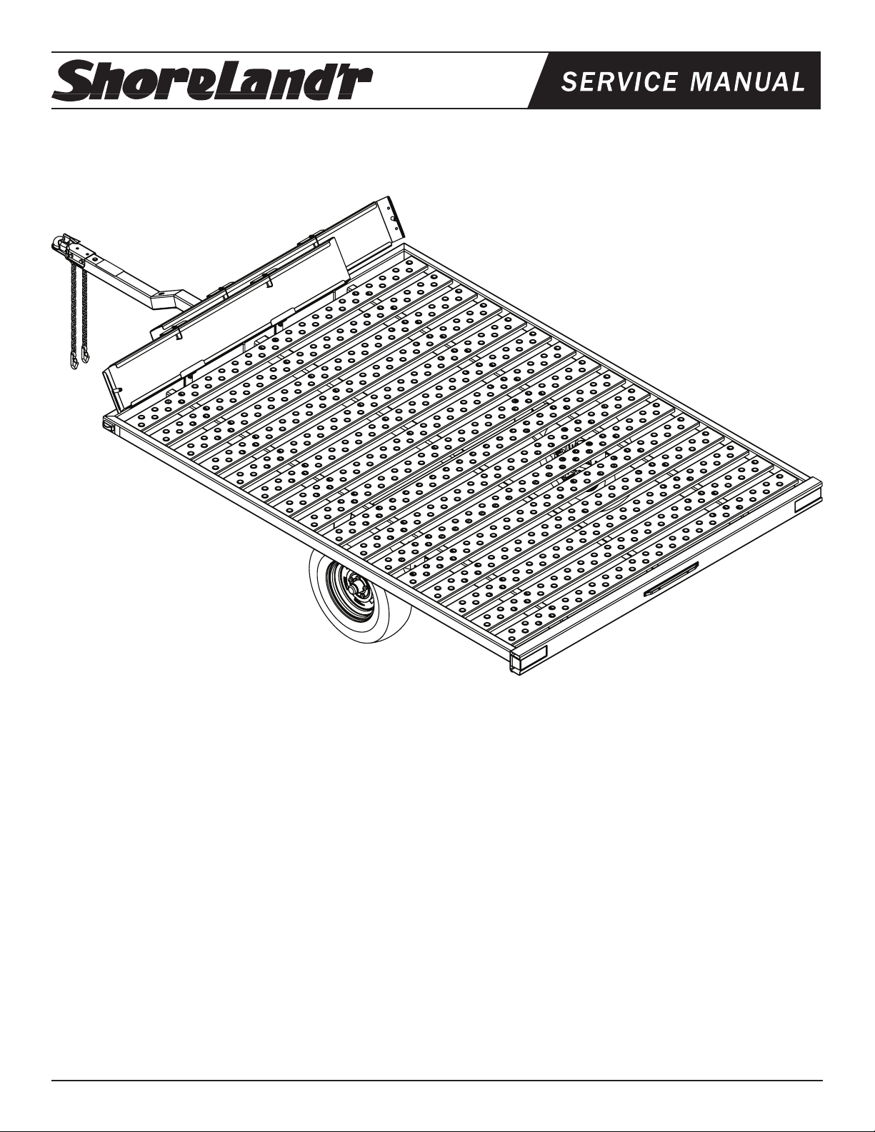
PS8X10
Powersports - 2100 lb. Capacity
Bundles Required - PS8X10
1 65069 Literature Packet - SL Powersports
1 8063403 Frame Bundle -PS8X10
2 *
*Check with your dealer/customer service representative for current tire/rim assembly part number.
ST185/80D13-C Bias Tire/TS Dir Rim
Tongue Weight Adjustment
Approximate Tongue Weight for Best Towing.
NOTE: Axle is adjustable. Shift load to obtain proper tongue
weight. Tongue weight should be 5-7% of total gross weight of the
trailer and load combined.
Tire Size & Carrying Capacity Chart
Tire Load Carrying
Size Range Capacity
ST185/80D13 C 1480 lbs.
Refer to tire side wall for correct tire pressure.
Midwest Industries, Inc. Ida Grove, IA 51445 800.859.3028 www.shorelandr.com 0004002
Page 1 10/01/2008
Page 2
Midwest Industries, Inc. Ida Grove, IA 51445 800.859.3028 www.shorelandr.com 0004002
Page 2 10/01/2008
Page 3

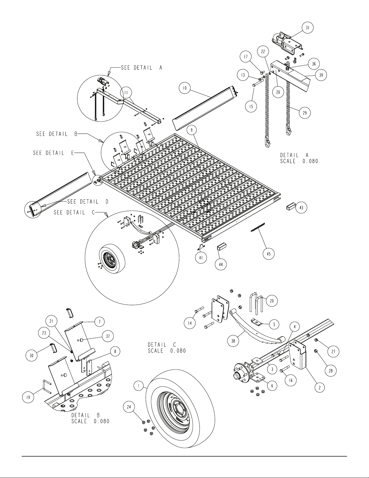
Assembly Instructions:
Cut all banding and sort hardware bags.
Lay the PS8X10 on the saw horses (recommendation) to
assemble.
Run the tongue wire harness through the tongue routing the wires
up through the hole in the top of the tongue. Place the tongue in
its proper location with respect to the frame. Mate the plugs on the
tongue wire harness with the frame harnesses, connect together
making a positive connection. All excess wire is to be placed inside
the tongue.
Raise the tongue into the two (2) tongue channels on the frame
and secure with two (2) 1/2” X 4-1/2” hex bolts and two (2)
1/2” ange lock nuts. Tighten.
See Detail A.
Insert a 3/8” X 1-1/ 4” hex bolt with a 3/8” flat washer an d
safety chain through the lower hole on the front of the tongue.
Se cu re wit h a 3/ 8” fla t wa sh er and 3/8 ” fl an ge loc k nu t.
Repeat assembly on opposite side of the tongue.
Mount the coupler to the tongue using two (2) 1/2” X 1” hex bolts in
the front holes and one (1) 1/2” X 4” hex bolt in the rear hole of the
coupler. Secure the 1/2” ange lock nuts.
AXLE ASSEMBLY:
Remove the spring channels from the axle. Attach the spring channels to the side frame using 1/2” X 3” hex bolts and secure with 1/2”
ange lock nuts.
Place the other 1/2” X 3” hex bolt into the spring channel and through
the frame. Secure with 1/2” ange lock nuts.
NOTE: 13” Tire - Bottom hole on spring channel
In the rear spring channel place the spring bracket bushing (Ref.#4) into specific hole location, refer to the NOTE for
placement depending on tire size. Secure the spring bracket bushing to the spring channel using a 9/16” X 3-1/4” hex bolt and 9/16”
hex bolt.
Sl ide the hook end of the spr ing over th e sprin g bracket
bushing just installed.
Mount the other end of the spring to the spring channel using a
9/16” X 3-1/4” hex bolt and secure with a 9/16” hex nut. Do not over
tighten.
Mount the axle assembly to the leaf spring using two (2) 1/2” X
2-5/16” X 5-3/4” u-bolts, one (1) spring clamp and one (1) spring
plate. Secure with 1/2” ange lock nuts. Refer to the Detail C for
placement. Repeat on opposite side of the axle assembly.
Raise the axle assembly up under the leaf springs and align the pin
on the bottom side of the spring with the hole in the axle. Align the
holes in a spring plate with the legs of the U-bolts just placed around
the springs. Slide the spring plate onto the U-bolts and secure with
1/2” ange lock nuts. Repeat on the second spring on the opposite
side of the trailer.
Remove the stud thread protectors. Mount the tires to the hubs us-
Midwest Industries, Inc. Ida Grove, IA 51445 800.859.3028 www.shorelandr.com 0004002
Page 3 10/01/2008
Page 4

ing 1/2” lug nuts. Note the taper end of the nut must be towards the
rim. Hand tighten the lug nuts using the star pattern as described
in the owners guide. Use a torque wrench for the nal tightening of
the lug nuts. Torque to 85-95 ft. lbs. of torque. Recheck the torque
after 50 miles of use, then periodically thereafter.
Front Ramp Kit
The front ramp kit is designed to attach to the front cross frame tube
of the PS5x10, PS5x14, and the PS8x17 series. The kit includes
the ramps and all attaching hardware for converting the ramps into
a front shield while being stored for transport. The ramp retainer
channels are designed to accommodate U-bolts for attaching them
to either a 2x3” or 2x4” frame tube.
• Align the hole in the second ramp retainer attachment channel
with the second hole in the ramp. Note that the U-bolt may
have to be loosened so the ramp retainer attaching channel
can be moved either direction to align the holes. When aligned,
insert a second ¼” pin with wire retainer. Once the pin is in-
serted, retighten the U-bolt just loosened to adjust for proper
hole spacing. The two pins will secure the ramps in the transport position.
• Note the (right) passenger side ramp must always be installed
rst.
• Repeat the above process on the second ramp on the (left)
drivers side of the trailer.
Installing the ramps in the following manner will allow for the removal of the ramp from the *left side of the trailer rst.
*Left and Right side of trailer is indicated by standing at the
rear of the trailer.
Installation Instructions
• Locate the four ramp retainer attachment channels. Note that
they are all identical.
• The two ramp retainer attachment channels on the *right side
of the trailer will be installed on the front side of the trailer front
frame tube so it will support the ramp as shown.
• Note that the kit is supplied with two different size U-bolts. Select the proper size to t your frame tube. Place one of the
correct size square U-bolt around the front frame tube so the
legs of the U-bolt are pointing forward. Align the holes in one of
the ramp retainer attachment channels with the U-bolt legs, then
slide into position. Note that this channel is mounted on the
front side of the frame tube. Secure in place with 3/8” lock
washers and 3/8” hex nuts.
• Position the U-bolt so it is 24” from the outside of the side
frame tube.
• Repeat the mounting process on the second channel. Position
this ramp retainer attachment channel so that the center hole
in the ramp retainer bracket is 27” from the center hole in the
ramp retainer channel just installed. Tighten enough to hold in
position until the ramp is installed for nal spacing.
• Install the remaining two ramp retainer attachment channels
on the left side of the trailer to the rear side of the front frame
tube using the steps above. Placing them on the rear of the
frame tube allows the ramps to overlap past each other in the
middle.
There are two carriage bolts and plastic bushing supplied in •
the kit. These bushing, when mounted on the ramp, will keep
the ramps from moving either inward or outward when loading your machine. The bushings will extend down between the
deck planks to eliminate the side movement during loading.
Mount the bushing to the end of the ramp that attaches to the
trailer side frame. The bushing can be installed in one of three
positions to create the appropriate spacing width for loading
your machines.
• Installation is complete. The ramps can now be stored secure-
ly during the towing process and can be easily removed for
either loading or unloading the machines.
Using The Ramps
• Always remove the ramp that is on the *left side of the
trailer rst. The ramps are removed from its normal trans-
port position by removing the two ¼” retainer pins that attach
the ramp to the ramp retainer attachment channels.
• Once the pins are removed, rotate the ramp backward on top
to remove it from the ramp retainer attachment channels.
• Place the hook end of the ramp over the side frame tube or
the rear tube of the trailer deck so the hook end catches over
the inside top of the tube. This will secure it in place while loading the machine.
• Repeat the above process on the second ramp. Space the
ramps to mate the wheel centers of the machine.
• Once the machines are loaded and the ramps are ready for
storage, place them in the ramp retainer attachment channels
using a reverse process of removing them.
• Once all four of the ramp retainer attachment channels are at-
tached to the frame, position the right ramp into the ramp retainer attachment channels. The ramp can either be slid into
the end of the channels or else placed in the approximate position, then rotated into place.
• Align the holes provided in the edge of the ramp with the holes
in the center of the ramp retainer attachment channels as
follows:
Place one of the ¼” pins with the wire retainer through the •
aligned holes in the ramp and the retainer attachment channel.
Midwest Industries, Inc. Ida Grove, IA 51445 800.859.3028 www.shorelandr.com 0004002
Page 4 10/01/2008
Page 5

Diagram A
Midwest Industries, Inc. Ida Grove, IA 51445 800.859.3028 www.shorelandr.com 0004002
Page 5 10/01/2008
Page 6

Special Instructions:
Contact your authorized ShoreLand’r dealer if you experi-
Always check lighting and turn signal operations before towing.
Secure or tie-down your load before towing.
To prevent damage to your ATV trailer, tighten all fasteners before
towing.
Your ATV traile r is equi pped with a tota lly groun ded wir e
harness. You must be sure the wire harness plug that comes from
the tow vehicle is grounded to the tow vehicle using the white
grounding wire.
Check all lug nuts for proper torque before towing.
Midwest Industries, Inc. Ida Grove, IA 51445 800.859.3028 www.shorelandr.com 0004002
Page 6 10/01/2008
ence a problem with your trailer. To locate a dealer, please use
www.shorelandr.com - the dealer locator feature.
For more information or assistance, contact ShoreLand’r at 1-800859-3028 or visit www. shorelandr.com.
 Loading...