

Page 1
®
PS6X12SR
Powersports with Side Rail - 2200 lb. Capacity
Bundles Required - PS6X12SR
1 65069 Literature Packet - SL Powersports
1 8060303 Frame Bundle -PS6X12SR
2 *
1 6913903 Ramp Bundle
1 6977403 Hardware Box - Ramps
*Check with your dealer/customer service representative for current tire/rim assembly part number.
ST185/80D13-C Bias Tire/TS Dir Rim
Tongue Weight Adjustment
Approximate Tongue Weight for Best Towing.
NOTE: Axle is adjustable. Shift load to obtain proper tongue
weight. Tongue weight should be 5-7% of total gross weight of the
trailer and load combined.
Tire Size & Carrying Capacity Chart
Tire Load Carrying
Size Range Capacity
ST185/80D13 C 1480 lbs.
Refer to tire side wall for correct tire pressure.
Midwest Industries, Inc. Ida Grove, IA 51445 800.859.3028 www.shorelandr.com 0004001
Page 1 REV C 10/01/2008
Page 2
TONGUE
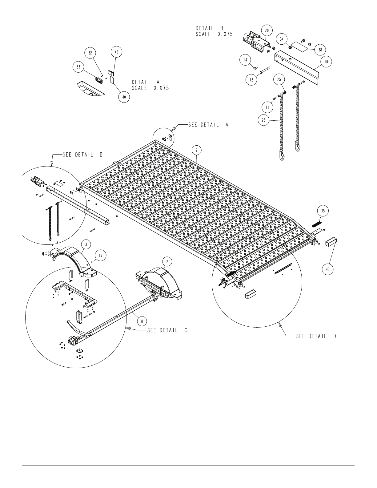
Refer to parts drawing on page 2 for placement.
Slide the tongue into the tongue channel on the frame assembly
and secure with two 1/2” X 4” hex bolts and 1/2” ange lock nuts.
ASSEMBLY INSTRUCTIONS:
FRONT STOP
SAFETY CHAIN
Refer to Diagram B on page 2 for placement.
Insert a 3/8” X 1-1/4” hex bolt with 3/8” at washer through the
safety chain. Insert this assembly through the lower hole on the
front of the tongue. Secure with a 3/8” at washer and 3/8” ange
lock nut on the inside of the tongue tube. Repeat this procedure on
the other side of the tongue tube.
Refer to Diagram A on page 2 for placement.
Mount the front stop weldment to the front of the frame using two
3/8” X 4-7/16” X 3” square u-bolts. The placement of the u-bolts will
go over the front frame tube weldment with the legs of the u-bolt
facing towards the inside of the frame. Secure with 3/8” at washers, 3/8” lock washers and 3/8” hex nuts. Insert black plastic caps
on exposed tube ends.
Midwest Industries, Inc. Ida Grove, IA 51445 800.859.3028 www.shorelandr.com 0004001
Page 2 REV C 10/01/2008
Page 3

SPRINGS
Refer to Diagram C for placement.
Mount the spring to the axle assembly using two 1/2” X 2-5/16”
X 6-1/2” square u-bolts over the spring clamp and spring. Secure
the spring to the axle assembly using a spring plate and four 1/2”
ange lock nuts. Repeat on opposite side of the axle assembly.
Install the spring bracket bushings and the 9/16” X 3-1/4” hex bolts
into the rear of the spring bracket (already attached to the frame).
Secure with 9/16” hex nuts. Hook the leaf spring on the axle assembly over the bushing just installed. Repeat this step on the opposite side of the axle assembly.
Insert a 9/16” x 3/14” hex bolt in the eye of the leaf spring and secure into the front spring bracket. Repeat on opposite side of the
axle assembly.
Midwest Industries, Inc. Ida Grove, IA 51445 800.859.3028 www.shorelandr.com 0004001
Page 3 REV C 10/01/2008
Page 4

Tighten all four bolts to secure the under carriage to the trailer.
Special Instructions:
TIRES
Remove the stud thread protectors. Mount the tires to the hubs
using 1/2” hex lug nuts. Tighten to 85-95 ft./lb. of torque using the
rotation pattern as shown in the ShoreLand’r Owner’s Guide.
Re torque the lug nuts after 50 miles of driving and then periodically
thereafter.
REAR RAMP - Optional - TA0142
Midwest Industries, Inc. Ida Grove, IA 51445 800.859.3028 www.shorelandr.com 0004001
Page 4 REV C 10/01/2008
Always check lighting and turn signal operations before towing.
Secure or tie-down your load before towing.
Contact your authorized ShoreLand’r dealer if you experience a problem with your trailer. To locate a dealer, please use
www.shorelandr.com - the dealer locator feature.
For more information or assistance, contact ShoreLand’r at 1-800859-3028 or visit www. shorelandr.com.
Page 5

Midwest Industries, Inc. Ida Grove, IA 51445 800.859.3028 www.shorelandr.com 0004001
Page 5 REV C 10/01/2008
Page 6

Midwest Industries, Inc. Ida Grove, IA 51445 800.859.3028 www.shorelandr.com 0004001
Page 6 REV C 10/01/2008
 Loading...