

Page 1
®
PS6X12
Powersports - 2200 lb. Capacity
Bundles Required - PS6X12
1 65069 Literature Packet - SL Powersports
1 8067103 Frame Bundle -PS6X12
2 *
*Check with your dealer/customer service representative for current tire/rim assembly part number.
ST185/80D13-C Bias Tire/TS Dir Rim
Tongue Weight Adjustment
Approximate Tongue Weight for Best Towing.
NOTE: Axle is adjustable. Shift load to obtain proper tongue
weight. Tongue weight should be 5-7% of total gross weight of the
trailer and load combined.
Tire Size & Carrying Capacity Chart
Tire Load Carrying
Size Range Capacity
ST185/80D13 C 1480 lbs.
Refer to tire side wall for correct tire pressure.
Midwest Industries, Inc. Ida Grove, IA 51445 800.859.3028 www.shorelandr.com 0003905
Page 1 REV B 09/23/2008
Page 2
ps6x12_2.pdf 9/23/2008 1:27:42 PM
TONGUE
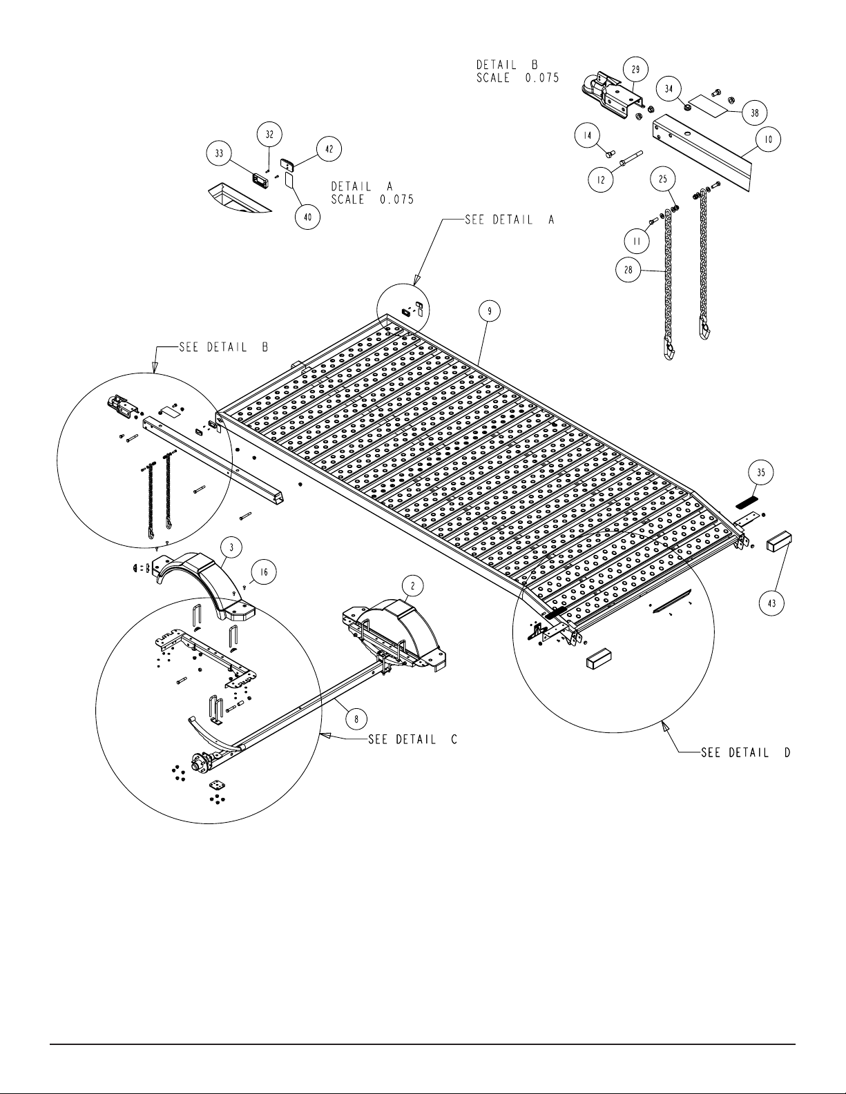
Refer to parts drawing on page 2 for placement.
Slide the tongue into the tongue channel on the frame assembly
and secure with two 1/2” X 4” hex bolts and 1/2” ange lock nuts.
ASSEMBLY INSTRUCTIONS:
FRONT STOP
SAFETY CHAIN
Refer to Diagram B on page 2 for placement.
Insert a 3/8” X 1-1/4” hex bolt with 3/8” at washer through the
safety chain. Insert this assembly through the lower hole on the
front of the tongue. Secure with a 3/8” at washer and 3/8” ange
lock nut on the inside of the tongue tube. Repeat this procedure on
the other side of the tongue tube.
Refer to Diagram A on page 2 for placement.
Mount the front stop weldment to the front of the frame using two
3/8” X 4-7/16” X 3” square u-bolts. The placement of the u-bolts will
go over the front frame tube weldment with the legs of the u-bolt
facing towards the inside of the frame. Secure with 3/8” at washers, 3/8” lock washers and 3/8” hex nuts. Insert black plastic caps
on exposed tube ends.
Midwest Industries, Inc. Ida Grove, IA 51445 800.859.3028 www.shorelandr.com 0003905
Page 2 REV B 09/23/2008
Page 3

SPRINGS
Refer to Diagram C for placement.
Mount the spring to the axle assembly using two 1/2” X 2-5/16”
X 6-1/2” square u-bolts over the spring clamp and spring. Secure
the spring to the axle assembly using a spring plate and four 1/2”
ange lock nuts. Repeat on opposite side of the axle assembly.
Install the spring bracket bushings and the 9/16” X 3-1/4” hex bolts
into the rear of the spring bracket (already attached to the frame).
Secure with 9/16” hex nuts. Hook the leaf spring on the axle assembly over the bushing just installed. Repeat this step on the opposite side of the axle assembly.
Insert a 9/16” x 3/14” hex bolt in the eye of the leaf spring and secure into the front spring bracket. Repeat on opposite side of the
axle assembly.
Midwest Industries, Inc. Ida Grove, IA 51445 800.859.3028 www.shorelandr.com 0003905
Page 3 REV B 09/23/2008
Page 4

Tighten all four bolts to secure the under carriage to the trailer.
Special Instructions:
TIRES
Remove the stud thread protectors. Mount the tires to the hubs
using 1/2” hex lug nuts. Tighten to 85-95 ft./lb. of torque using the
rotation pattern as shown in the ShoreLand’r Owner’s Guide.
Re torque the lug nuts after 50 miles of driving and then periodically
thereafter.
FRONT RAMP - Optional - TA0141
Midwest Industries, Inc. Ida Grove, IA 51445 800.859.3028 www.shorelandr.com 0003905
Page 4 REV B 09/23/2008
Always check lighting and turn signal operations before towing.
Secure or tie-down your load before towing.
Contact your authorized ShoreLand’r dealer if you experience a problem with your trailer. To locate a dealer, please use
www.shorelandr.com - the dealer locator feature.
For more information or assistance, contact ShoreLand’r at 1-800859-3028 or visit www. shorelandr.com.
Page 5

Midwest Industries, Inc. Ida Grove, IA 51445 800.859.3028 www.shorelandr.com 0003905
Page 5 REV B 09/23/2008
Page 6

• Locate the hardware bag. Sort all items by size. Remove the
two steel straps.
• Position the rear tailgate as shown in the drawing. Align the
side tubes of the tailgate with the mounting brackets on the
rear of the trailer.
• Insert a 9/16” x 3 ¼” hex bolt through the outer hole in the
mounting bracket on the trailer frame and then through the
rear tailgate as shown in the assembly view on page
2. Push completely through the hole on the inside of the
mounting bracket.
• Secure in place with a 9/16” hex lock nut.
• Repeat the above two steps on the other end of the rear tail-
gate.
• Once both bolts and nuts are installed, tighten the nuts until
a minimum of two threads are exposed through the nuts. The
nuts can be tightened farther if desired making sure they are
not overtightened. The rear tailgate must be allowed to tilt.
• Locate the two metal straps. Align the hole in one end of the
steel straps with the attaching pin welded to the side frame
as shown in the assembly view on page 2. Slide the steel
strap onto the pin and secure in place using the 3/16” x 1 ¼”
lynch pins.
• Rotate the rear tailgate up into the transport position. Align
the hole in the other end of the steel straps with the pin on the
rear tailgate, then slide into position.
• Secure in place using a 3/16” x 1 ¼” lynch pin. Repeat on the
other strap.
• The rear tailgate is now in its transport postion.
• To lower the rear tailgate, remove the lynch pins securing the
steel straps to the rear tailgate, slide the steel straps off of the
pins and then lower to the ground. The rear tailgate is now in
the loading position.
• Installation is complete.
Midwest Industries, Inc. Ida Grove, IA 51445 800.859.3028 www.shorelandr.com 0003905
Page 6 REV B 09/23/2008
 Loading...