

Page 1
®
PS4X6
Powersports ATV Trailer, 1000 lb. Capacity
Bundles Required
PS4X6 ATV Powersports - Black
1 65069 Literature Packet - SL Utility
1 6588303 Tongue Weldment - PS4X6
1 6830103 Frame Bundle -PS4X6
1 *
*Check with your dealer/customer service representative for current tire/rim assembly part
number.
16.5X6.5X8-C Tire/T-Slvr Rim
Tire Size & Carrying Capacity Chart
Tire Load Carrying
Size Range Capacity
16.5X 6.5X8 C 795 lbs.
Refer to tire side wall for correct tire pressure.
Table of Contents:
Assemblies and/or Options ...................................2
Tongue Weight Adjustment
Approximate Tongue Weight for Best Towing.
NOTE: Axle is NOT adjustable. Shift load to obtain proper
tongue weight. Tongue weight should be 5-7% of total gross
weight of the trailer and load combined.
Midwest Industries, Inc. Ida Grove, IA 51445 800.859.3028 www.shorelandr.com 0003620
Page 1 REV D 04/15/200
Decals ...................................................................2
Tools Required ......................................................2
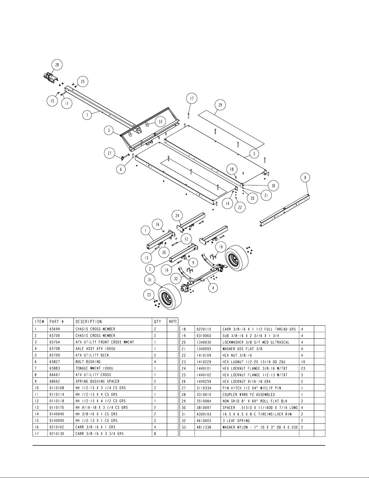
PS4X6 Bill of Material............................................ 2
PS4X6 Parts Drawing............................................ 3
PS4X6 Assembly Instructions ...............................4
SS1179 Stake Pocket Kit ......................................5
SS1181 Light Kit ....................................................6-8
Page 2
ASSEMBLIES AND/OR OPTIONS
6570803 Axle Assembly - ATV PS4X6
6570703 Hardware Bag - PS4X6
SS1181 Lite Kit for ATV Trailer
SS1179 ATV Stake Pocket Kit
Midwest Industries, Inc. Ida Grove, IA 51445 800.859.3028 www.shorelandr.com 0003620
Page 2 REV D 04/15/2008
Page 3
TOOLS REQUIRED FOR ASSEMBLY
3/4” Wrench/Socket
3/8” Wrench/Socket
5/16” Socket (sidelights)
9/16” Wrench/Socket
7/16” Wrench/Socket
Cable/Wire (to run harness/light
wires)
7/8” Wrench/Socket
13/16” Wrench/Socket
Optional equipment and replacement
parts must be purchased through an
authorized ShoreLand’r dealer.
Use saw horses to aid in the assembly.
Lay the deck ( with the deck side down)
on the saw horses.
NOTE: The decals should face the
ou tside of the ATV trailer. Decals
closest to the front will determine the
front of the trailer.
In the rear chassis cross weldments
in sert the spring bus hing spacer.
Secure the bushing to the chassis
cross weldments using 1/2” X 31/4” hex bolts and 1/2” flange lock
nuts.
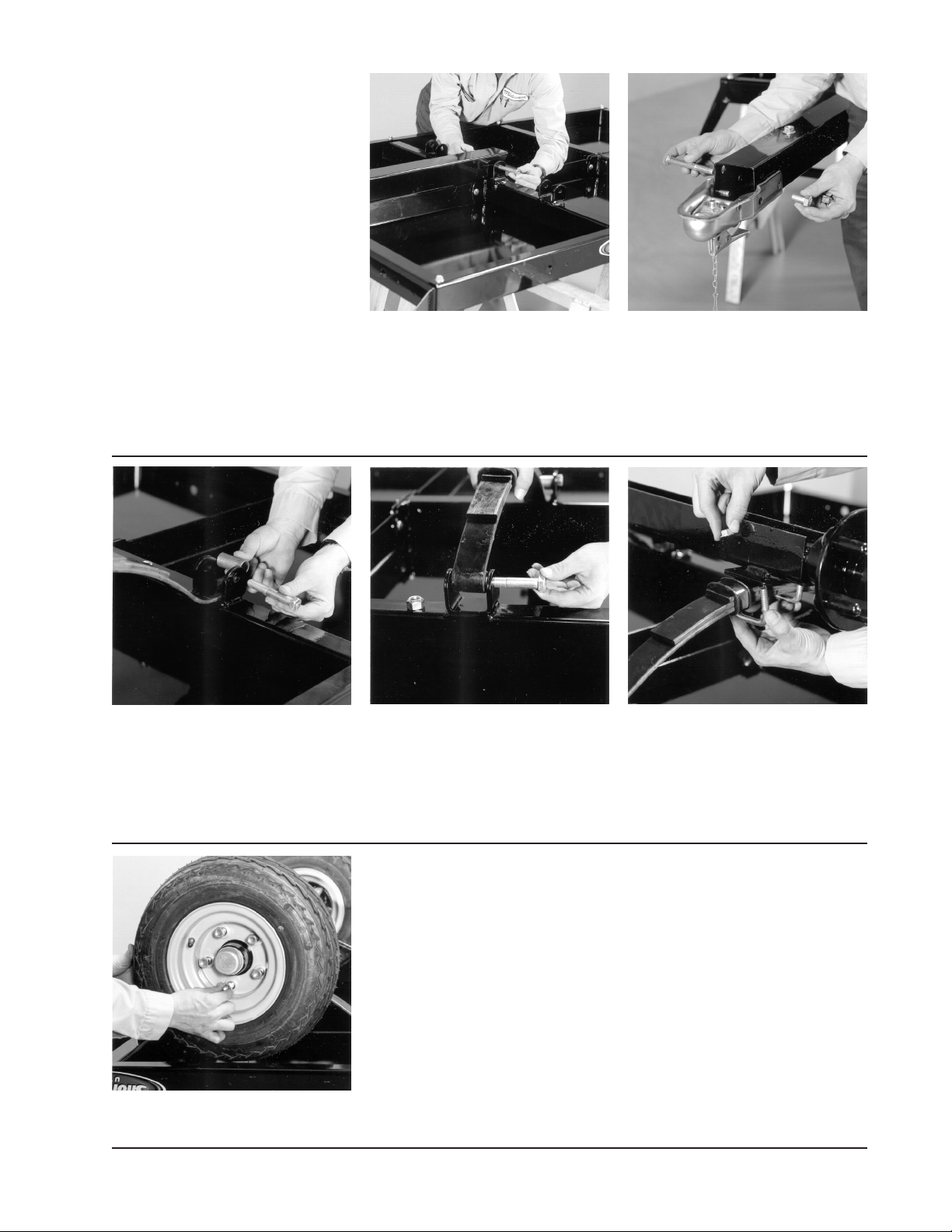
Slide the tongue into the front cross
weldment and secure with hitch pin
w/clip. In the rear of the tongue insert a
1/2” X 4-1/2” hex bolt and two (2) 1/2”
nylon washers (between tongue and
mounting plates). Secure with a 1/2”
ange lock nuts.
Slide the spring into the rear chassis cross weldment under the spring
bushing just installed. Insert the eye
of the spring in the front chassis cross
weldment and secure with the two (2)
remaining 9/16” X 3-1/4” hex bolts.
Tighten with 9/16” hex nuts.
Using a hoist or lifting device, lift your
ATV trailer off the saw horses and place
on it’s tires.
Mount the coupler to the tongue in the
two (2) top holes of the tongue using
one (1) 1/2” X 4” hex bolt in the rear
hole. Secure with a 1/2” ange lock nut.
Secure the front of the coupler to the
tongue using two (2) 1/2” X 1” hex
bolts. Secure with 1/2” flange lock
nuts.
Mount the axle assembly to the springs
just installed using the 3/8” X 2-3/16” X
1-3/4” SUB and secure with 3/8” ange
lock nuts.
If installing the light kit, install when trailer is upside down on the saw horses.
Double check all fasteners and tighten
before towing.
The ATV trailer is not highway or street
legal without the light kit being installed.
The light kit must be installed before
to wing on public highwa ys an d/or
streets!
Mount the tires to the axle assembly using 1/2” lug nuts. Tighten to secure.
Midwest Industries, Inc. Ida Grove, IA 51445 800.859.3028 www.shorelandr.com 0003620
Page 3 REV D 04/15/200
Page 4

Midwest Industries, Inc. Ida Grove, IA 51445 800.859.3028 www.shorelandr.com 0003620
Page 4 REV D 04/15/2008
Page 5

SS1179
Optional Stake Pocket Kit
Mount the stake pockets onto the pre-drilled holes on the frame of
your Powersports trailer using 1/4” X 3/4” hex bolts (Ref.#2) and
secure with a 1/4” ange lock nuts. (Ref.#3).
Side rail components can be purchased at your local lumber yard
or hardware store.
2X4 wood is recommended:
4 pc’s @ 74”
4 pc’s @ 43”
8 pc’s @12”
Midwest Industries, Inc. Ida Grove, IA 51445 800.859.3028 www.shorelandr.com 0003620
Page 5 REV D 04/15/200
Page 6

SS1181
Optional Light Kit
Midwest Industries, Inc. Ida Grove, IA 51445 800.859.3028 www.shorelandr.com 0003620
Page 6 REV D 04/15/2008
Page 7

Run the frame harness wires through
the hole on the to side of the tongue
when the trailer is in it’s normal upright
position. Push the wires to the rear of the
tongue and thread the wires through the
wire hole at the top side of the tongue in
it’s normal upright position. Place grommets in both wire holes.
Slide the wire tube into the rear cross
channel and through the chassis. Note
theat the two pre-drilled holes on the
wire tube must be inserted in rst as
shown. Thread the frame harness wires
just installed in the tongue into the wire
tube. Pull wires out the rear of the tube
so that the plugs are exposed.
Insert two (2) 1/8” x 1-1/2” cotter key
through the pre-drilled holes on the wire
tube as shown. Separate the legs of the
cotter key to secure.
Install molded grommets over the wires
to secure. Insert the wires in the hole
next to the wire tube.
In se rt t he side marker light wires
through the large pre-drilled hole in the
side of the tongue. Pull out the front of
the tongue. Mount the side marker light
Connect wires from the side marker
light to the plugs provided on the frame
harness - brown on brown.
to the tongue in the pre-drilled holes
using #10-16 X 3/4” self-drill screws as
shown.
Insert a 3/8” X 1-1/4 hex bolt with a 3/8”
at washer and safety chain through the
lower hole on the front of the tongue.
Secure with a 3/8” at washer and 3/8”
ange lock nut. Repeat procedure on
opposite side of the tongue. Loosen
and remove the rear hex nut holding
Place the taillight into the light channel
with the green/brown wiring and white
grounding wire fed through the wire hole
as shown.
Notice that the left taillight has the
yellow and brown wire. Slide the taillight
into the light channel. Install the license
plate bracket over the bolts on the
taillight. Attach to the rear crossmember
and secure with the hardware provided
with the taillight.
the coupler to the tongue and place the
white ground wire on the bolt threads.
Replace the nut and tighten.
Midwest Industries, Inc. Ida Grove, IA 51445 800.859.3028 www.shorelandr.com 0003620
Page 7 REV D 04/15/200
Page 8

When securing the taillight and bracket
to the rear crossmember, secure the
grounding wires before tightening.
Se cure th e w ire t ube t o t he rear
crossmember using a conduit clamp,
1/4” x 3/4” hex bolt and 1/4” ange lock
nut.
Tighten 1/4” ange lock nut to secure
the conduit clamp around the wire tube
as shown.
Insert the wire harness through the
plastic tube as shown.
Place a conduit clamp around the platic
tube.
Pull the wire harness thro ugh the
plastic tube as shown.
Secure to the inside of the rear crossmember using a 1/4” X 3/4” hex bolt and
1/4” ange lock nut.
Plug wire harness in.
AMERICAN STANDARDS FOR WIRING:
YELLOW - LEFT
GREEN - RIGHT
BROWN - RUNNING
WHITE - GROUNDING
Midwest Industries, Inc. Ida Grove, IA 51445 800.859.3028 www.shorelandr.com 0003620
Page 8 REV D 04/15/2008
 Loading...