

Page 1
MC2000-03 / MC2000A-03
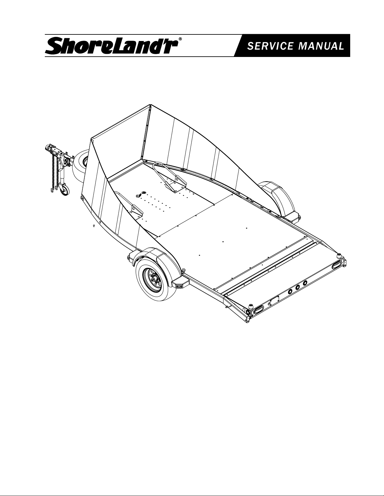
Motorcycle Trailer, V-Twin
MC2000-03 Motorcycle Trailer V-Twin
4300254
6845603 Frame Bundle MC V-Twin
3510039 Axle Dexter Torsion MC Trailer
6845703 Hardware Box MC V-Twin
65069 Lit Packet - ShoreLandʼr
3310050 Jack 800 lb. Swivel
ST215/75R14C GY OWL Mod Rim Chrome
MC2000A-03 Motorcycle Trailer V-Twin
4300227 ST215/75R14C GY OWL Alum Star Rim
6845603 Frame Bundle MC V-Twin
3510039 Axle Dexter Torsion MC Trailer
6845703 Hardware Box MC V-Twin
65069 Lit Packet - ShoreLandʼr Utility
3310050 Jack 800 lb. Swivel
Midwest Industries, Inc. Ida Grove, IA 51445 800.859.3028 www.shorelandr.com M406105
Page 1 REV A 9/07/04
MC2000-03 / MC2000A-03 Specifications:
Capacity: 2000 lbs.
GVWR: 2995 lbs.
GAWR: 2995 lbs.
Ship Wt: 994 lbs.
Frm Size: 2X4 (11 Ga)
Tire Size: ST215/75R14-C
Rim Size: 14 X 6 Alum.
Brake: Disc (Optional)
Coupler: 2” Class III
Safety Chn: Class III 5000 lb.
Suspension: Torsion
Tongue Size: 3X3X10 ga. X 9ʼ-3”
Page 2
Diagram A
Detail E
Midwest Industries, Inc. Ida Grove, IA 51445 800.859.3028 www.shorelandr.com M406105
Page 2 REV A 9/07/04
Page 3
MC2000-03 MOTOR CYCLE
TRAILER, V-TWIN
Tw o p e o p l e a r e r e q u i r e d t o
properly assemble this trailer.
CARE MUST B E TAKEN NOT TO
SCRATCH OR DAMAGE THE SIDE
SHIELD PANELS WHEN REMOVING
THEM FROM THEIR SHIP POSITION
AND INSTALLING THEM ON THE
TRAILER.
Carefully remove the banded parts and
hardware bag from the frame bundle.
Sort all the items in the hardware bag
by size.
ASSEMBLY INSTRUCTIONS
Locate the torsion axle assembly.
Position it under the frame so that the
axle end units that have the spindles
welded to them is pointing towards the
rear of the trailer as shown in Diagram
A. Place a 5/8” flat washer on each of
the four 5/8” x 5-1/2” hex bolts and drop
them in the holes in the side frames as
shown in Detail E on page 4. (See Item #
9). With a jack, hoist, or two people, raise
the axle assembly up under the bottom
side of the trailer frame. Align the holes
in the axle mounting brackets with the
5/8” x 5-1/2” bolt just installed. Place on
another 5/8” flat washer and secure with
5/8” hex flange lock nuts. Tighten.
Brakes
tional brake kit available. The Optional
Brake kit No. is TA0012-13. It includes
all the brake components, brake hoses,
line fittings and brake line tubing cut
to length. See your local dealer or call
Midwest Industries, Inc. for further
details. Phone 1-800-859-3028.
Tire and Wheel Assembly
Mount the tire and wheel assemblies
using the 1/2” fine threaded tapered
lug nuts provided. Tighten to 80-90
ft/lb. of torque using the rotation pattern
as shown in the ShoreLandr’s Own-
ers Manual. Re-torque the lug nuts
after 50 miles of dri ving and the n
periodically thereafter.
Your trailer does not come standard
Axle Assembly
with brakes. Check your state towing
laws regarding the brake requirements.
Place the frame on four sawhorses or
something comparable in height and
strength for the assembly process.
Midwest Industries, Inc. Ida Grove, IA 51445 800.859.3028 www.shorelandr.com M406105
Page 3 REV A 9/07/04
In the event that brakes are required or
you would like to install brakes on your
trailer for added safety, there is an op-
Page 4

Insert the tongue wire harness
down inside the tongue through
this hole.
Detail D
Jack With Caster Wheel
See Detail D.
Locate the jack with caster wheel. Note that it will fit various
size tongues. Place two- 3/8” x 4” hex bolts into the holes
in the mounting plate as shown in the diagram. Hold the
jack up to the tongue so that the two bolts just installed are
resting on the topside of the tongue. Check to make sure
that there is a set of holes directly under the tongue. If there
is, place a channel mounting bracket onto the two bolts.
Secure using 3/8” lock washers and hex nuts.
Place two more 3/8” x 4” hex bolts in the holes located
directly under the tongue running them through the jack
mounting plate and the channel mounting brackets as well.
Secure using 3/8” lock washers and 3/8” hex nuts. Tighten.
Place the coupler on the end of the tongue and align the
holes. Place a 1/2” x 4 hex bolt into the rear hole of the
coupler and secure with a 1/2” flange lock nut. Place a 1/2” x
1” hex bolt into the front hole on one side of the coupler and
tongue and secure with a 1/2” hex flange lock nut. Repeat
this on the other side of the tongue. Tighten all bolts at this
time.
Safety Chains
Place a 3/8” flat washer on a 3/8” x 1-1/4” hex bolt, the insert
the bolt into the last link of one of the safety chains. Attach
the safety chain to the tongue by then inserting the bolt into
the hole provided in the side of the tongue as shown in Detail
D. Place another flat washer on the bolt on the inside of the
tongue and secure with a 3/8” hex flange lock nut. Tighten.
Repeat this process on the other side of the tongue.
Attaching the tongue assembly to the frame.
Place the tongue assembly under the front of the trailer.
Align the tongue with the mounting channels on the frame.
Raise the tongue into position and secure to the frame using
two- 1/2” x 4-1/2” hex bolts and hex flange lock nuts.
Tighten.
Once the tongue is installed in its permanent position the
wire harness can now be connected to the frame harness.
Match the tongue harness wire colors with those in the frame
harness and plug the two together. Attach the white ground
wire from the tongue harness to the frame with a 1/4” x 3/4”
self-tapping screw. Note that a pilot hole is provided for this
screw. It is located approximately 3” of the right of the tongue
and on the back side of the front cross member of the frame.
Once it is installed, all excess wire harness can be pushed
into the hole on the top of the tongue. Place one of the
rubber grommets provided into the hole on the top of the
tongue to shield the wire harness from any sharp edges. The
second rubber grommet can now be placed in the hole on the
top side of the tongue located just behind the coupler.
Aluminum Diamond Plated Decking
Shipping Information
Assembly is complete.
Tongue Assembly
Locate the tongue wire harness in the hardware bag and
unwind. Locate the four-prong end of the harness. This end
of the harness will plug into the trunk harness of the tow
vehicle. Place the other ends of the harness into the hole in
the top of the tongue located just behind where the coupler is
to be mounted. See Detail D. Route the wire backward in the
tongue approximately 42 inches and then bring the harness
back out of the hole provided in the top of the tongue at this
location. Pull the wire harness out the this hole approximately
8 inches at this time which should be plenty harness to make
the connection with the frame harness later.
Midwest Industries, Inc. Ida Grove, IA 51445 800.859.3028 www.shorelandr.com M406105
Page 4 REV A 9/07/04
The aluminum diamond plated decking is shipped upside
down to protect it from damage during shipping. It is attached upside down with six (6) mounting screws.
The aluminum diamond plated decking must be removed
and installed correctly using the following process:
Remove and discard the six (6) screws installed for shipping
purposes.
Reverse the aluminum decking so it now has the shiney
tread side up. Note that the decking has the mounting holes
punched symmetrical so there is no front or rear position.
Once the decking is positioned, re-attach it to the frame using fifteen (15) mounting screws that are provided in the hardware bag.
Page 5

Side Panels and Front Shield
Locate the 16- 3/8” x 5” hex bolts provided in the hardware
bag. Next locate the four tie down brackets also supplied in
the hardware box. Insert four of the bolts through the smaller
hole in the tie down brackets so the bent leg of the bracket
will point upward along side the head of the bolt. Place a
3/8” flat washer also provided on the balance of the bolts just
mentioned.
With the assistance of another person raise one of the side
panels into position on the top side of the trailer side frame.
Starting on the back end of the side panel, align the slotted
holes in the formed over mounting legs of the side panel with
the holes provided in the trailer side frame. While one person
holds the side panel in its proper position, the other person
will place in the attaching bolts. Beginning at the rear of the
side panel, the first bolt to install will have one of the tiedown
brackets on it. Insert this bolt assembly down through the rear
slotted hole in the formed tab of the side panel, then down
through the holes provided in the side frame. Once the bolt is
fully inserted, secure it on the bottom side of the frame with
a 3/8” hex flange lock nut. DO NOT TIGHTEN.
Insert one of the 3/8” x 5” hex bolts with the flat washer in
the next slotted hole forward in the side panel. Place it down
through the frame and secure with a 3/8” hex flange lock nut
as on the first bolt. Continue to move forward placing three
(3) more bolts with flat washers (total of (four) 4) in the other
slotted holes. As you move forward on the side panel it will
have to be pushed inward to the center line of the trailer to
align the holes in the side panel with the holes in the frame.
Once a total of four bolts with flat washers are installed, the
next bolt has to be one with a tie down bracket on it. This is
to be positioned as the sixth bolt from the rear or else the
third position from the front. Note that this is only a recom-
mended position that will work on most bikes. It may be
placed either forward or backward to best adapt to your
bike and its tie-down location. Continue to place in the
remaining bolts with flat washers until all eight (8) bolts holding
the side panel to the frame are installed.
Repeat the above process on the other side panel.
Locate the front panel. Place a flat washer on two (2) 3/8” x
3-3/4” hex bolts. Align the slotted holes in the front panel with
the holes in the front cross member of the welded frame and
insert the two (2) 3/8” x 3-3/4” hex bolts. Secure with 3/8”
hex flange lock nuts. DO NOT TIGHTEN.
using the process just described for the bottom holes.
Repeat this process until all four of the bolts have been
installed on each side panel.
Once all of the bolts have been installed, all bolts attaching
the side and front panels together and to the trailer can be
tightened.
Remove the chrome edge trim from the hardware box and
unwind. This trim is to be placed on the edge of the side panels
not only for appearance but also for protection when you lean
over the panel. Pry one end of the trim open just enough so
that it can be started on the edge of the side panel. Starting
at the front of the side panel where it connects to the front
panel, slip the edge trim onto the side panel. Slowly slip the
edge trim onto the edge pushing it completely down over the
side panel as you move towards the rear. The edge trim has
an adhesive inside so once it is pushed completely over the
side panel it will begin to adhere itself. Cut off any excess edge
trim that you may have once you reached the rear end of the
side panel. Repeat this process on the other side panel.
Wheel Chocks
Note that the trailer has holes provided in the deck so either
one bike can be carried in the center of the trailer or two bikes
can be carried, one on each side of the trailer.
Locate one of the wheel chocks shipped with the trailer and
place it on the trailer deck. Determine the desired location
forward and backward to create the proper tongue weight for
the trailer as well as the desired positioning for transporting
your bikes.
Once determined, align the holes in the wheel chock with the
holes provided in the deck of the trailer. Locate four (4) 3/8”
x 1” carriage bolts provided in the hardware box. Insert one
of the bolts into the aligned holes in the wheel chock. Secure
the bolt in place using a 3/8” lock washer and 3/8” hex nut
on the bottom side of the deck. Repeat this process on the
three remaining bolts. Note that the wheel chock may be positioned so that one of the bolts is located in the slotted hole
provided in the deck. Should this be the case, place one 3/8”
flat washer provided on the bolt before the 3/8” lock washer
and 3/8” hex nut are installed. Once all bolts are installed
they can be tightened.
Repeat the above process on the remaining wheel chock if
two are being installed on the trailer.
Attach the side panels to the front panel with the 1/4” x 3/4”
hex bolts provided. Place a flat washer on one of the 1/4” x
3/4” hex bolts. While one person moves the front panel either
forward or backward to align the bottom hole in the front panel
with the mating hole in the side panel, a second person will
insert the bolt through the matched holes from the rear of the
trailer towards the front. Once the bolt is inserted in the holes
place on a second flat washer. Secure with one of the 1/4”
kep nuts provided. Repeat this process on the bottom hole
of the other side panel and front panel. DO NOT TIGHTEN.
Continue attaching the front panel to the side panels by
matching the next pair of holes upward in the panels and
securing them together with the 1/4” x 3/4” bolts provided
Midwest Industries, Inc. Ida Grove, IA 51445 800.859.3028 www.shorelandr.com M406105
Page 5 REV A 9/07/04
Detail C
Page 6

Detail A
Tailgate Bumpers
Locate a 3/8” x 2” carriage bolt. Insert it into one of the rubber
bumpers as shown in Detail A on page 6. Next place on a flat
washer, lock washer and hex nut. Thread nut on only enough
to start on the threads so it donʼt come off when handling.
Position the assembly as shown in Detail A. Align the square
portion of the carriage bolt head with the slot in the tailgate.
Insert the carriage head bolt into the round portion of the key
hole slot, then slide the square of the bolt head into the long
portion of the key hole slot. Raise the assembly matching the
square of the bolt with the slot while you tighten the hex nut
on the bolt to secure in this position.
Repeat this process on the other bumper assembly.
Detail B
Ramp Latch
Handle Assembly
Midwest Industries, Inc. Ida Grove, IA 51445 800.859.3028 www.shorelandr.com M406105
Page 6 REV A 9/07/04
Page 7

Spare Tire Bracket and Tire Wheel Assembly
See Detail F.
Locate the 3/8” x 3 7/16” x 4 1/8” square U-bolt Part No.
0310090 that fits the tongue of your trailer. Place the U-bolt
up and around the tongue from the bottom side. Locate
Item #9 spare tire bracket with two (2) holes. Align the holes
in the bracket with the legs of the U-bolt and place on the
U-bolt. Secure in place using 1/2” hex flange lock nuts.
Position the bracket on the tongue so it is located at the
ap pro ximat e c ent er of where the spar e ti re will be
located when installed and tighten in position.
Locate Item No. 10 spare tire bracket with three (3) holes. Place
it in position as shown and secure it to the bracket just installed
using two- 3/8” x 1” hex bolts and hex flange lock nuts. The
bottom set of holes in the bracket will raise the bracket into its highest position and will adapt to the larger tires. Tighten.
Locate the three- 1/2” x 1-1/2” hex bolts. Place them into
the upper bracket as shown from the bottom side. Secure
into place using 1/2” fine threaded nuts. Tighten. The
bracket is now ready for mounting the spare tire to it.
Place the spare tire onto the bracket by aligning the holes in
the wheel rim with the three bolts just installed. Once aligned
allow the spare tire to rest onto the bracket. Secure the
wheel to the spare tire bracket using the three- 1/2” lug nuts
provided. Tighten.
Detail F
Midwest Industries, Inc. Ida Grove, IA 51445 800.859.3028 www.shorelandr.com M406105
Page 7 REV A 9/07/04
Page 8

Tie Down Brackets
Two additional tie down brackets are provide d in t he
ha rdw are box. Once th e wh eel choc ks are prop erly
positioned, place the bike or bikes on the trailer. Determine
the desired location for the tie downs as follows:
One Bike Tie Down Location
If one bike is being transported on the trailer and the tie down
brackets installed with the side panels are not properly located
for your bike, the additional tie down brackets provided can be
positioned anywhere on either the inside row or outside row of
holes provided in the trailer deck for attaching the outside wheel
chocks. Once determined, attach the tie down to the trailer deck
by placing a 3/8” x 1” carriage bolt in the square hole of the tie
down bracket and then inserting it in the determined hole in the
deck. Secure using a 3/8” lock washer and 3/8” hex nut. Rotate
the bracket to the desired position and tighten in place.
Two Bike Tie Down Location
If two bikes are going to be transported on the trailer the tie
downs can be positioned anywhere in the holes provided for
attaching the wheel chock in the center location. Identify the
holes that will best adapt to each individual bike. Note that
they may each have their own location forward or backward.
Once determined, attach the tie down to the trailer deck by
placing a 3/8” x 1” carriage bolt in the square hole of the tie
down bracket and then inserting it in the determined hole in
the deck. Secure using a 3/8” lock washer and 3/8” hex nut.
Rotate the brackets to the desired position and tighten in place.
The two bike tie down system would incorporate the two tie
downs installed with the side shields as well. These tie downs
can be moved to another bolt that attaches the side shields
to the trailer frame if they are in the wrong location for your
bike.
Cleaning
The trailer can be washed with warm soap and water to remove
dirt and road film. A standard automotive wax can be used to
protect the painted parts of the trailer.
NEVER clean the aluminum parts on the trailer with Windex
or other harsh cleaners like Orange Clean. They will damage
the finish on the aluminum parts. To clean use an aluminum
cleaner that can be purchased at a local auto parts store or else
the automotive section in your larger chain stores.
Detail I
Midwest Industries, Inc. Ida Grove, IA 51445 800.859.3028 www.shorelandr.com M406105
Page 8 REV A 9/07/04
 Loading...