

Page 1
®
LUXR2314SW
LUXR2314SW-01 Lund Trailer 2x4 XR2314SW
*ST215/75R14C GY TS Dir Rim
8056301 Frame Bundle LUXR2314SW
61395 Coupler Bag with Chains
62340 Lit Packet - ShoreLand’r Trailers
3310050 800 lbs. Swivel Jack
TA0991-01 Winch Stand Kit - 9” with Mounting Hardware
LUXR2314SW-03 Lund Trailer 2x4 XR2314SW
*ST215/75R14C GY TS Dir Rim
8056303 Frame Bundle LUXR2314SW
61395 Coupler Bag with Chains
62340 Lit Packet - ShoreLand’r Trailers
3310050 800 lbs. Swivel Jack
TA0991-03 Winch Stand Kit - 9” with Mounting Hardware
LUXR2314SW-14 Lund Trailer 2x4 XR2314SW
*ST215/75R14C GY TS Dir Rim
8056314 Frame Bundle LUXR2314SW
61395 Coupler Bag with Chains
62340 Lit Packet - ShoreLand’r Trailers
3310050 800 lbs. Swivel Jack
TA0991-14 Winch Stand Kit - 9” with Mounting Hardware
LUXR2314SW-22 Lund Trailer 2x4 XR2314SW
*ST215/75R14C GY TS Dir Rim
8056322 Frame Bundle LUXR2314SW
61395 Coupler Bag with Chains
62340 Lit Packet - ShoreLand’r Trailers
3310050 800 lbs. Swivel Jack
TA0991-22 Winch Stand Kit - 9” with Mounting Hardware
LUXR2314SW-24 Lund Trailer 2x4 XR2314SW
*ST215/75R14C GY TS Dir Rim
8056324 Frame Bundle LUXR2314SW
61395 Coupler Bag with Chains
62340 Lit Packet - ShoreLand’r Trailers
3310050 800 lbs. Swivel Jack
TA0991-24 Winch Stand Kit - 9” with Mounting Hardware
LUXR2314SW-39 Lund Trailer 2x4 XR2314SW
*ST215/75R14C GY Galv Dir Rim
8056339 Frame Bundle LUXR2314SW
61395 Coupler Bag with Chains
62340 Lit Packet - ShoreLand’r Trailers
3310050 800 lbs. Swivel Jack
TA0991-00 Winch Stand Kit - 9” with Mounting Hardware
*Check with your dealer/customer service representative for current tire/rim assembly part number.
Midwest Industries, Inc. Ida Grove, IA 51445 800.859.3028 www.shorelandr.com 0003809
Page 1 06/05/07
Page 2
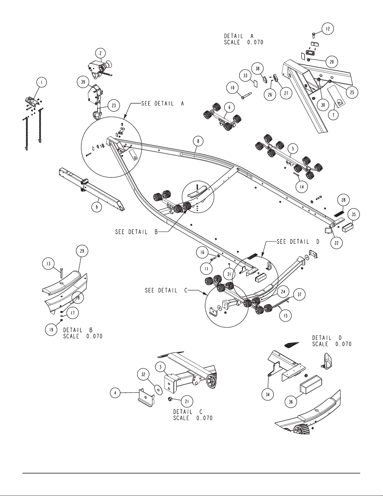
1
2
5
6
8
9
11
14
15
16
22
23
24
28
31
35
37
39
SEE DETAIL A
SEE DETAIL B
SEE DETAIL C
SEE DETAIL D
7
10
12
20
25
26
27
30
33
38
DETAIL A
SCALE 0.070
13
17
18
19
29
DETAIL B
SCALE 0.070
3
4
21
32
DETAIL C
SCALE 0.070
34
36
DETAIL D
SCALE 0.070
Diagram A
Midwest Industries, Inc. Ida Grove, IA 51445 800.859.3028 www.shorelandr.com 0003809
Page 2 06/05/07
Page 3
ITEM PART # DESCRIPTION QTY
NOTE
1 61395 COUPLER BAG WITH CHAINS 1
2 65659 PROFILE 2000 WINCH ASSY W/1802 PARTS 1
3 66835 REAR PIVOT WMENT (80 WIDE) 1
4 66836 REAR PIVOT STOP WMENT (2X5) 2
5 66839 ROLLERARM 8 ROLLER 2X4 2
6 66874 ROLLERARM 4 ROLLER 2X4 2
7 68271 TONGUE COVER PLATE 1
8 69286 FRAME WMENT 80 WIDE 181 LONG 1
9 69308 SWINGTONGUE ASSY 55IN NON BRAKE FG 1
10 0110114 HH 1/2-13 X 4 CS GR5 1
11 0120281 HH 3/4-16 X 4 CS GR5 2
12 0140094 HH 1/2-13 X 1 1/2 CS GR5 1
13 0210130 CARR 3/8-16 X 3 3/4 GR5 2
14 0210220 CARR 1/2-13 X 4 1/2 GR5 2
15 0810965 SCREW #10 X 1 1/2 SQ PAN SELF DRILL 2
16 1310120 WASHER USS FLAT 3/4 ULTRASEALED 2
17 1340030 LOCKWASHER 3/8 S/T MED ULTRASEAL 2
18 1340095 WASHER USS FLAT 3/8 2
19 1410109 HEX NUT 3/8-16 2
20 1440102 HEX LOCKNUT FLANGE 1/2-13 W/T&T 4
21 1440321 HEX LOCKNUT 3/4-16 GRB 2
22 2400026 TIE DOWN RETRACTABLE 2
23 3310050 800 LB SWIVEL JACK 1
24 3510022 GROMMET 7/16IN MOLDED 1
25 3510030 GROMMET 7/8IN MOLDED 8
26 3510158 PLASTIC DRIVE RIVOT 4
27 3510253 LIGHT BEZEL - AMBER 2
28 3510368 TAILLIGHT STEP PAD TREAD TAPE 2
29 3510542 MOLDED REAR CROSSMEMBER PAD 2
30 3510597 GROMMET 13/16IN WITH SPLIT 9/16ID 2
31 3520010 PLUG 13/16 IN BLACK PLASTIC 2
32 4811339 WASHER NYLON - 13/16 ID X 3-3/4 2
- 4811348 DECAL BLACK AND WHITE EQUILOAD 2
- 4850414 DECAL LUND LARGE CHROME 2
- 4850417 DECAL LUND CHROME WING LARGE LEFT 1
- 4850418 DECAL LUND CHROME WING LARGE RIGHT 1
33 5110127 REFLECTOR ANDERSON AMBER 2
34 5110348 BO LICENSE PLATE BRACKET 1
- 5110559 HARNESS TONGUE 4WIRE FULL GROUND 1
- 5110565 HARNESS FRAME 214" FULL GROUND RT 1
- 5110566 HARNESS FRAME 214" FULL GROUND LT 1
35 5110569 TAILLIGHT RIGHT LED PETERSON 1
36 5110570 TAILLIGHT LEFT LED PETERSON 1
37 5110571 LIGHT CLUSTER THREE LED 1
38 5110572 MARINE YELLOW CLEARANCE LIGHT 2
39 TA0991 WINCH STAND KIT 9" W/MTG HDWE 1
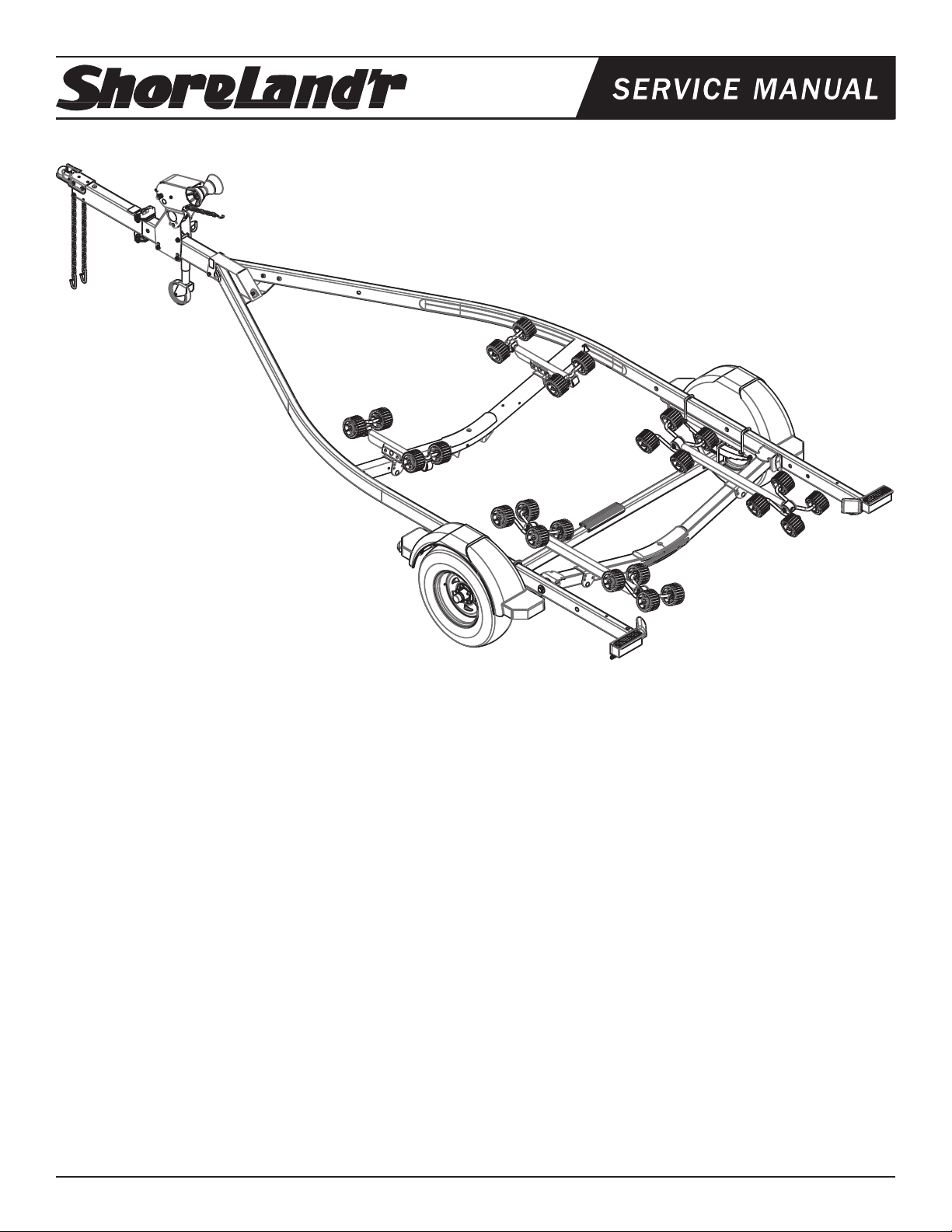
LUXR2314SW (All Colors) Specications:
Capacity: 2300 lbs.
GVWR: 2995 lbs.
GAWR: 2995 lbs.
Ship Wt: 575 lbs.
Frm Size: 2X4 (11 Ga)
Tire Size: ST215/75R14-C
Rim Size: 14 X 6 “J”
Brake: N/A
Coupler: 2”
Safety Chn: 7600 lb.
Suspension: 5 Leaf Hook Springs
Tongue Size: 3 X 5 X 65” Swing Tongue
FINAL ASSEMBLY INSTRUCTIONS
Remove the hardware bag from the frame, remove parts and sort
by size. Remove all the banded items from the frame.
ShoreLand’r offers their product line in either galvanized or paint-
ed nish. When ordering parts it is important that you specify the
nish or color you have on your product. The ve (5) digit number
along with a two (2) digit space _ _, note the parts which can be
purchased with various nishes. When ordering these items use
the ve (5) digit number along with a two (2) digit sufx for the
proper nish.
01.........White
03.........Black
14 ......... Blue
22 ......... Red
24 ......... Majestic Red
39 ......... Galvanized w/Silver Plastic Components
Midwest Industries, Inc. Ida Grove, IA 51445 800.859.3028 www.shorelandr.com 0003809
Page 3 06/05/07
TONGUE
Install the swing tongue by sliding it in the front of the tongue channel. Line the holes in the tongue with the holes in the tongue chan-
nel. Install the 1/2” x 4” hex bolt in the front cross hole and secure
with a 1/2” lock nut.
Remove the wire harness from the rear of the tongue. Place it
through the hole provided in the tongue cover plate.
Secure the tongue cover plate in position with the same 1/2” x 11/2” hex bolt that secures the back of the tongue to the tongue
channel of the frame. Secure with a 1/2” lock nut. Tighten both bolts
just installed.
Plug the tongue wire harness into the frame harnesses by match-
ing colors and ends. Push the extra wire provided either into the
rear of the tongue or else remove the grommets in the side frame
and place the extra wire in the side frame. Replace grommets just
removed.
SAFETY CHAINS
Locate a 3/8” x1 1/4” hex bolt. Slip the bolt through a 3/8” at washer, then place through the last link of one of the safety chains.
Place the bolt with chain attached through the hole provided in the
bottom front of the tongue. Secure with a 3/8” ange lock nut. Tighten. Repeat on the other side and safety chain.
RETRACTABLE TIE DOWNS
Locate the two retractable tie downs. Next locate one of the 7/16”
x 1 ½” ne threaded bolts supplied with the retractable tie down.
Insert it into the bottom hole on the retractable tie down so the bolt
is pointing through the back side of the tie down. Insert the bolt
through the hole provided in the taillight bracket just inside the side
frame. Secure with the 7/16” ange lock nut. Tighten.
Repeat the above process on the other tie down.
WINCH POST ASSEMBLY
Your trailer may have come with the jack already installed on the
winch base. However, in the event that it did not, use the following
instructions to attach the jack to the winch base before it is installed
on the tongue.
ASSEMBLY AND MOUNTING INSTRUCTIONS:
JACK ON A PROFILE 2000 WINCH BASE
The Prole 2000 winch base used on the 2” x 4” and 2” x 5” frame
trailers is formed so that the jack can be mounted directly to it elimi-
Page 4
ITEM PART # DESCRIPTION QTY
NOTE
1 0110037 HH 3/8-16 X 1 1/4 CS GR5 2
2 0110114 HH 1/2-13 X 4 CS GR5 1
3 0140090 HH 1/2-13 X 1 CS GR5 2
4 1340095 WASHER USS FLAT 3/8 4
5 1440101 HEX LOCKNUT FLANGE 3/8-16 W/T&T 2
6 1440102 HEX LOCKNUT FLANGE 1/2-13 W/T&T 3
7 2210300 CHAIN SAFETY 1/4(7MM)X 20LK W/LA 2
8 3310010 COUPLER #980 P2 ASSEMBLED 1
ITEM PART # DESCRIPTION QTY
NOTE
1 66365 SWINGTONGUE WMENT 37" REAR 1
2 66370 SWING TONGUE LATCH PIN 1
3 66850 FOLD-AWAY TONGUE WELDMENT (LONG) 1
4 0140096 HH 1/2-13 X 1 3/4 CS GR5 2
5 1340100 WASHER USS FLAT 1/2 4
6 1440102 HEX LOCKNUT FLANGE 1/2-13 W/T&T 2
7 1540305 HAIRPIN COTTER #9 ZP 1
8 3510030 GROMMET 7/8IN MOLDED 1
9 3510169 WIRE CLIP ADHESIVE BACK 1
- 4850182 DECAL SWINGTONGUE INSTRUCTION 1
- 4850183 DECAL SWINGTONGUE PINCH POINT 1
10 4850412 DECAL WARNING CAPACITY SWING TONGUE 1
1
2
3
4
5
6
7
8
1
2
3 4
5
6
7
8
9
10
Diagram B
Midwest Industries, Inc. Ida Grove, IA 51445 800.859.3028 www.shorelandr.com 0003809
Page 4 06/05/07
Page 5

ITEM PART # DESCRIPTION QTY
NOTE
1 60340 JACK INSIDE SPACER ZYU 1
2 60341 JACK RETAINER PLATE ZYU 1
3 60816 WINCH POST SPACER 1
4 60931 WINCH POST 9IN 1
5 65659 PROFILE 2000 WINCH ASSY W/1802 PARTS 1
6 0110118 HH 1/2-13 X 4 1/2 CS GR5 2
7 0210204 CARR 1/2-13 X 1 1/4 GR5 2
8 1440102 HEX LOCKNUT FLANGE 1/2-13 W/T&T 4
9 3110237 WINCH HANDLE DL1802 1
10 3310050 800 LB SWIVEL JACK 1
1
2
3
4
5
6
7
8
9
10
Diagram C
nating the need for other mounting hardware for attaching the jack
to the tongue. The jack required for mounting does not require the
mounting base or any of the original mounting hardware components.
Assemble as follows:
The jack must be mounted to the winch base before it is installed
WINCH POST INSTALLATION
The height that the bow eye is placed in your boat will determine
on the trailer tongue. If the winch base is already mounted on the
tongue, it will have to be removed for the jack installation.
Locate the hardware bag and sort all items by size.
Lay the Prole 2000 winch base on its side so the side that the jack
is going to be mounted on is up.
the length winch post required. Once this is determined, attach the
Place the inside jack spacer on the winch base so the center pro-
trusion ts down into the indent in the winch base.
Position the jack mounting plate so it is centered around the inside
jack spacer just positioned.
Lay the jack retainer plate on top of the jack mounting plate aligning
the holes in it with the holes in the winch base.
Insert the two ½” and 1 ¼” carriage bolts into the holes just aligned
in the jack retainer plate and the winch base. Secure in place with
½” lock washers and hex nuts. Tighten.
Once tightened, rotate the jack through its normal pivoting range to
make sure it is free to travel and is not binding up.
If jack pivots, place it on the tongue and secure in place with the
bolts and hardware provided with the trailer. Complete the assembly of the winch head to the winch base. Assembly is complete.
Midwest Industries, Inc. Ida Grove, IA 51445 800.859.3028 www.shorelandr.com 0003809
Page 5 06/05/07
winch base to the tongue with three 1/2” x 4” carriage bolts and
lock nuts.
Align the holes in the Prole 2000 mounting channel with the holes
in the top of the winch base. Attach the front of the winch head
mounting channel to the base by placing a 1/2” x 4-1/2” hex bolt
through the hole closest to the front of the winch base. Secure with
a lock nut. Do not tighten.
Note that the winch head can now be rotated either up or down.
Identify the correct hole combination to use to position the bow eye
roller just above the bow eye of your boat. When determined, secure in this position by placing the bushing as shown in Diagram C
inside the winch base so it aligns with the hole just identied for the
proper adjustment. Insert another 1/2” x 4-1/2” hex bolt through the
determined mounting hole in the mounting channel and winch base
making sure the bolt passes through the bushing as well. Secure
with a 1/2” lock nut. Tighten all bolts.
Page 6

ITEM PART # DESCRIPTION QTY
NOTE
1 65657 WINCH HOLDER CASE 1
2 68671 NYLON WINCH CASE BUSHING-3/4OD X 4.25 1
3 68683 CUP WASHER - WINCHES 2
4 0110064 HH 3/8-16 X 5 CS GR5 2
5 0110125 HH 1/2-13 X 5 1/2 CS GR5 1
6 204009 SHAFT BUSHING DL1400/2500 2
7 204360 SPACER WASHER DL1602 1
8 204808 REEL SPACER DL1700 1
9 204809 HANDLE HUT DL1602 1
10 205014 LOCK NUT DL1400/1700/1802/2500 1
11 205116 E-RING DL1602/1700/2500 1
12 205139 SPACER WASHER 1
13 205269 RATCHET PAWL BOLT 1/4-20 X 5 1
14 205270 LOCKNUT 3/8-16 JAM STYLE FOR WINCH 1
15 206281 EXTENSION SPRING - BLUE 1
- 206282 WARRANTY TAG DL1800/1802 WINCH 1
16 0210102 CARR 3/8-16 X 1 GR5 1
17 304731 DRIVE SHAFT UPPER DL1802 1
18 404868 REVERSABLE RATCHET PAWL 1
19 404872 RACHET SPACER DL1700/2500 1
20 404878 RATCHET SLEEVE DL1700/2500 1
21 1340095 WASHER USS FLAT 3/8 1
22 1440101 HEX LOCKNUT FLANGE 3/8-16 W/T&T 2
23 1440102 HEX LOCKNUT FLANGE 1/2-13 W/T&T 1
24 2210145 CHAIN 1/4(7MM)X 10 LINKS 1
25 3110348 WINCH REEL W/STRAP DL1800/1802 1
26 3510586 END CAP PROFILE 2000 TAN 2
27 3510587 ROLLER 4" BOW YATES TAN #450 1
28 3520011 PLUG 3/8IN WHITE PLASTIC 4
29 3520019 PLUG 1IN WHITE PLASTIC 2
- 4811349 DECAL PROFILE 2000 2
- 4811358 DECAL CLEAR W/BLACK LETTERS PROF 1
30 4811451 DECAL NMMA CERTIFIED TRAILER 1
- 4850383 DECAL CAPACITY DL1802A 1
1
2
3
4
5
6
7
8
9
10
11
12
13
14
15
16
17
18
19
20
21
22
23
24
25
26
27
28
29
30
Midwest Industries, Inc. Ida Grove, IA 51445 800.859.3028 www.shorelandr.com 0003809
Page 6 06/05/07
Page 7

ITEM PART # DESCRIPTION QTY
NOTE
1 4279 SHIM PAD U BOLT 12GA FRAME 4
2 66162 SPRING BRKT 10IN SINGLE 2
3 66473 AXLE ASSY80 WIDE 1
4 68610 SPRING BRKT BUSHING PLATED ZYU 2
5 68614 SPRING CLAMP 1/4X1 1/2X4 ZYU 2
6 68616 SPRING AND AXLE U-BOLT PLATE 2
7 69258 FENDER 10IN POLY RIGHT 1 HOLE 1
8 69259 FENDER 10IN POLY LEFT 1 HOLE 1
9 0110170 HH 9/16-18 X 3 1/4 CS GR5 4
10 0140040 HH 3/8-16 X 1 CS GR5 8
11 0310170 SUB 1/2 X 2 5/16 X 6 1/2 4
12 0310276 SUB 1/2 X 2 9/16 X 6 1/2 4
13 1310163 WASHER 1.377X.39X.105 8
14 1410229 HEX LUGNUT 1/2-20 13/16 OD Z&U 10
15 1440101 HEX LOCKNUT FLANGE 3/8-16 W/T&T 8
16 1440102 HEX LOCKNUT FLANGE 1/2-13 W/T&T 16
17 1440259 HEX LOCKNUT 9/16-18 GRA 4
18 3510022 GROMMET 7/16IN MOLDED 4
19 3510158 PLASTIC DRIVE RIVOT 4
20 3510253 LIGHT BEZEL - AMBER 2
21 3510263 RUBBER CUP WASHER 8
22 4610048 SPRING 5 LEAF HOOK 2
23 5110572 MARINE YELLOW CLEARANCE LIGHT 2
1
2
3
4
5
6
7
8
9
10
11
12
13
14
15
16
17
18
19
20
21
22
23
Diagram D
Tire Size and Carrying Capacity Chart
Tire Size .......................ST215/75R 14-C
GVWR ..........................2995 lb.
Carrying Capacity ......... 2300 lb.
Axle...............................Non-Brake
Refer to the tire side wall for correct tire pressure.
Recommended carrying capacity is based on shipping weight of
the trailer with standard equipment. Adding optional equipment
may decrease the trailer’s carrying capacity.
Midwest Industries, Inc. Ida Grove, IA 51445 800.859.3028 www.shorelandr.com 0003809
Page 7 06/05/07
Page 8

ITEM PART # DESCRIPTION QTY
NOTE
1 66155 AXLE WMENT (80 WIDE) 1
2 68673 2" PLASTIC CHANNEL BRACKET 1
3 0210130 CARR 3/8-16 X 3 3/4 GR5 1
4 1340206 WASHER 1.5 OD X .765 ID X .186/.206 2
5 1440101 HEX LOCKNUT FLANGE 3/8-16 W/T&T 1
6 1440349 HEX NUT SLOTTED PLAIN 2
7 1540038 COTTER KEY 1/8 X 1 1/2 ULTRASEAL 2
8 3510132 AXLE PAD 12IN BLK 1
9 4410089 SPINDLE SLEEVE 1 3/8-1 1/16 2
10 4410130 SEAL 1 3/8IN 2
11 4410246 SL BEARING PROTECTOR BRA 2
12 4410247 BEARING BUDDY - STAINLESS STEEL 2
13 4440160 ROLLER BEARING 1 1/16IN 2
14 4440170 ROLLER BEARING 1 3/8IN 2
15 4470400 HUB 1 3/8 X 1 1/16 CAST 2
1
2
3
4
5
6
7
8
9
10
11
12
13
14
15
Midwest Industries, Inc. Ida Grove, IA 51445 800.859.3028 www.shorelandr.com 0003809
Page 8 06/05/07
Page 9

ITEM PART # DESCRIPTION QTY
NOTE
1 62087 PLASTIC SPACER REAR PIVOT ARM 1
2 66873 ROLLERARM XR FRONT 1
3 66888 ROLLERARM MTG BRKT WMENT 1
4 68270 T BAR ROLLERPIN 2
5 68672 FLAT WASHER W/TONGUES FOR ROLLER 4
6 0210127 CARR 3/8-24 X 3 W/1 THRD GR8 4
7 0210220 CARR 1/2-13 X 4 1/2 GR5 1
8 0240210 CARR 1/2-13 X 3 GR5 1
9 1310121 WASHER SAE FLAT 4
10 1440100 HEX LOCKNUT 3/8-24 GRA 4
11 1440102 HEX LOCKNUT FLANGE 1/2-13 W/T&T 2
12 1540350 BULL RING PLAIN 4
13 3510259 SWIVEL BLOCK MOLDED PLASTIC 2
14 3510260 ROLLER WITH MOLDED HUB 5IN 4
15 3510261 ROLLER BUSHING MOLDED 4
1
2
3
4
5
6
7
8
9
10
11
12
13
14
15
Diagram E
XR SERIES
The XR-series rear roller rack is installed by placing the roller arm
assembly mounting channel over the rear cross member and se-
curing in place with a ½” x 4 ½” hex bolt and lock nut. (See Detail
E). Note that it should be left loose until the boat is placed on the
trailer. Repeat on the other roller arm assembly. Once the proper
location is determined, it may be tightened.
Midwest Industries, Inc. Ida Grove, IA 51445 800.859.3028 www.shorelandr.com 0003809
Page 9 06/05/07
Page 10

ITEM PART # DESCRIPTION QTY
NOTE
1 66837 ROLLERARM 2X4 EQUILOAD 1
2 68269 INLINE ROLLERPIN 19 1/2 4
3 68672 FLAT WASHER W/TONGUES FOR ROLLER 8
4 0210127 CARR 3/8-24 X 3 W/1 THRD GR8 4
5 1310121 WASHER SAE FLAT 8
6 1440100 HEX LOCKNUT 3/8-24 GRA 4
7 1540350 BULL RING PLAIN 8
8 3510259 SWIVEL BLOCK MOLDED PLASTIC 2
9 3510260 ROLLER WITH MOLDED HUB 5IN 8
10 3510261 ROLLER BUSHING MOLDED 8
1
2
3
4
5
6
7
8
9
10
Midwest Industries, Inc. Ida Grove, IA 51445 800.859.3028 www.shorelandr.com 0003809
Page 10 06/05/07
Page 11

SPRINGS
Position the axle so it is properly aligned with the trailer. Place the
springs on the top side of the spring pads welded to the axle. (See
chassis Diagram D). Note that the hook end of the spring must be
mounted to the rear of the trailer. Place a spring clamp on the top
center of the spring as shown. Next place the 1/2” x 6-1/2” U-bolts
down over the top of the spring clamp, spring and axle as shown.
Place the spring and axle U-bolt plate onto the ends of the two U-
bolts just placed. Secure in place with 1/2” lock nuts. Thread onto
the U-bolts but do not tighten securely until the complete unit is in
position on the trailer. Repeat on the other spring.
AXLE
Place one of the spring bracket bushings into the rear of the spring
bracket and secure with a 9/16” x 3 1/4” hex bolt and hex lock nut.
Repeat in other spring bracket.
Position the axle under the frame, then hook the hook loop of the
spring around the bushings just installed. Note that if the axle is
positioned too low when trying to hook, the hooks will not hook
around the bushings.
Raise the front of the springs up so they align with the front hole
of the spring bracket. Secure in place with 9/16” x 3-1/4” hex bolts
and lock nuts.
Tighten all axle U-bolts and spring bolts not tightened at this time.
TIRE & WHEEL ASSEMBLY
Mount the tire and wheel assemblies using the 1/2” lug nuts provided. Tighten to 85-95 ft./lb. of torque using the rotation pattern as
shown in the ShoreLandr ’s Owners Manual. Re-torque the lug
nuts after 50 miles of driving and then periodically thereafter.
TRAILER ADJUSTMENTS
The adjustment of the trailer to your boat is very important not only
for the trailer, but also the boat. Failure to do so may lead to potential failure or damage to either the trailer or boat. Adjust as follows:
AXLE ADJUSTMENT
The amount of tongue weight on your trailer can be adjusted as
follows:
achieved, move the roller rack system so that the rollers are just to
the outside of a strake. The rollers need to be adjusted so that you
have a minimum of one to two inches of clearance between the
keel of the boat and the center cross member pads. This will help
center the boat when loading and unloading.
When the desired position is determined, tighten only enough to
hold the rollers from moving while the other adjustments are being made. Final tightening will be done at the end of the adjusting
process.
FRONT SUPPORT SYSTEM
XR SERIES ROLLER
The front roller assemblies on the XR series will need to be adjusted
to t your boat. Place the roller assemblies so that the outside set
of rollers is just to the outside of a strake if your boat has strakes.
This is a desired location if the front of the boat isn’t setting to high
on the trailer with respect to the frame. Positioned as described will
help with centering your boat. If there are no strakes the roller assemblies can be positioned anywhere.
As a rule, when the XR roller arm assemblies are moved away from
the centerline of the trailer the front of the boat will be lowered with
respect to the trailer frame. The rollers should be moved outward
until the keel of the boat is within 1-2 inches of the front cross member pad. The boat should be kept as low as possible on the trailer
for better towing but must also be positioned so that the front of the
boat is either level or slightly higher in front that the rear. The boat
will unload easier if the front of the boat is slightly higher than the
rear.
WINCH POST
Once all other adjustments are complete the winch post can be adjusted. Slide the winch post base backward on the tongue until the
bow roller comes in contact with the boat. This bow roller needs to
be positioned directly above the boat bow eye to prevent your boat
from moving forward in the event of a sudden stop. It can be moved
up or down by removing the back bolt that mounts the winch head
to the base. When this bolt is removed, the head can be rotated up
or down to reach the desired height required to t your boat. Once
in this position, align the closest pair of holes in the brackets and
reinsert the bolt just removed. Tighten. Attach the winch strap and
crank the winch tight.
To lower the tongue weight, adjust the axle assembly forward. To
increase the tongue weight, adjust the axle backwards.
Attach the bow eye safety chain into the bow eye of the boat as
well. This is just another level of protection to keep your boat and
trailer together as one unit.
The distance that the axle assembly has to be moved will vary because it is directly related to the weight and center of gravity of the
boat placed on it.
Adjustments are now complete. Double check your boat for t. If
desired t has been achieved, tighten all fasteners that may have
either been left loose or have been loosened to do the adjusting.
Best towing is achieved when the tongue weight is 5-7% of the total
gross load of the complete unit.
NOTE:
All nuts and bolts must be tightened before towing.
Note: Wire harnesses will need care when moving the axle assembly.
Recheck all fasteners on the complete trailer to make sure they are
all tight and ready for towing. All fasteners should be periodically
REAR SUPPORT SYSTEM
check before towing.
Place the boat on the trailer so that the transom is located at the
rear of the support system. The center of the rear rollers on the
roller rack should be approximately 4” from the transom. This gives
See your ShoreLand’r Owner’s Guide for further technical infor-
mation regarding your trailer and its components.
you maximum support on the transom.
Refer to the tire side wall for correct tire pressure.
ROLLERS
Position the roller racks so they are far enough apart to give
your boat stability while transporting. When the desired width is
Midwest Industries, Inc. Ida Grove, IA 51445 800.859.3028 www.shorelandr.com 0003809
Page 11 06/05/07
Page 12

Midwest Industries, Inc. Ida Grove, IA 51445 800.859.3028 www.shorelandr.com 0003809
Page 12 06/05/07
 Loading...