

Page 1
®
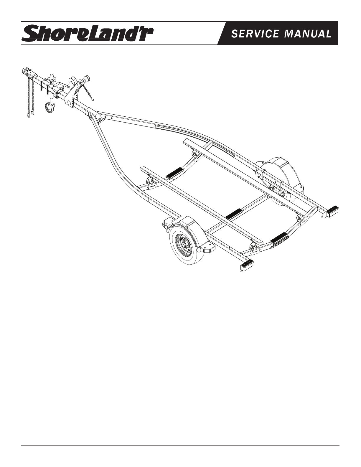
LUVE22LTSH
LUVE22LTSH Lund 2X3 Trailer
62340 Literature Packet - Trailers
80604_ _ Frame Bundle LUVE22L
61395 Coupler Bag w/Chains
3310050 Jack 800 lb. Swivel
3310053 Jack Mounting Hardware Bag
*ST185/80D13C Bias Tire / Dir Rim
*Check with your dealer/customer service representative for current tire/rim assembly part number.
ShoreLand’r offers its product line in painted nishes. When
ordering parts, it is important that you specify the nish or
color you have on your product. The 5-digit number along
with a 2-digit space _ _, note that the parts can be purchased
in various nishes.
03..........Black
39..........Galvanized w/Silver Plastic Components
Midwest Industries, Inc. Ida Grove, IA 51445 800.859.3028 www.shorelandr.com 0004036
REV A 01/05/2009
Page 1
Page 2
Midwest Industries, Inc. Ida Grove, IA 51445 800.859.3028 www.shorelandr.com 0004036
REV A 01/05/2009
Page 2
Page 3

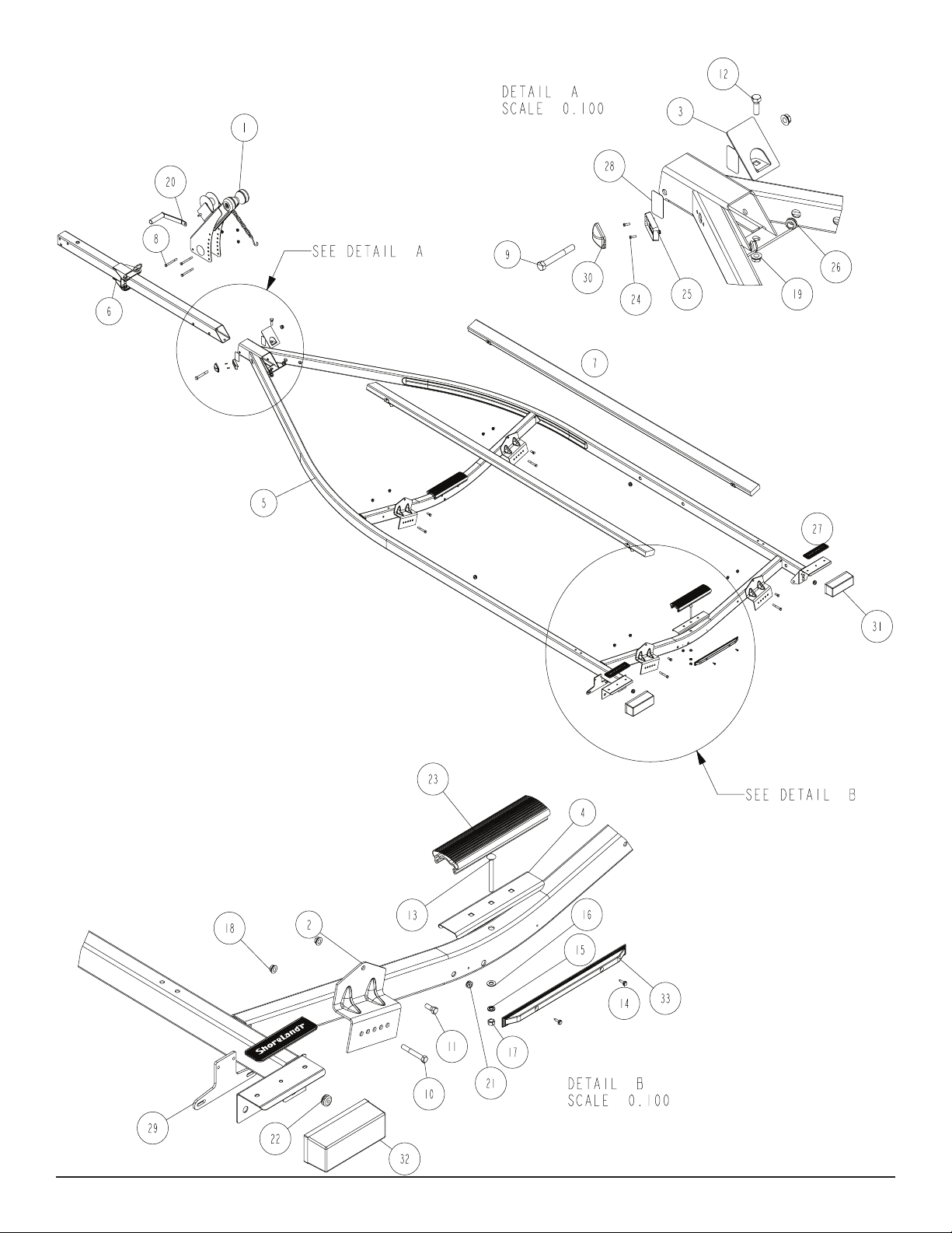
the wire harness through the hole in the tongue cover plate.
(See Detail A) Secure the tongue cover plate in position with a 1/2”
X 1-1/2” hex bolt and 1/2” lock nut. Tighten. Plug the tongue wire
harness ends into the frame harnesses by matching colors and ends.
Push the extra wire into the rear of the tongue or remove the grommets in the side frame and place the extra wire in the side frame.
Replace grommets just removed.
SAFETY CHAINS
Mount the safety chains to the front of the tongue by placing
a 3/8” at washer onto a 3/8” X 1-1/4” hex bolt, then insert the
bolt through the last link of the safety chain. Put the bolt through
the hole on one side of the tongue as shown. Place on another
at washer and secure with a 3/8” hex ange nut. Tighten. Repeat on the other chain on the other side of the tongue.
WINCH POST
Place the winch post assembly o n the tongue and secure
wi th thre e 3/ 8” X 4” h ex bolt s an d h ex flange lock n uts.
Place the nuts on the bolts but do not tighten because they
will have to be readjusted once the boat is on the trailer.
Remove the winch handle nut from the shaft. Align the hole in the
winch handle with the at surfaces on the shaft. Slide in position and
secure with the nut just removed. Tighten.
JACK
It is recommended that the jack be mounted on the right side of the
tongue. This will place it on the opposite side of the winch handle
to eliminate the possibility of the two interfering when being operated.
ASSEMBLY INSTRUCTIONS
Remove all items from the frame. Locate the hardware bag and sort
all items by size.
SWING TONGUE
The tongue comes shipped incorrectly in the frame. Slide the
tongue out from it’s shipping position and reinstall in the front
tongue channel. Line the holes in the tongue with the holes
in the tongue channel. Secure with a 1/2” X 4” hex bolt and
1/2” lock nut in the front cross hole.
Locate the coupler bag. Place the coupler on the end of the
tongue, align holes and secure with one 1/2” X 4” hex bolts and
hex ange lock nuts in the rear coupler hole. Place two 1/2” X
1” hex bolts into the front holes of the coupler and secure to the
each side of the tongue with 1/2” ange lock nuts. Tighten.
WIRE HARNESS
Locate the wire harness. Push the two triangular plugs in the hole
on the top of the tongue, then out the rear of the tongue. Place
Remove the hardware bag from the jack and sort all items by size.
Note that the jack mounting plate has only one pair of holes on one
side of the plate while the other side has holes punched to accommodate either 3”, 4”, or 5” tongue.
Place a 3/8” x 4” hex bolt into the single hole of the mounting plate
so the head of the bolt is on the jack side of the plate.
Once inserted, place one of the mounting channels onto the bolt so
the legs of the mounting channel are pointing away from the jack.
Place on a 3/8” at washer and hex nut. Thread on only far enough
to secure in place.
Repeat the above process on the other single hole of the mounting
plate.
Place the jack on the tongue so that the two bolts just installed are on
the top side of the tongue with the jack on the right side of the tongue
and the mounting channels on the other side of the tongue.
Visually check which of the bottom three holes in the plate will align
just under the bottom side of the tongue. Insert the remaining two 3/8”
x 4” hex bolts into these holes and then through the mating holes in
the mounting channel. Secure with 3/8” at washers and hex nuts.
Rotate the jack into the up position. Slide the jack forward or backward on the tongue to make sure it will not hit the frame of the trailer
when in the up position.
Tighten all of the mounting bolts to secure the jack assembly to the
tongue.
Always rotate the jack in the up position before towing the trailer.
Midwest Industries, Inc. Ida Grove, IA 51445 800.859.3028 www.shorelandr.com 0004036
REV A 01/05/2009
Page 3
Page 4

Midwest Industries, Inc. Ida Grove, IA 51445 800.859.3028 www.shorelandr.com 0004036
REV A 01/05/2009
Page 4
Page 5

V-BUNK ASSEMBLY (V-SERIES)
Position the bunks so that they are above the bunk brackets attached to the front and rear cross members. (See Detail B) Secure
the brackets on the bunk to the upright brackets with 3/8” X 1” hex
bolts and hex lock nuts. Tighten but do not over tighten because the
bunks must be able to rotate to conform to the boat bottom.
Midwest Industries, Inc. Ida Grove, IA 51445 800.859.3028 www.shorelandr.com 0004036
REV A 01/05/2009
Page 5
Page 6

Midwest Industries, Inc. Ida Grove, IA 51445 800.859.3028 www.shorelandr.com 0004036
REV A 01/05/2009
Page 6
Page 7

SPRINGS
Positions the axle so that it is aligned with the trailer.
Place the springs on the top side of the spring pads welded to the axle.
(See chassis diagram on page 4.) The hook end of the spring must be
mounted to the rear of the trailer. Place a spring clamp on the top center
of the spring. Place the 1/2” X 6-1/2” U-bolts over the top of the spring
clamp, spring and axle. Place the spring and axle U-bolt plate onto the
ends of the two U-bolts. Secure in place with 1/2” lock nuts. Tighten.
AXLE
Place a spring bracket bushing (Ref.#9, Detail E) into the rear of the
spring bracket and secure with a 9/16” x 3-1/4” hex bolt and hex lock nut.
Repeat in the other spring bracket. Position the axle under the frame,
hook the hook loop of the spring around the bushings just installed.
Note: If the axle is positioned too low, the hooks will not hook around the
bushings.
Raise the front of the springs up so they align with the front hole of
the spring bracket. Secure in place with 9/16” X 3-1/4” hex bolts and
lock nuts. Tighten all axle U-bolts and spring bolts.
TIRE & WHEEL ASSEMBLY
Mount the tire and wheel assemblies using the 1/2” ne threaded tapered lug nuts provided. Tighten to 85-95 ft./lb. of torque using the rotation pattern as shown in the ShoreLandr’s Owners Manual.
Re-torque the lug nuts a ft er 50 miles of driving and then
periodically thereafter.
Midwest Industries, Inc. Ida Grove, IA 51445 800.859.3028 www.shorelandr.com 0004036
REV A 01/05/2009
Page 7
Page 8

Midwest Industries, Inc. Ida Grove, IA 51445 800.859.3028 www.shorelandr.com 0004036
REV A 01/05/2009
Page 8
Page 9

TRAILER ADJUSTMENTS
Axle Adjustment
The amount of tongue weight on your trailer can be adjusted as
follows: To lower the tongue weight, adjust the axle assembly
forward. To increase the tongue weight, adjust the axle assembly
backward. The distance that the axle assembly has to be moved will
vary because it is directly related to the weight and center of gravity
of the boat placed on it. Best towing is achieved when the tongue
weight is 5-7% of the total gross load of the complete unit.
NOTE: The wire harness will need care when moving the
assembly.
Rear Support System
Place the boat on the trailer so that the transom is located
at the en d of t he bun k. Th e center of the re ar rolle rs on
the roller rack should be approximately 4” from the transom. This gives you maximum support on the transom.
The bunks must be positioned far enough apart to give your boat
as much stability as possible while transporting. Position the bunks
so they are located just to the outside of the boat’s strake. This will
help center your boat and assist when loading.
FRONT SUPPORT SYSTEM
Bunk
The front bunks should be adjusted either in or out so that the bunk
will continue to run just to the outside of the strake of the boat. Adjust
the bunks up so that there is approximately 1” clearance between
the keel of the boat and the center cross member pad.
Winch Post Adjustment
Slide the winch post assembly back towards the boat. The bow stop
roller needs to be located directly above the boat bow eye to prevent
your boat from moving froward in the event of a sudden stop.
Note t h at the o u ter w i n ch bas e h as sev e ral ho l e s of
adjustment. Changing the bolt location will change the angle of the
winch post and will raise or lower the height of the bow roller. Choose
the bolt location which best matches it to the bow eye height.
Th e in ner and oute r wi nch post ch ann els can te les cope
either i n or o ut with r es pe ct to each o th er to lengthen o r
shorten the overall length of the post. Loosen the two bolts
located on the back, inside of the channels. Attach the winch
strap into the bow e ye and crank the w inch s tr ap in u nt il
the bow eye is located in it’s proper position just above the
bow eye. Slide the inner post in or out to a desired length.
Once the bow stop roller is located in it’s proper position above the bow
eye, tighten the bolts that secure the assembly to the tongue.
Attach the bow eye safety chain into the bow eye as well.
This is another level of protectio n to keep your trailer and
bo at to gethe r a s on e u nit . I t m ay be used to keep yo ur
boat on the trailer while loading and unloading at the ramp,
especially with a roller trailer.
Adjustments are now complete. Double check your boat
for t. If desired t has been achieved, tighten all fasteners that may have either been left loose or have been
loosened to do the adjusting.
See your ShoreLand’r Owner ’s Guide f o r further
tec hni c al info rma t ion reg ard ing you r tr a ile r an d it s
components.
Midwest Industries, Inc. Ida Grove, IA 51445 800.859.3028 www.shorelandr.com 0004036
REV A 01/05/2009
Page 9
Page 10

Midwest Industries, Inc. Ida Grove, IA 51445 800.859.3028 www.shorelandr.com 0004036
REV A 01/05/2009
Page 10
 Loading...