

Page 1
LUR15A
LUR15A-03 LUND TRAILER 1 1/2X3 R15
3310050 Jack 1000 LB Swivel
3310053 Jack Mounting Hardware Bag
* 5.30X12C Tire/TS Mod Rim
62340 Lit Packet Trailers
6917503 Keel Cradle Bundle 1X3/2X3 Roller
6943503 Hardware Box Roller R15
8054703 Frame Bundle LUR15
*Check with your dealer/customer service representative for current tire/rim
assembly part number.
LUR15A-39 LUND TRAILER 1 1/2X3 R15
3310050 Jack 1000 LB Swivel
3310053 Jack Mounting Hardware Bag
* 5.30X12C Tire/TS Mod Rim
62340 Lit Packet Trailers
6917500 Keel Cradle Bundle 1X3/2X3 Roller
6943500 Hardware Box Roller R15
8054739 Frame Bundle LUR15
*Check with your dealer/customer service representative for current
tire/rim assembly part number.
Midwest Industries, Inc. Ida Grove, IA 51445 800-859-3028 www.shorelandr.com 0004067
Page 1 of 7 3/05/2009
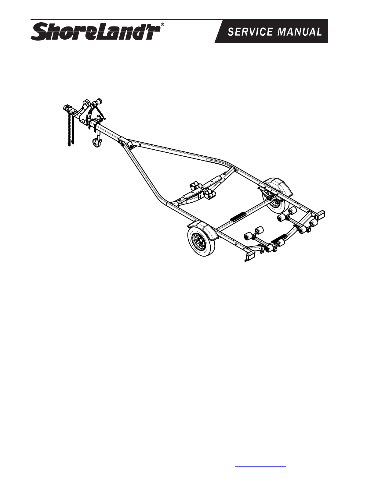
Shoreland’r
When ordering parts, it is important that you specify
the finish or color you have on your product. The 5digit number along with a 2-digit space _ _, note that
the parts can be purchased in various finishes.
03......... Black
39......... Galvanized w/Black Plastic Components
offers its product line in painted finishes.
Page 2
Midwest Industries, Inc. Ida Grove, IA 51445 800-859-3028 www.shorelandr.com 0004067
Page 2 of 7 3/05/2009
Page 3
Midwest Industries, Inc. Ida Grove, IA 51445 800-859-3028 www.shorelandr.com 0004067
Page 3 of 7 3/05/2009
Page 4

Midwest Industries, Inc. Ida Grove, IA 51445 800-859-3028 www.shorelandr.com 0004067
Page 4 of 7 3/05/2009
Page 5

Midwest Industries, Inc. Ida Grove, IA 51445 800-859-3028 www.shorelandr.com 0004067
Page 5 of 7 3/05/2009
Page 6
Midwest Industries, Inc. Ida Grove, IA 51445 800-859-3028 www.shorelandr.com 0004067
Page 6 of 7 3/05/2009
Page 7

Final Assembly Instructions
A
Remove the small parts from the frame by cutting the
bands. Remove the bolt bag and sort all nuts and bo lts by
size.
Tongue:
Remove the tongue assembly from the frame bundle and
install into the tongue channel and secure with a 1/2” 4” hex
bolt in the side of the tongue and tongue chan nel. Secure
with a 1/2” flange lock nut.
Place the tongue cover over the rear of the tongue channel
and secure with a 1/2” flat washer and 1/2” hex nut.
Tongue Wires:
Install the tongue wire harness through the top forward wire
hole and exit the rear of the tongue channel on the frame.
Install grommets and plug the tongue wire into the frame
harness by color.
Safety Chain:
Insert a 3/8” X 1-1/4” hex bolt with a 3/8” flat washer and
safety chain through the lower hole on the front of the
tongue. Secure with a 3/8” flat washer and 3/8” flange lock
nut. Repeat the procedure on the opposite side of the
tongue.
Coupler:
Mount the coupler onto the tongue with one (1) 1/2” X 4”
hex bolt into the rear of the coupler and tongue and using
two (2) 1/2” X 1” hex bolts into the two (2) front holes on the
coupler and tongue. Secure with 1/2” flange lock nuts.
Winch:
Secure the winch post to the tongue with three (3) 3/8” X 4”
hex bolts and 3/8” flange lock nuts. Mount the winch handle
to the winch using the special nut provided. Tighten with
winch post in a location that best fits your water craft.
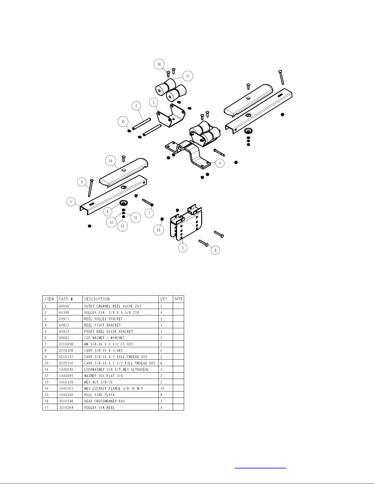
Keel Roller Assembly:
Open box and remove all parts and hardware bag. Open
hardware bag and sort parts.
Place 64923_ _ front keel guide bracket over front cross
member and align holes in bracket with those in the front
cross and insert 3/8” X 3” carriage bolts from rear to front
and secure 3/8” flange lock nuts. Place cradle assembly
with pin in center in the rear slot on top of the previously
attached bracket with bent ends facing forward. Take outer
channel assemblies and place on top of bracket aligning
holes and insert 3/8” X 3” hex bolts, secure with 3/8” flange
lock nuts. In the slots in the ends of the channel, insert 3/8”
X 5” carriage bolts through cross member and secure 3/8”
flange lock nuts.
xle and Wheel Assembly
Locate the axle for the trailer. Note that there is not a right or
left to the axle assembly. Place one of the springs on top of the
spring pad welded to the axle as shown in Diagram D. Drop two
(2) 3/8” x 2-3/16” x 2” U-bolts over the springs and down
through the holes in the spring pad. Secure with 3/8” flange lock
nuts. Repeat this process on the other spring mounting it so
that it is oriented on the axle the same as the first spring.
Slip a spring bushing spacer into the rear of the spring bracket,
align the bushing with the hole in the bracket and secure in
position using a 1/2” x 3” hex bolt and 1/2” flange lock nut.
Tighten. Repeat on the other spring bracket.
Slide the axle assembly under the trailer frame, raise up and
slide the rear of the springs above the bushings just installed.
Rotate the assembly up until the front spring eyes align with the
front holes in the spring bracket. Insert a 9/16” x 3-1/4” hex bolt
and secure with a 9/16” lock nut. Tighten. Tighten the U-bolt
attaching the springs to the axles at this time and any other
bolts that may have been left loose for ease of assembly.
Place the tire and wheel assemblies on the hubs and secure
with the 1/2” tapered lock nuts.
Tire and Wheel Assemblies
Mount the tire and wheel assemblies using the 1/2” fine
threaded tapered lug nuts provided. Tighten to 80-90 ft/lb. of
torque using the rotation pattern as shown in the Shoreland’r
Owners Manual. Re-torque the lug nuts after 50 miles of driving
and then periodically thereafter.
Adjustments:
Winch:
Once the boat is positioned on the trailer, adjust the winch post
to the boat; adjust the winch post to the boat. Adjust the bow
stop bracket so that the rubber bow stop is just above the bow
eye.
V-Bunk Assembly:
Place your boat on the trailer. Determine the spacing on the
roller rack. It may be necessary to adjust your roller rack either
further in or out from the position you have it assemblies. The
boat must be adjusted to miss any keel or strake which might
be on your particular boat.
IMPORTANT:
as possible for stability. This in most cases will allow your boat
to be as low as possible on the trailer for better trailering,
loading and unloading.
Once the roller racks have been spaced properly for your boat,
position the boat on the trailer with the transom
rear roller rack.
The roller racks should be spaced as far apart
with the
flush
Midwest Industries, Inc. Ida Grove, IA 51445 800-859-3028 www.shorelandr.com 0004067
Page 7 of 7 3/05/2009
 Loading...