

Page 1
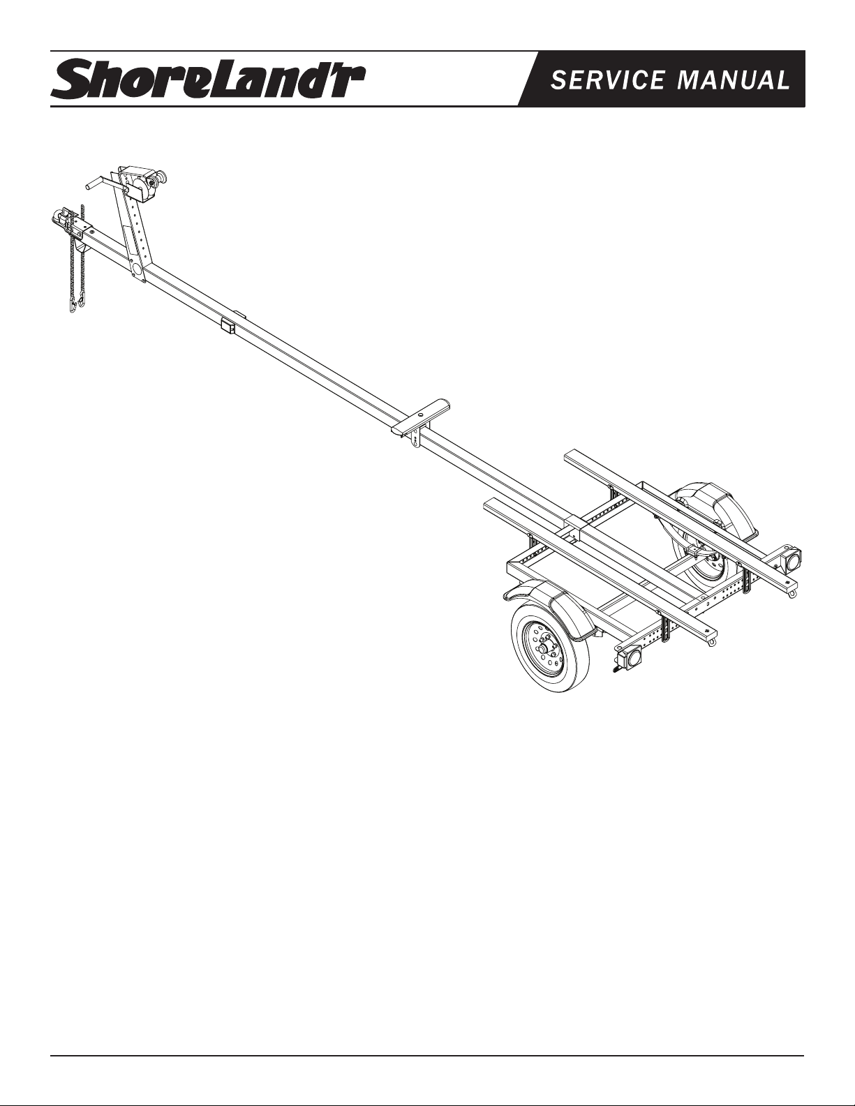
®
BUNDLES REQUIRED
LUB7TL-03 Lund Trailer Fishing - Tadpul
62340 Literature Bag - Trailers
4850413 Decal - Lund Small
6728003 Frame Bundle - Tadpul
*4.80 X 12B Tire/Mod Rim
6442803 Tongue Assy 3X3X17
3310050 Jack 800 lb. Swivel
3310053 Jack Mounting Hardware Bag
LUB7TL
LUB7TL-39 Lund Trailer Fishing - Tadpul
62340 Literature Bag - Trailers
4850413 Decal - Lund Small
6728039 Frame Bundle - Tadpul
*4.80 X 12B Tire/Mod Rim
6442800 Tongue Assy 3X3X17
3310050 Jack 800 lb. Swivel
3310053 Jack Mounting Hardware Bag
*Check with your dealer/customer service representative for current tire/rim assembly part number.
ShoreLand’r offers their product line in either galvanized or painted
nish. When ordering parts it is important that you specify the nish
or color you have on your product. The ve (5) digit number along
with a two (2) digit space _ _, note the parts which can be purchased
with various nishes. When ordering these items use the ve (5) digit
number along with a two (2) digit sufx for the proper nish.
03..........Black
39..........Galvanized W/Silver Plastic Components
Midwest Industries, Inc. Ida Grove, IA 51445 800.859.3028 www.shorelandr.com 0003662
REV B 01/23/2009
Page 1
Tire Size & Carrying Capacity Chart
Tire Size: 4.80 X 12
Load Range: B
Carrying Capacity: 780 lbs. per/tire
Refer to tire side wall for correct tire pressure.
Tongue Weight Adjustment
Approximate Tongue Weights for Best Towing. Slide the water
vehicle either forward or backward on the trailer until the proper
tongue weight has been achieved. The tongue weight should be 5%
to 7% of the total gross weight of the trailer and boat combined.
Page 2
Midwest Industries, Inc. Ida Grove, IA 51445 800.859.3028 www.shorelandr.com 0003662
REV B 01/23/2009
Page 2
Page 3
Final Assembly Instructions
Remove the small parts from the frame by cutting the banding. Remove the bolt bag and sort all the nuts and bolts by size.
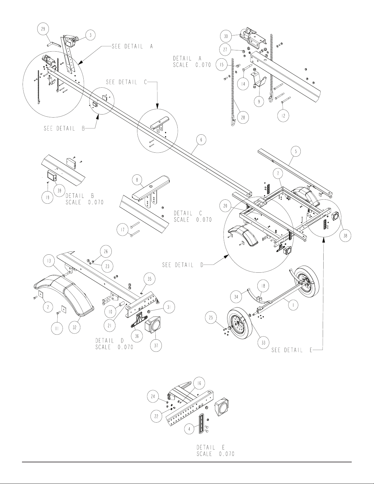
See Detail A
Side Marker Lights
Once the proper tongue is identied place it on the stands so it can
be prepared for installation into the frame. Locate the two amber
side marker lights shipped in the hardware box. Uncoil the wire and
insert the plug end into the larger, center hole that is drilled in the
side of the tongue. As the wire is inserted into the hole direct the wire
so that it will go to the forward end of the tongue. Pull the wire out
the front of the tongue. It will be connected to the tongue har¬ness
at a later time. Attach the light to the tongue using two (2) No. 10 x
3/4” self-tapping screws provided. Repeat this process on the other
light on the other side of the tongue.
Locate the tongue wire harness. Insert the end of the harness with
the small plug into the hole located in the top of the tongue. As the
wire harness is inserted note that there are two single bullet wires
towards the front plug of the tongue wire harness. Pull these wires
forward as the wire harness is inserted into the tongue. Plug the
single wires from the side marker lights installed earlier into the two
single bullets of the tongue harness. Pull the wire backward through
the tongue until the end comes out the rear of the tongue. Push the
additional back into the front of the tongue to keep it from damage
during use. Place a rubber grommet around the wire har¬ness and
in the hole in the top of the tongue to protect the wires from damage during use.
Route the harness plug at the rear of the tongue through the hole
provided in the side of the tongue. Pull both the plug and the white
Midwest Industries, Inc. Ida Grove, IA 51445 800.859.3028 www.shorelandr.com 0003662
REV B 01/23/2009
Page 3
Page 4

ground wire out the hole. They will be attached later once the tongue
is installed in the frame.
Place a 1/2” ange lock nut on the bolt inside the tongue. Repeat this
process on the other side of the tongue. Once the bolts are installed,
tighten all nuts left loose at this time.
Locate the bolt on tongue stand Item No. 10 in Detail A. Look at the
bottom side of the tongue and locate the slotted key slot hole in the
tongue. Note that one end of the tongue stand has a dart or arrow
shaped end. With the tongue stand positioned 90 degrees to the
centerline of the tongue, insert the dart or arrow end of the tongue
stand into the key slotted hole. Once it is inserted, turn the tongue
stand 90 degrees so that it now is in line with the centerline of the
tongue. Attach the front end of the tongue stand to the tongue using
Insert the tongue assembly through the front channel of the frame
far enough so the rear of the tongue is inserted into the rear cross
member. Align the cross hole in the front channel and the tongue
and insert a 3/8” x 4” hex bolt. Secure with a 3/8” ange lock nut.
Place a second 3/8” x 4” hex bolt down through the hole in the rear
of the tongue and the rear cross member. Place on a 3/8” ange
lock nut. Tighten.
a 1/2” x1” hex bolt and ange lock nut. Tighten.
Connect the tongue wire harness into the side frame harness of
Safety Chains
Locate the safety chains. Place a 3/8” at washer on a 3/8” x 1-1/4”
hex bolt. Insert the bolt through the last link in the safety chain and
then into the lower hole provided in the front of the tongue. Secure
with a 3/8” ange lock nut. Tighten. Repeat on the other chain.
Coupler
Place the coupler on the top of the tongue. Align the holes in the
the trailer by matching plugs. Attach the white ground wire of the
tongue harness to the frame using a No. 10 x 3/4” self-tapping screw
provided so that a good ground connection is made between the
frame of the trailer and the tow vehicle. Push all extra wires used to
make the connection back inside either the side frames of the trailer
or else into the tongue. Place a second rubber grommet into the
hole where the wires exit the tongue to protect them from damage
during normal use.
coupler with the holes in the tongue. Place a 1/2” x 4” hex bolt through
the back holes of the coupler and the tongue. Secure with a 1/2”
ange lock nut but do not tighten at this point.
Jack
t is recommended that the jack be mounted on the right side of the
tongue. This will place it on the opposite side of the winch handle
Place a 1/2” x 1” hex bolt through the front hole on one side of the
coupler and the tongue so that the head of the bolt is to the outside.
to eliminate the possibility of the two interfering when being operated.
Midwest Industries, Inc. Ida Grove, IA 51445 800.859.3028 www.shorelandr.com 0003662
REV B 01/23/2009
Page 4
Page 5

Midwest Industries, Inc. Ida Grove, IA 51445 800.859.3028 www.shorelandr.com 0003662
REV B 01/23/2009
Page 5
Page 6

Midwest Industries, Inc. Ida Grove, IA 51445 800.859.3028 www.shorelandr.com 0003662
REV B 01/23/2009
Page 6
Page 7

Remove the hardware bag from the jack and sort all items by size.
Lay the mounting plate at so the area that the jack will be mounted
is raised above the outside edges. Locate the cloverleaf shaped
washer. Place it on the mounting plate so the center pointed area
mates with the indent in the mounting plate. Rotate the cloverleaf
shaped washer so that the notches in it match the holes in the
mounting plate.
Place the jack assembly on the mounting plate by centering the
mounting hole with the cloverleaf plate just placed in position.
Insert two of the 3/8” x 1” carriage bolts in the holes of the swivel
bracket washer. Place the washer onto the jack assembly so the bolts
go through the mounting hole of the jack assembly and through the
notches in the cloverleaf shaped washer. Insert the bolts completely
down through the mounting plate. Secure in place with 3/8” ange
lock washers. Tighten.
3/8” ange lock nuts.
Axle:
Position the axle with springs under the frame. Place the spring
bushing spacer into the rear frame brackets. Align with the top hole
and secure into the bracket from the outside in with a 1/2” X 3” hex
bolt hex bolt and 1/2” ange lock nut. Tighten
Install a 1/2” X 3” hex bolt into the bottom hole in the rear bracket.
Tighten, but do not over tighten. Insert the slipper end of the spring
between the two (2) bolts installed into the back bracket. Secure
the eye of the spring into the bottom hole of the front bracket with a
1/2” X 3” hex bolt and 1/2” ange lock nut. Tighten.
Tighten all bolts and nuts, but do not over tighten.
Remove the 1/2” lug nuts from the hardware bag. Mount the tire
and rim assemblies with 1/2” lug nuts using 85-95 ft./lbs. of torque
using a proper tightening procedure.
Note that the jack mounting plate has only one pair of holes on one
side of the plate while the other side has holes punched to accom-
modate either 3”, 4”, or 5” tongue.
Place a 3/8” x 4” hex bolt into the single hole of the mounting plate
so the head of the bolt is on the jack side of the plate.
Once inserted, place one of the mounting channels onto the bolt so
the legs of the mounting channel are pointing away from the jack.
Place on a 3/8”lock washer and hex nut. Thread on only far enough
to secure in place.
Repeat the above process on the other single hole of the mounting
plate.
Place the jack on the tongue so that the two bolts just installed are on
the top side of the tongue with the jack on the right side of the tongue
and the mounting channels on the other side of the tongue.
Visually check which of the bottom three holes in the plate will align
just under the bottom side of the tongue. Insert the remaining two
3/8” x 4” hex bolts into these holes and then through the mating
holes in the mounting channel. Secure with 3/8” lock washers and
hex nuts.
Rotate the jack into the up position. Slide the jack forward or backward on the tongue to make sure it will not hit the frame of the trailer
when in the up position.
Tighten all of the mounting bolts to secure the jack assembly to the
tongue.
Assembly should be complete except for tightening some of the
bolts. These bolts were left loose to aid in adjusting the trailer to the
boat only. All bolts and must be tightened before towing.
NOTE: The law requires that the white ground wire on both the
tongue wire harness and vehicle harness be properly grounded to
the respective trailer and vehicle frames.
Adjustments:
Bunk Adjustments:
Place your boat on the trailer.
Determine the spacing on the bunks. It may be necessary to adjust
your bunks either in or out from the position preset at the factory.
The bunks must be adjusted to miss any keel or strake which might
be on your particular watercraft.
IMPORTANT: The bunks should be spaced as far apart as possible for stability. This in most cases will also allow your water craft
to be as low as possible on the trailer for better trailering, loading
and unloading.
NOTE: The rear tie-down straps are not provided with the trailer.
NOTE: Check all fasteners and tighten before towing.
See your ShoreLand’r Owner’s Guide for further technical information.
Always rotate the jack in the up position before towing the trailer.
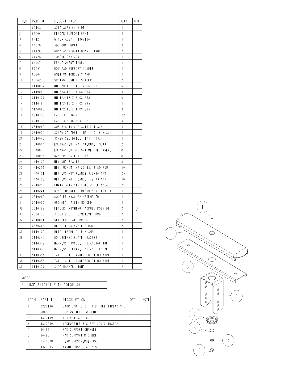
Bunk:
Position two (2) long 2X4 bunks on the frame. Fasten in a desired
location that best ts your watercraft using 3/8” carrigae bolts, 3/8”
lock washer and 3/8” hex nuts. Refer to parts drawing for place-
ment. NOTE: Bunk brackets with the embossed side faces the to
the frame.
Springs:
Fasten the springs to the axle with 3/8” axle u-bolts and secure with
Midwest Industries, Inc. Ida Grove, IA 51445 800.859.3028 www.shorelandr.com 0003662
REV B 01/23/2009
Page 7
Page 8

Midwest Industries, Inc. Ida Grove, IA 51445 800.859.3028 www.shorelandr.com 0003662
REV B 01/23/2009
Page 8
 Loading...