

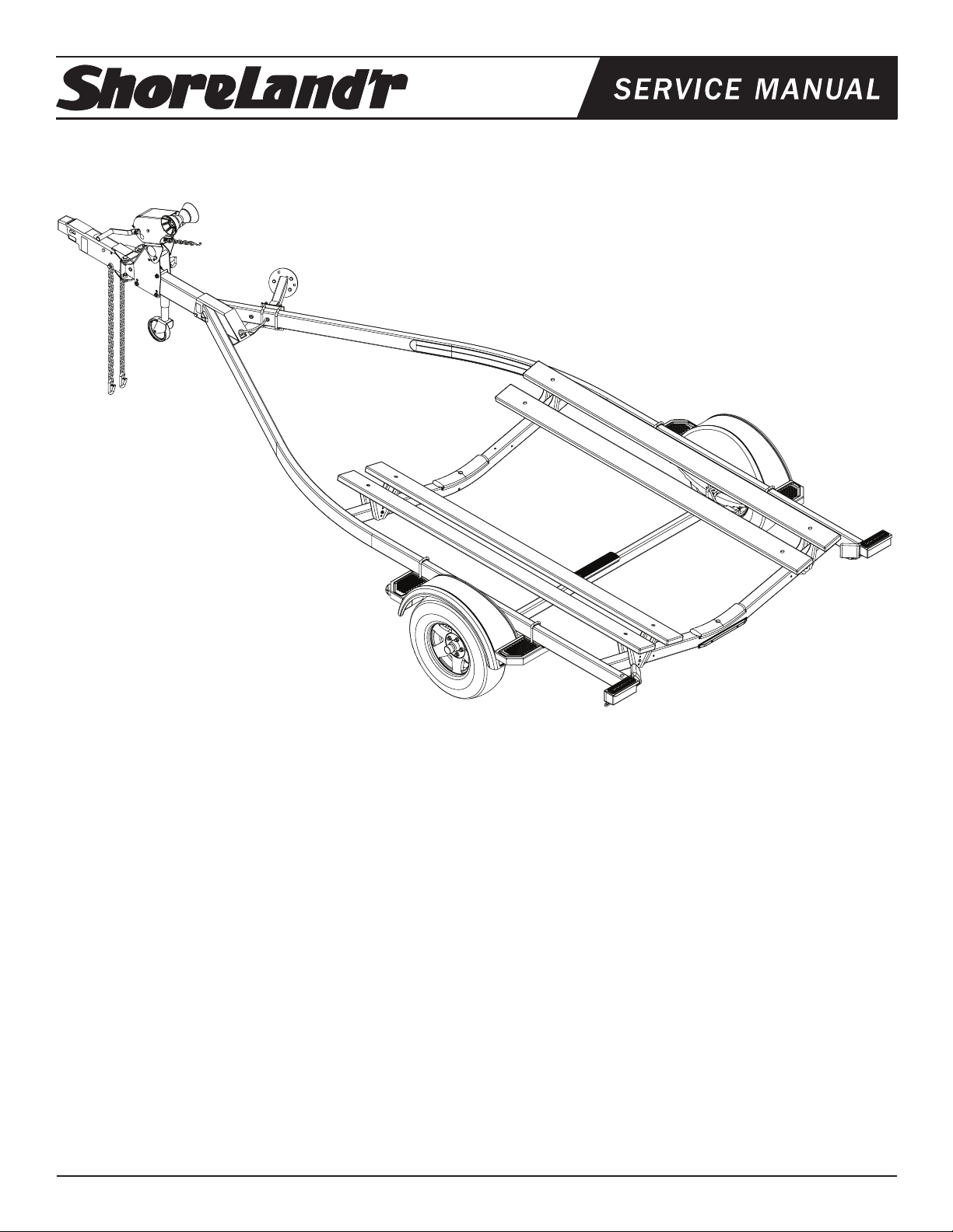
®
LUB29CBSW
LUB29CBSW 2X4 Lund Trailer
LUB29CBSW Specications
69082 Literature Bag - Trailers (Brakes)
80532-_ _ Frame Bundle - LUB29CBSW
TA0028-_ _ Spare Tire Kit (2X4 & 2X5 Frm)
*
ST215/75R14C OWL Alum Star Rim
LU0106-_ _ Loadguide - 2X4 Frame (4-Hole)
Capacity 2900 lbs.
GVWR: 3740 lbs.
GAWR: 3740 lbs.
Ship Wt: 725 lbs.
Frm Size: 2X4 (11 Ga)
*Check with your dealer/customer service representative for current tire/rim assembly part number.
Tire Size: ST215X75R14-C
Rim Size: 14 X 6 “J”
Brake: Surge Hydraulic
ShoreLand’r offers its product line painted nishes. When ordering
parts, it is important that you specify the nish or color you have on
your product. The 5-digit number along with a 2-digit space _ _, note
the parts which can be purchased with various nishes.
01........ White
03........ Black
14........ Blue
22........ Red
24........ Majestic Red
Coupler: 2” Actuator, 7000 lbs.
Suspension: 5 Leaf Hook Springs
Tongue Size: 3X5X55” Swing Tongue
Table of Contents
Frame Drawing & Bill of Materials ...............................2-3
Swing Tongue, Actuator, Safety Chain (Disc) .............. 4
Prole 2000 Winch / Post Drawing & BOM ................5-6
Axle Assembly Dwg / BOM (Disc) ...............................7-8
Tire Size & Carrying Capapcity Chart.......................... 8
More Information .........................................................9
Bunk Assembly ............................................................ 10
Load Guides ............................................................. 11
Spare Tire Bracket .......................................................12
Trailer Adjustments ......................................................13
Midwest Industries, Inc. Ida Grove, IA 51445 800.859.3028 www.shorelandr.com 00036853
REV B 02/06/2009
Page 1
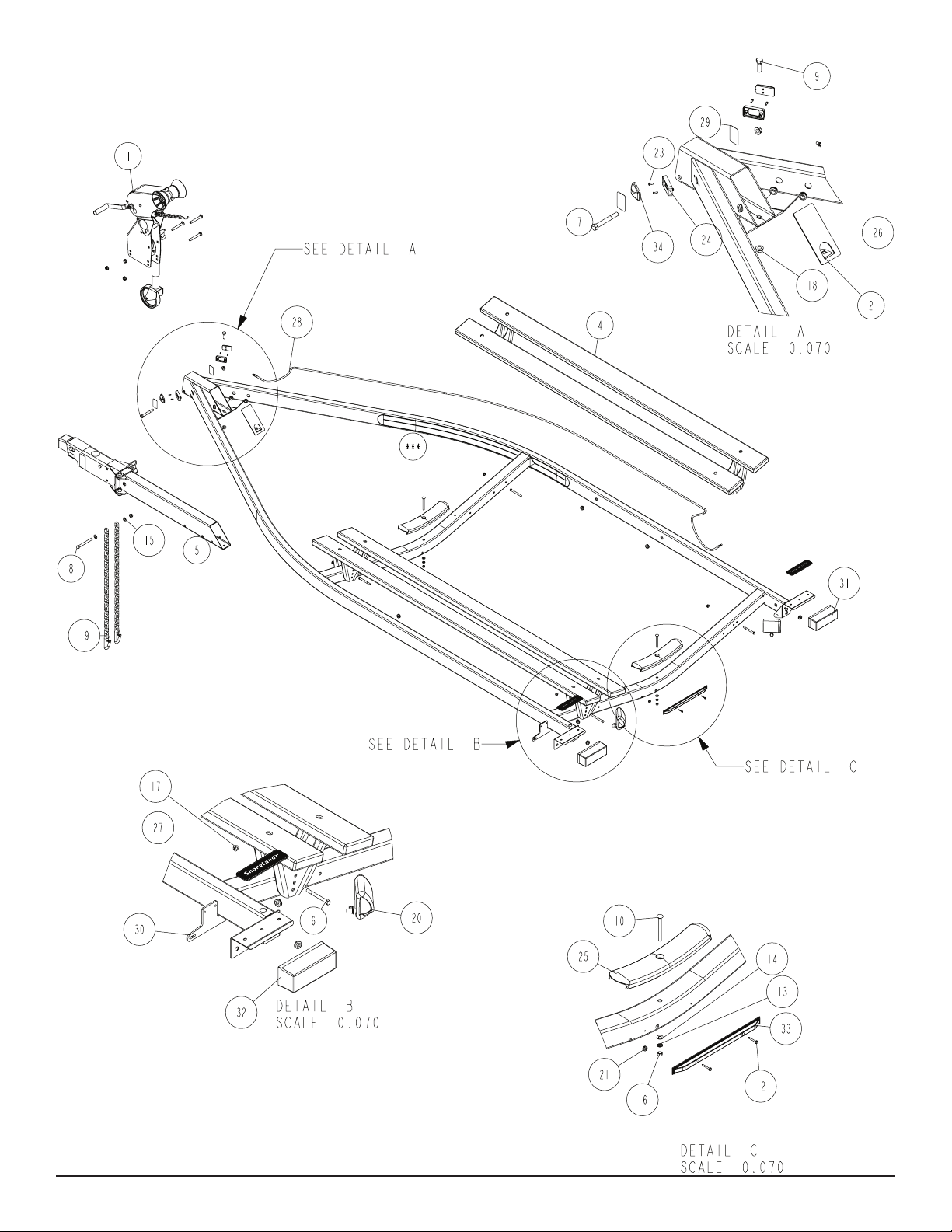
Diagram A
Midwest Industries, Inc. Ida Grove, IA 51445 800.859.3028 www.shorelandr.com 0003685
REV B 02/06/2009
Page 2

wire loom.
TONGUE BRAKE HOSE CONNECTION
Locate the brass brake line coupling. Remove the plastic cap from
the tting on the end of the tongue hose. Thread into one end of the
coupling. Remove the hose from the side frame enough to reach
into the rear of the tongue. Remove the plastic cap from the tting
on the side frame hose, then thread into the other end of the coupling. Tighten.
Push the excess hose back inside the tongue so that the coupling
just installed is located inside the rear of the tongue.
Hand tighten the tting on the end of the frame brake hose to the
side tting of the brake caliber.
Fit the axle brake hose to the bottom tting on the brake caliber.
Use a wrench to tighten 1/4 turn. Repeat on other side of axle.
Bleed system. If the connection leaks, tighten only enough to stop
the leak.
Over-tightening will permanently damage the are causing the tting to leak.
SAFETY CHAINS
Locate the 1/2” x 5” hex bolt. Slip the bolt through a 1/2” at washer,
then place through the last link of one of the safety chains.
FINAL ASSEMBLY INSTRUCTIONS
Remove all banded items and the hardware bag from the frame.
Remove the parts and sort by size.
TONGUE
Locate the tongue and install by sliding it in the front of the tongue
channel. Line the holes in the tongue with the holes in the tongue
channel. Install the 1/2” x 4” hex bolt in the front cross hole and
secure with a 1/2” ange lock nut.
Remove the wire harness from the rear of the tongue. Place the
wire harness and the brake hose through the hole provided in the
tongue cover plate. Secure the tongue cover plate in position with
the same 1/2” x 1-1/2” hex bolt that secures the back on the tongue
to the tongue channel of the frame. Secure with a 1/2” lock nut.
Tighten both bolts just installed.
Place the bolt with chain attached through the hole provided in the
bottom front of the actuator mount on the tongue. Place the second
chain on the portion of the bolt extending through the other side
of the tongue. Place on another 1/2” at washer and hex lock nut.
Tighten.
RETRACTABLE TIE DOWNS
Locate the two retractable tie downs. Next locate one of the 7/16”
x 1 ½” ne threaded bolts supplied with the retractable tie down.
Insert it into the bottom hole on the retractable tie down so the bolt
is pointing through the back side of the tie down. Insert the bolt
through the hole provided in the taillight bracket just inside the side
frame. Secure with the 7/16” ange lock nut. Tighten.
Repeat the above process on the other tie down.
WINCH POST ASSEMBLY
Your trailer may have come with the jack already installed on the
winch base. However, in the event that it did not, use the following
instructions to attach the jack to the winch base before it is installed
on the tongue.
ASSEMBLY AND MOUNTING INSTRUCTIONS:
JACK ON A PROFILE 2000 WINCH BASE
The Prole 2000 winch base used on the 2” x 4” and 2” x 5” frame
trailers is formed so that the jack can be mounted directly to it eliminating the need for other mounting hardware for attaching the jack
to the tongue. The jack required for mounting does not require the
mounting base or any of the original mounting hardware components.
Assemble as follows:
Plug the tongue wire harness ends into the frame harnesses by
matching colors and ends. Push the extra wire provided into the
rear of the tongue. The wire should be positioned so the only thing
The jack must be mounted to the winch base before it is installed
on the trailer tongue. If the winch base is already mounted on the
tongue, it will have to be removed for the jack installation.
exposed to the outside of the tongue and side frame is the black
Midwest Industries, Inc. Ida Grove, IA 51445 800.859.3028 www.shorelandr.com 00036853
REV B 02/06/2009
Page 3
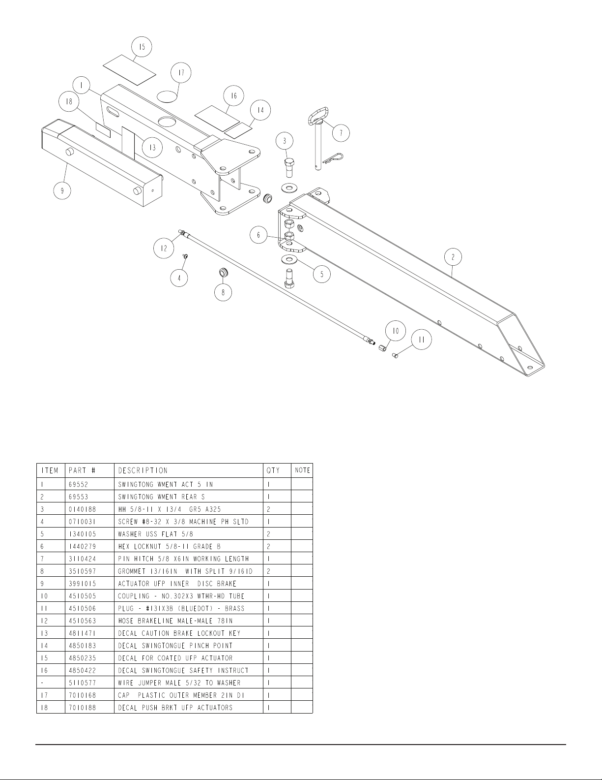
Diagram B
Midwest Industries, Inc. Ida Grove, IA 51445 800.859.3028 www.shorelandr.com 0003685
REV B 02/06/2009
Page 4
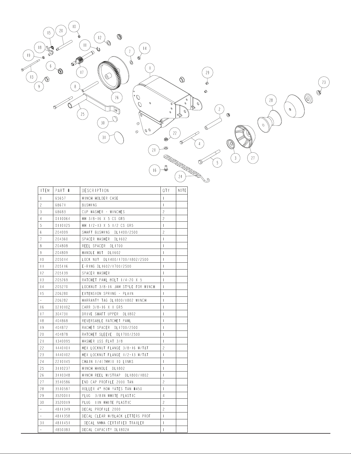
Diagram C
Midwest Industries, Inc. Ida Grove, IA 51445 800.859.3028 www.shorelandr.com 00036853
REV B 02/06/2009
Page 5
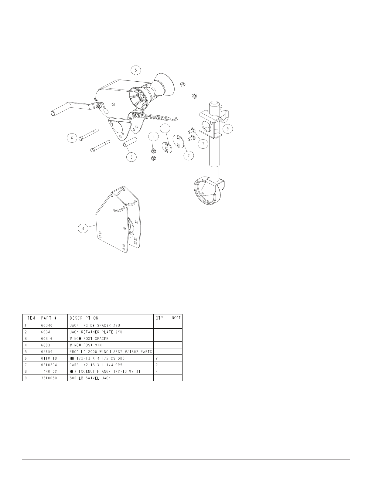
Diagram D
Locate the hardware bag and sort all items by size.
Lay the Prole 2000 winch base on its side so the side that the jack
is going to be mounted on is up.
Place the inside jack spacer on the winch base so the center pro-
trusion ts down into the indent in the winch base.
Position the jack mounting plate so it is centered around the inside
jack spacer just positioned.
Lay the jack retainer plate on top of the jack mounting plate aligning
the holes in it with the holes in the winch base.
Insert the two ½” and 1 ¼” carriage bolts into the holes just aligned
in the jack retainer plate and the winch base. Secure in place with
½” lock washers and hex nuts. Tighten.
Once tightened, rotate the jack through its normal pivoting range to
make sure it is free to travel and is not binding up.
If jack pivots, place it on the tongue and secure in place with the
bolts and hardware provided with the trailer. Complete the assembly of the winch head to the winch base. Assembly is complete.
WINCH POST INSTALLATION
The height that the bow eye is placed in your boat will determine
the length winch post required. Once this is determined, attach the
winch base to the tongue with three 1/2” x 4-1/2” carriage bolts and
lock nuts.
Align the holes in the Prole 2000 mounting channel with the holes
in the top of the winch base. Attach the front of the winch head
mounting channel to the base by placing a 1/2” x 4-1/2” hex bolt
through the hole closest to the front of the winch base. Secure with
a lock nut. Do not tighten.
Note that the winch head can now be rotated either up or down.
Identify the correct hole combination to use to position the bow eye
roller just above the bow eye of your boat. When determined, secure in this position by placing the bushing as shown in Diagram D
inside the winch base so it aligns with the hole just identied for the
proper adjustment. Insert another 1/2” x 4-1/2” hex bolt through the
determined mounting hole in the mounting channel and winch base
making sure the bolt passes through the bushing as well. Secure
with a 1/2” lock nut. Tighten all bolts.
Midwest Industries, Inc. Ida Grove, IA 51445 800.859.3028 www.shorelandr.com 0003685
REV B 02/06/2009
Page 6
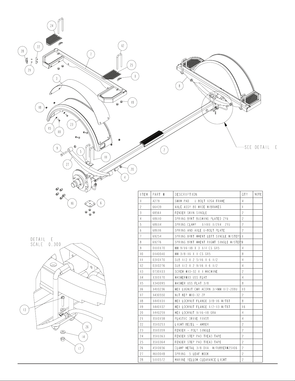
Diagram E
Midwest Industries, Inc. Ida Grove, IA 51445 800.859.3028 www.shorelandr.com 00036853
REV B 02/06/2009
Page 7

Disc Brake Assembly
Tire Size and Carrying Capacity Chart
Tire Size ............................ST215/75R14-C
GVWR ...............................3740 LB.
Carrying Capacity ..............2900 LB.
Axle....................................Single Brake - Standard
Refer to the tire side wall for correct tire pressure.
Midwest Industries, Inc. Ida Grove, IA 51445 800.859.3028 www.shorelandr.com 0003685
REV B 02/06/2009
Page 8

SPRINGS
Position the axle so it is properly aligned with the trailer and the
calipers are on the back side of the axle as shown.
Place the springs on the topside of the spring pads welded to the
axle. (See Diagram E). Note that the hook end of the spring must
be mounted to the rear of the trailer. Place a spring clamp on the
top center of the spring as shown. Next place the 1/2” x 6-1/2”
U-bolts down over the top of the spring clamp, spring and axle as
shown.
Place the spring and axle U-bolt plate onto the ends of the two
U-bolts just placed around the axle. Secure with 1/2” lock nuts.
Thread onto the U-bolts but do not tighten securely until the complete unit is in position on the trailer. Repeat on the other spring.
AXLE
Place one of the spring bracket bushings into the rear of the spring
bracket and secure with a 9/16” x 3-1/4” hex bolt and hex lock nut.
Repeat in other spring bracket.
Position the axle under the frame, then hook the hook loop of the
spring around the bushings just installed. Note that if the axle is
positioned too low when trying to hook, the hooks will not hook
around the bushings.
Raise the front of the springs up so they align with the front hole
of the spring bracket. Secure in place with 9/16” x 3-1/4” hex bolts
and lock nuts.
Tighten all axle U-bolts and spring bolts not tightened at this time.
ONE AXLE BRAKE INSTALLATION
Locate the brake hose coming out of a hole in the inside rear of the
side frame near the axle position. Route the hose over to the axle
and insert it into the larger outer hole in the brake hose mounting
bracket. Route it down to the caliper where it will be attached and
remove the plastic cap covering the threaded connection.
Remove the brass plug from the port in the brass block on the right
brake caliper. Thread the brake hose just routed down from the
side frame into the port where the brass plug was just removed.
Tighten.
Over-tightening will permanently damage the internal components
of the brass tting causing the tting to leak.
Place the rubber grommet around the brake hose and insert it
into the hole in the brake hose mounting bracket. The grommet
will protect the hose from abrasion as well as retain it from sliding down while being towed. Enough slack should be left in the
brake hose from the hose mounting clamp and the axle to allow the
axle to move freely without the hose rubbing on the spring or any
other steel part. All additional hose above the brake hose mounting
clamp and the side frame hole can be pushed back into the side
frame for protection from the elements.
In the event that the axle position is at some distance from the hole
in the side frame where the brake hose is routed from, two additional hose mounting clamps and self-tapping screws are provided
to attach the brake hose to the inside of the side frame. Bend the
open end of the hose mounting clamps open far enough so the
hose can be slide inside the clamp. Once the hose is inside, bend
the clamps back shut so it forms around the brake hose. Position
the two clamps on the inside of the side frame spaced so there is
an equal distance between the hole where the brake hose comes
out of the side frame and the brake hose mounting clamp. Using
the self-tapping screws, drill them into the side frame to secure the
clamps in place. Tighten until the screws are fully in. This will grip
the brake hose and keep it from moving.
All bleeding to the line can be done through the bleeders on the
calipers
Fill the actuator reservoir with brake uid and bleed the line per the
instructions in the brake manual.
TIRE & WHEEL ASSEMBLIES
Mount the tire and wheel assemblies using the 1/2” ne threaded tapered lug nuts provided. Tighten to 85-95 ft/lb. of torque using the rotation pattern as shown in the ShoreLandr’s Owners
Manual. Re-torque the lug nuts after 50 miles of driving and then
periodi¬cally thereafter.
Hand-tighten the tting on the end of the frame brake hose to the
side tting of the brake caliber.
Fit the axle brake hose to the bottom tting on the brake caliber.
Use a wrench to tighten 1/4 turn. Repeat on other side of axle.
Bleed system. If the connection leaks, tighten only enough to stop
the leak.
Midwest Industries, Inc. Ida Grove, IA 51445 800.859.3028 www.shorelandr.com 00036853
REV B 02/06/2009
Page 9

EQUILOAD DOUBLE BUNK ASSEMBLY
Locate the carpeted bunks. Lay two of them upside down on the
oor so they are spaced approximately 3 ½” apart. Remove the
nuts and lock washers from the bolts that are in the bunks.
double bunk brackets drop down around the cross members so
one leg of the brackets is on each side of the cross member. Align
the proper hole in the double bunk brackets with the correct hole
in the cross members. Insert a 3/8” x 3 ¾” hex bolt into the aligned
holes. Secure with a 3/8” ange lock nut. Tighten. Tighten the nuts
Turn the bunk assembly upright and place on the trailer so that the
Locate two of the double bunk brackets. Position them upside down
left slightly loose when assembling the bunks.
so that the holes in the double bunk brackets align with the bolts
from which the nuts were just removed. Drop into position and secure with the lock washers and hex nuts just removed. Tighten but
Repeat the above process on the bunks for the other side of the
trailer.
do not over tighten because they may have to be adjusted to t the
trailer cross members.
Midwest Industries, Inc. Ida Grove, IA 51445 800.859.3028 www.shorelandr.com 0003685
REV B 02/06/2009
Page 10
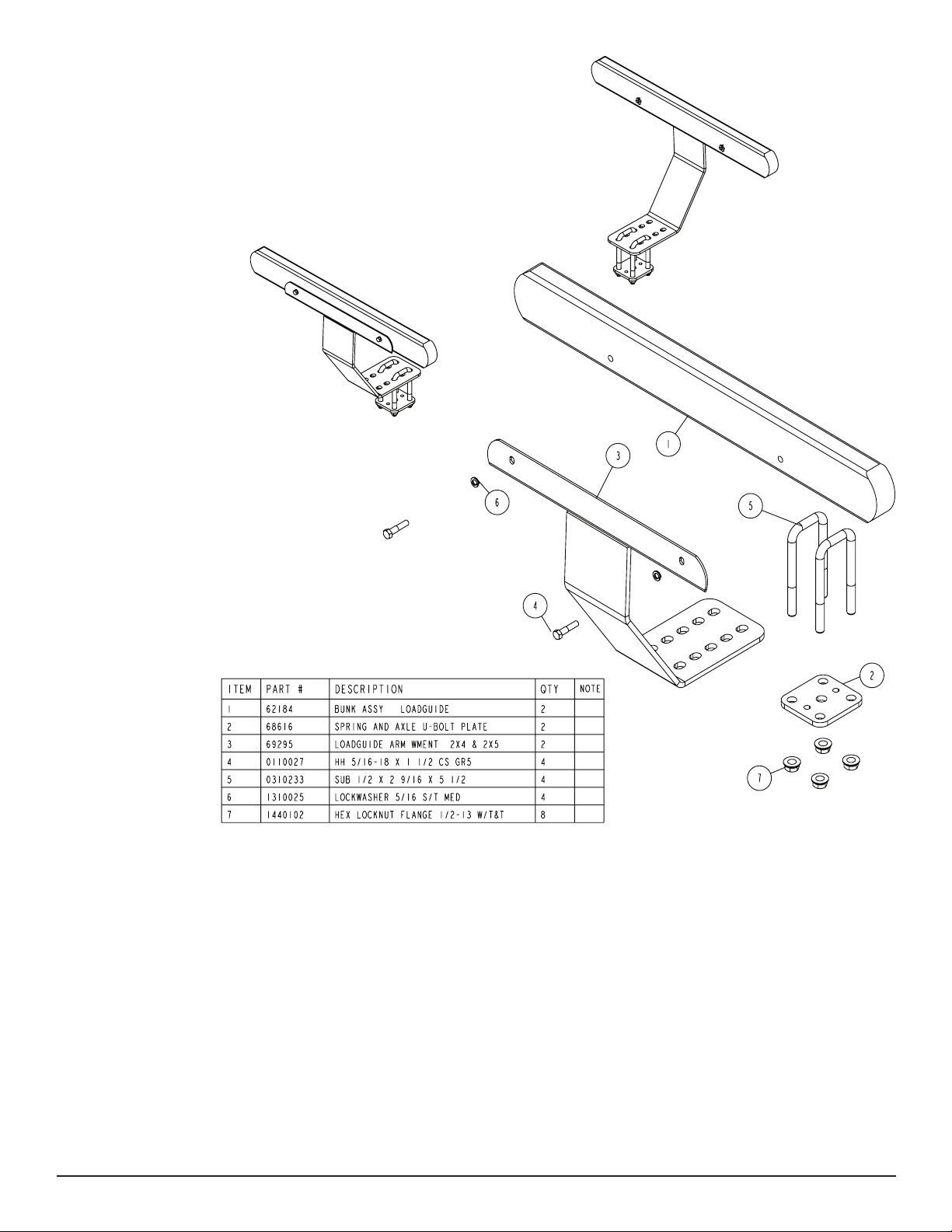
TA0116 Lund Load Assembly Instructions
The TA0116 load guides are designed to t on the Lund
boat trailers manufactured with 2 x 4 side frame tubing .The
length of the mounting U-bolts provided will accommodate
this size tubing only. Mounting on a smaller or larger side
frame tube may not be possible because of the U-bolt
length. .
Remove all items from the box and sort by size.
Locate two of the ½” x 2 9/16” x 5 ½” U-bolts. Drop them
Note that the arm weldments of the load guide are identical
so there is no right or left part.
down through the holes in the arm weldments just identied
as shown in the diagram. Place the U-bolts so one of the
U-bolt legs is on each side of the side frame. Place one
Locate the arm weldments and the carpeted bunks. Attach
the carpeted bunks to the arm weldments using the 5/16” x
of the metal plates provided onto the legs of the U-bolts.
Secure with ½” ange lock nuts.
1 ½” hex bolts and lock washers provided. Tighten.
Slide the load guide forward or backward on the frame until
Make sure the boat is centered on the trailer before attempting to install the load guides.
Position one of the load guide assemblies on the top side of
the side frame and move in or out until the desired clear-
the rear of the load guide does not extend past the rear of
the boat. Tighten the load guide in this position.
Repeat the above process on the load guide for the other
side of the trailer.
ance has been established between the load guide and
the boat. Select the proper pair of holes that you will use to
Assembly is complete.
mount the arm weldments to the side frame.
Midwest Industries, Inc. Ida Grove, IA 51445 800.859.3028 www.shorelandr.com 00036853
REV B 02/06/2009
Page 11

Mounting Instructions:
The rst step in mounting the spare tire bracket is to determine the cor¬rect orientation of the trailer. Standing at the
rear of the trailer and look¬ing forward, your right hand is the
right-hand side of the trailer.
Mount the spare tire bracket on the right-hand side frame of
your trailer at a location somewhere between the very front
of the frame and the rst cross member. The exact positioning is dependant upon the size and style of your boat.
Once identied, attach the spare tire bracket to the side
frame using the U-bolts provided in the kit. Note that the
spare tire bracket is designed to t both 2” x 4” and 2” x
5” side frames. Use the 1/2” x 4-9/16” x 3-1/2” U-bolt when
mounting to the 2” x 4” side frame and the 1/2” x 5-9/16” x 3”
U-bolts when mounting to the 2” x 5” side frame.
Place the U-bolts over the side frame in the desired location.
Match the holes in the spare tire bracket with the U-bolts just
placed over the side frame. Slide the spare tire bracket over
the U-bolts. Secure using 1/2” lock¬ washers and hex nuts.
Tighten when desired location is achieved
in the spare tire bracket which are sufcient to carry the tire
and wheel assembly. Align the three studs with the holes in
the wheel assembly and secure the wheel assembly to the
spare tire bracket with three- 1/2” tapered lug nuts provided
in the kit. Tighten securely to make sure the wheel assem-
bly does not come loose and fall off while transporting the
trailer.
Installation is complete.
NOTE: This spare tire bracket MUST BE
MOUNTED back on the side of the trailer so
that the tire DOES NOT block the front side
marker light. This light MUST be visible 45° to
the rear to comply with Code of Federal Regulations 49CFR571.108 lighting regulations
The spare tire bracket is designed to t a 5 bolt on 4.5” bolt
circle pattern wheel. Note that there are only three stud bolts
Midwest Industries, Inc. Ida Grove, IA 51445 800.859.3028 www.shorelandr.com 0003685
REV B 02/06/2009
Page 12

TRAILER ADJUSTMENTS
The adjustment of the trailer to your boat is very important not only
for the trailer, but also the boat. Failure to do so may lead to potential failure or damage to either the trailer or boat.
Adjust as follows:
AXLE ADJUSTMENT
The amount of tongue weight on your trailer can be adjusted as
follows:
To lower the tongue weight, adjust the axle assembly forward. To
in¬crease the tongue weight, adjust the axle backward.
The distance that the axle assembly has to be moved will vary because it is directly related to the weight and center of gravity of the
boat placed on it.
Best towing is achieved when the tongue weight is 5-7% of the total
gross load of the complete unit.
Wire harnesses and brake line lines will need care when moving
the axle assembly.
REAR SUPPORT SYSTEM
Place the boat on the trailer so that the transom is located at the
rear of the support system. The transom of the boat should be within 1-2” of the end of the bunks.
Bunks
Make sure the bunks are positioned far enough apart to give your
boat as much stability as possible while transporting. Position the
bunks so they are located just to the outside of a strake or else
have the strake located between the bunks. The bunk positioning
is a pre-determined position that will work best for your particular
boat.
WINCH POST
The winch post is pre-adjusted to t the boat. If it does not, use the
following instructions to adjust to properly t your boat.
Once all other adjustments are complete the winch post can be
adjusted. Slide the winch post base backward on the tongue until
the bow roller comes in contact with the boat. This bow roller needs
to be posi¬tioned directly above the boat bow eye to prevent your
boat from moving forward in the event of a sudden stop. It can be
moved up or down by removing the back bolt that mounts the winch
head to the base. When this bolt is removed, the head can be rotat-
ed up or down to reach the desired height required to t your boat.
Once in this position, align the closest pair of holes in the brackets
and reinsert the bolt just removed. Tighten. Attach the winch strap
and crank winch tight. Attach the bow eye safety chain into the bow
eye of the boat as well. This is just another level of protection to
keep your boat and trailer together as one unit.
Check the boat to make sure it is in the desired location forward
and backward on the trailer. If location is as instructed above, tight-
en the three bolts in the winch base securing the winch base to the
tongue.
Once all adjustments are complete and checked, connect to the
tow vehicle to make sure all of the lights are operating properly and
match the tow vehicle.
Re-check all fasteners on the complete trailer to make sure they
are all tight and ready for towing. All fasteners should be periodi-
cally check before towing.
See your ShoreLand’r Owner ’s Guide for further technical
informa¬tion regarding your trailer and its components.
FRONT SUPPORT SYSTEM
Bunks
Adjust the bunks up so that there is approximately 1-2 inches clearance between the keel of the boat and the center cross member
pad.
Midwest Industries, Inc. Ida Grove, IA 51445 800.859.3028 www.shorelandr.com 00036853
REV B 02/06/2009
Page 13

Midwest Industries, Inc. Ida Grove, IA 51445 800.859.3028 www.shorelandr.com 0003685
REV B 02/06/2009
Page 14
 Loading...