

Page 1
®
LIB15
LIRB15 Leisure 1X5 - 1500lbs. Trailer
2 4300184 5.30 X 12-C Tire/MSilver Mod Rim (or)
2 4300206 5.30 X 12-C Tire/Galv Mod Rim
1 62340 Literature Bag - Trailers
1 66620-- Frame Bundle - 1X3 Leisure
1 66625-- Bunk Bundle - Leisure RB1615
Tongue Weight Adjustment
Approximate Tongue Weight for Best Towing.
Tongue weight too high, move the axle assembly forward.
Tongue weight too low, move the axle assembly backward.
Tongue weight should be 5% to 7% of the total gross
weight of the boat and trailer combined.
Tire Size & Carrying
Capacity Chart
Tire Load Carrying
Size Range Capacity
5.30 X 12 C 1045 lb. per/tire
Refer to tire side wall for proper tire pressure.
Final Assembly Instructions
Remove the small parts from the frame by cutting the
bands. Remove the bolt bag and sort all the nuts and bolts
by size.
Axle:
Install the spring busings in the rear spring brackets with 1/
2 X 3-1/4 hex bolt and 1/2 flange lock nuts. Position the
axle under the trailer with the spring eye to the front. Slip
the flat end of the spring in the rear spring bracket and
fasten the front spring eye to the front spring bracket with
9/16 X 3-1/4 hex bolts and 9/16 hex lock nuts. Mount the
tire and rim assemblies with 1/2 lug nuts and tighten to
80-90 ft./lbs. of torque.
Tongue:
Telescope the tongue out and install the tongue cover onto
the tongue frame cap using a 1/2 X 1-1/2 hex bolt.
Secure with a 1/2 flat washer and 1/2 hex nut. Secure the
tongue into the side frame tongue cap using a 1/2 X 4
hex bolt and 1/2 flange lock nut.
Tongue Wires:
Install the tongue wire harness through the top forward
wire hole and exit the rear of the tongue channel on the
frame. Install the grommets and plug the tongue wire into
the frame harness by color codes.
Page 2

Material List for the LIB15
NOTE: ShoreLandr offers their product line in either galvanized or painted finish. When ordering parts it is important that you specify the
finish or color you have on your product. The five digit number along with a two digit space _ _, notes the parts which can be purchased
with various finishes. When ordering these items use the five digit prefix and include the following two digit suffix for proper finish.
Suffix Finish / Color
00 or G Galvanized
01 Arctic White
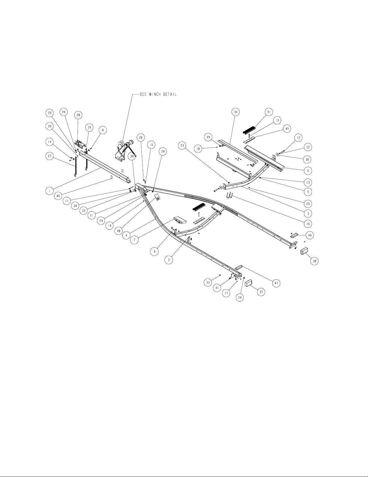
REF# PART# DESCRIPTION QTY
1 60493-- TONGUE 3X3X60 ...................................... 1
2 64511-- ADJ BUNK BRKT - 2 PLACE PWC ........... 4
3 64930-- REAR PIVOT WMENT R1615 ................... 1
4 66094-- FRAME WMENT 64 WIDE 157 LONG ...... 1
5 66611-- BUNK SUPPORT WMENT ........................ 2
6 66624 BUNK 2X4 LEISURE RB1615 ................... 2
7 66719-- BUNK ASSY 2X6X10" W/BRKT ................ 2
8 0110037 HH 3/8-16 X 1 1/4 CS GR5 ........................ 2
9 0110054 HH 3/8-16 X 3 CS GR5 .............................. 4
10 0110096 HH 1/2-20 X 1-1/2 ...................................... 1
11 0110114 HH 1/2-13 X 4 CS GR5 .............................. 2
12 0120189 HH 5/8-18 X 3 1/2 CS GR5 ........................ 2
13 0140040 HH 3/8-16 X 1 CS GR5 .............................. 8
14 0140090 HH 1/2-13 X 1 CS GR5 .............................. 2
15 0210130 CARR 3/8-16 X 3 3/4 GR5 ......................... 2
16 0310103 SUB 3/8 X 2 7/16 X 4 ................................. 4
17 0810126 SCREW SELFTAP TYPE B 1/4X1/2 ......... 4
18 0810930 SCREW SELFTAP #10-12X1 1/4 TYPE A 16
19 0810945 SCREW SELFDRILL 1/4-14X3/4 .............. 1
20 1340095 WASHER USS FLAT 3/8 ........................... 4
21 1340100 WASHER USS FLAT 1/2 ........................... 1
22 1340105 WASHER USS FLAT 5/8 ........................... 2
23 1410125 HEX LOCKNUT 5/8-18 GRB ..................... 2
24 1410209 HEX LOCKNUT 1/2-20 .............................. 1
25 1440101 FLANGE LOCKNUT SMALL 3/8-16 .......... 24
REF# PART# DESCRIPTION QTY
26 1440102 FLANGE LOCKNUT SMALL 1/2-13 .......... 4
27 2210155 CHAIN 3/16X20 LINK CHAIN .................... 2
28 3310010 COUPLER #980 P2 ASSEMBLED ............ 1
29 3510030 GROMMET 7/8IN MOLDED ..................... 5
30 3510122 LIGHT BEZEL - WHITE ............................. 2
31 3510132 AXLE PAD 12IN BLK ................................ 2
32 3510158 PLASTIC DRIVE RIVOT ............................ 4
33 3520017 PLUG 11/16IN WHITE PLASTIC ............. 2
34 3910045 BUNKWOOD 2 X 4 X 8FT FIR ................ 2
35 3910170 CARPET 60 IN WIDE BLACK ................... 4
36 4811338 WASHER NYLON-1" ID X 3" OD X 0.030 . 2
37 5110013 DRY LAUNCH LIGHT ASSY (LEFT) ......... 1
38 5110014 DRY LAUNCH LIGHT ASSY (RIGHT) ....... 1
39 5110112 MARINE YELLOW CLEARANCE LIGHT .. 2
40 5110127 REFLECTOR ANDERSON AMBER .......... 2
41 5110348 BO LICENSE PLATE BRACKET ............... 1
42 5110349 HARNESS TONGUE 7FT ........................ 1
43 5110410 HARNESS FRAME LEFT JET BOAT ...... 1
44 5110411 HARNESS FRAME RIGHT JET BOAT ... 1
45 S-3387 2" PLASTIC CHANNEL BRACKET ........... 2
46 S-3390 STEP PAD RIGHT 2 1/2 X 7 .................. 1
47 S-3391 STEP PAD LEFT 2 1/2 X 7 ..................... 1
48 S-3546 TONGUE COVER PLATE ......................... 1
49 S-3442G 2X4 BUNK BRKT ....................................... 4
DECALS:
4850360 DECAL NMMA CERTIFIED TRAILER ...... 1
4811333 DECAL BLACK ARROW ........................... 1
4811372 DECAL ABCD WINCH BLACK/CLEAR ..... 1
4811329 DECAL WINCH ADJUSTMENT ................. 1
4810709 DECAL TRAILER CAUTION/WARN ......... 1
ASSEMBLIES AND/OR OPTIONS:
60602-- WINCH ASSEMBLY 1400 - 62
65062-- AXLE ASSEMBLY
66622 HARDWARE BAG - LEISURE
66623-- TONGUE ASSEMBLY FOR LEISURE
S-3553 BUNK ASSEMBLY 2X6X10 W/BRACKET
Page 3
0002760
Parts Drawing
NOTE: Optional equipment
and replacement parts must be
purchased through an authorized ShoreLandr dealer.
CHASSIS DETAIL REFER TO DOCUMENT -
0002759
Page 4

Safety Chain:
Insert a 3/8 x 1-1/4 hex bolt with a 3/8 flat washer and
safety chain through the lower hole on the front of the
tongue. Secure with a 3/8 flat washer and 3/8 flange lock
nut. Repeat this procedure on teh opposite side of the
tongue.
Coupler:
Mount the coupler onto the tongue with one (1) 1/2 X 4
hex bolt into the rear hole on the coupler and tongue.
Using two (2) 1/2 X 1 hex bolts into the two (2) front holes
on the coupler and tongue. Secure with 1/2 flange lock
nuts.
Winch Post:
NOTE: The law requires that the white ground wire on
both the tongue wire harness and the vehicle harness
be properly grounded to the respective trailer and
vehicle frames.
Adjustment Instructions
Bunk Adjustment:
Place your water craft on the trailer. Determine the spacing
on the bunk support channels. It maybe necessary to
adjust your bunk support channels in or out from the
position you have it assembled. The bunks must be
adjusted to miss any keel or strake which might be on your
particular water craft.
Secure the winch post to the tongue with three (3) 3/8 X 4
hex bolts and 3/8 flange lock nuts. Mount the winch
handle to the winch using the special nut provided. Tighten
the winch post in a location that best fits your water craft.
Bunk:
Mount the bunk support weldment to the rear pivot in a
location that best fits your water craft. Fasten to the rear
pivot using two (2) 3/8 X 2-7/16 X 4 square u-bolts per
side. Tighten with 3/8 flange lock nuts. Mount the bunks to
the bunk support weldment using 3/8 X 1 hex bolts and 3/
8 flange lock nuts.
Assembly should be complete except for tightening
some of the bolts. These bolts were left loose to aid in
adjusting the trailer to the boat only. All bolts and nuts
must be tightened before towing.
IMPORTANT: The bunk assembly should be spaced as far
apart as possible for stability. This in most cases will also
allow your water craft to be as low as possible on the
trailer for better trailering, loading and unloading.
Once the bunk assemblies have been spaced properly for
your water craft, position the water craft on the trailer with
transom flush with the rear of the bunk assemblies.
Winch Post Adjustment:
Once the water craft is positioned on the trailer, adjust the
winch post to the water craft. Adjust the bow stop bracket
so that the rubber bow stop is just above the bow eye.
Note: Double check all fasteners and tighten before
towing.
Made in the USA Midwest Industries, Inc. Ida Grove, IA 51445 (800)859-3028 0002887
www.shorelandr.com REV A 9/13/00
Page 5

®
Winch Assembly - 60602--
REF# PART# DESCRIPTION QTY
1 3340 OUTSIDE WINCH CHANNEL .................. 1
2 3382 WINCHSTAND INSIDE CHANNEL ........ 1
3 0110060 HH 3/8-16 X 4 CS GR5 ............................. 3
4 0120130 HH 1/2-13 X 6 1/2 CS GR5 ....................... 1
5 0140045 HH 3/8-16 X 1 1/2 CS GR5 ....................... 2
6 0220110 CARR 3/8-16 X 1 1/2 FULL THRD GR5 ... 1
7 1310165 WASHER 1.377 OD X .390 ID .................. 2
8 1340095 WASHER USS FLAT 3/8 ........................... 5
9 1440101 FLANGE LOCKNUT SMALL 3/8-16 .......... 6
10 1440102 FLANGE LOCKNUT SMALL 1/2-13 .......... 1
11 2210145 CHAIN 1/4(7MM)X 10 LINKS .................... 1
12 3110217 WINCH DL1402 W/20 FT STRAP ............. 1
13 3510062 3-1/2 OD X 1/2 ID END CAP ................... 2
14 3510065 4" BOW ROLLER - BLACK ....................... 1
15 4810709 DECAL TRAILER CAUTION AND WARN 1
16 4850360 DECAL NMMA CERTIFIED TRAILER ...... 1
17 S-3333 WINCHGUIDE PIN 3/8 ZYU ................... 1
18 S-3334 WINCH STRAP GUIDE CHANNEL ZYU . 1
19 S-3346 NYLON BUSHING ..................................... 1
Secure the winch post to the tongue with three (3) 3/8 X 4 hex
bolts and 3/8 flange lock nuts. Mount the winch handle to the
winch using the special nut provided. Tighten the winch post in a
location that best fits your water craft.
Winch Post Adjustment:
Once the boat is postioned on the trailer, adjust the winch post to
the boat. Adjust the bow stop bracket so that the rubber bow stop
is just above the bow eye.
Made in the USA Midwest Industries, Inc. Ida Grove, IA 51445 (800)859-3028 0002760
www.shorelandr.com REV - 6/01/00
Page 6

Page 7

®
Chassis - 15/15A
REF# PART# DESCRIPTION QTY
1 6240610 FENDER SUPPORT BRKT ...................... 4
2 62780-- SPRING BRACKET BOLT ON .................. 2
3 65060-- AXLE WMENT (64 WIDE FISHING) ......... 1
4 0110107 HH 1/2-13 X 3 CS GR5 ............................. 2
5 0110170 HH 9/16-18 X 3 1/4 CS GR5 ..................... 2
6 0120052 HH 3/8-16 X 2 3/4 CS GR5 ....................... 4
7 0210102 CARR 3/8-16 X 1 GR5 .............................. 1
8 0310060 SUB 3/8-16 X 2 3/16 X 1 3/4 ..................... 4
9 1340095 WASHER USS FLAT 3/8 ........................... 4
10 1340206 WASHER 1.5 OD X .765 ID X .186/.206 .. 2
11 1410230 HEX LUGNUT 1/2-20 3/4 OD Z&U ........... 10
12 1440101 FLANGE LOCKNUT SMALL 3/8-16 .......... 13
13 1440102 FLANGE LOCKNUT SMALL 1/2-13 .......... 2
14 1440259 HEX LOCKNUT 9/16-18 GRA ................... 2
15 1440349 HEX NUT SLOTTED PLAIN ..................... 2
16 1540038 COTTER KEY 1/8 X 1 1/2 ......................... 2
17 3510123 FENDER FISHING TADPULL POLY ....... 2
18 3510132 AXLE PAD 12IN BLK ................................ 1
19 4300206 5.30X12 C TIRE/GALV MOD RIM ............. 2
-- 4300184 5.30 X 12 C TIRE/MSILVER MOD RIM .... 2
-- 4300209 ST155/80R13C TIRE/GALV DIR RIM ....... 2
-- 4300210 ST155/80R13C TIRE/MSILVER DIR RIM 2
REF# PART# DESCRIPTION QTY
20 4410087 SPINDLE SLEEVE - 1 1/16 ....................... 2
21 4410247 BEARING BUDDY - STAINLESS STEEL . 2
22 4410275 SEAL .......................................................... 2
23 4440160 ROLLER BEARING 1 1/16IN .................. 4
24 4470337 HUB 1 1/16 X 1 1/16 CAST ..................... 2
25 4610010 SLIPPER LEAF SPRING .......................... 2
26 S-2029 SPRING BUSHING SPACER ................... 2
27 S-3387 2" PLASTIC CHANNEL BRACKET ........... 1
Place one of the spring bushings (Ref.#26) into the rear of the
spring bracket (Ref.#2) and secure with a 9/16 X 3-1/4 hex bolt
(Ref.#5) and 9/16 hex lock nut (Ref.#14). Repeat on the other
side. Position the axle (Ref.#3) under the frame, then hook the
spring loop around the bushing just installed. Raise the axle
assembly up so the front of the springs (Ref.#25) line up with the
front spring bracket hole. Insert the other two (2) 9/16 X 3-1/4 hex
bolts and 9/16 hex lock nuts. Tighten all nuts and bolts, but do not
over tighten. Allow the spring room enough to move.
Mount the tires and rim assemblies (Ref.#19) using 80-90 ft. lbs.
tongue on lug nuts (Ref.#11) using proper tightening procedures.
Tire Size & Carrying Capacity Chart
Chassis Tire Load Carrying
Size Range Capacity
15 5.30 X 12 C 1045 lbs. per/tire
15A ST155X80R13 C 1100 lbs. per/tire
Refer to the tire side wall for the correct tire pressure.
Made in the USA Midwest Industries, Inc. Ida Grove, IA 51445 (800)859-3028 0002759
www.shorelandr.com
REV - 6/01/00
Page 8

 Loading...