

Page 1
LEB40TCBBXLW-01, LEB40TCBBXLW-03, LEB40TCBBXLW-08,
®
LEB40TCBBXLW-14 & LEB40TCBBXLW-22
LEB40TCBBXLW (All Colors) Bundles Required:
ST215/75R14C OWL Tire/ Aluminum Star Rim ........ 4
(or)
ST215/75R14C OWL Mod Tire/Chrome w/Rivets
Rim ........................................................................... 4
66520 Bag with Chains, No Coupler .................................. 1
69082 Literature Bag - Trailers - Brakes.............................. 1
80132-- Frame Bundle - LEB40TCBBXLW ............................ 1
67287-- Swing Tongue Assembly 65”, Disc Brake ................. 1
TA0028-__ Spare Tire Kit 2X4/5” Frames - 5 Bolt....................... 1
69352 Brake Kit TAndem Axle - Connect Hose ................... 1
Midwest Industries, Inc. Ida Grove, IA 51445 800.859.3028 www.shorelandr.com 0003288
Page 1
ShoreLand’r offers their product line a painted nish. When ordering
parts it is important that you specify the nish or color you have on
your product. The ve (5) digit number along with a two (2) digit space
_ _, note the parts which can be purchased with various nishes.
When ordering these items use the ve (5) digit number along with
a two (2) digit sufx for the proper nish.
01..........Arctic White
03..........Black
08..........Pearl White
14..........Blue
22..........Red
Tire Size and Carrying Capacity Chart
Tire Size ST215/75R 14-C
GVWR 5440 lb.
Carrying Capacity 4000 lb.
Axle Brake
Refer to the tire side wall for correct tire pressure.
REV C 1/04/07
Page 2
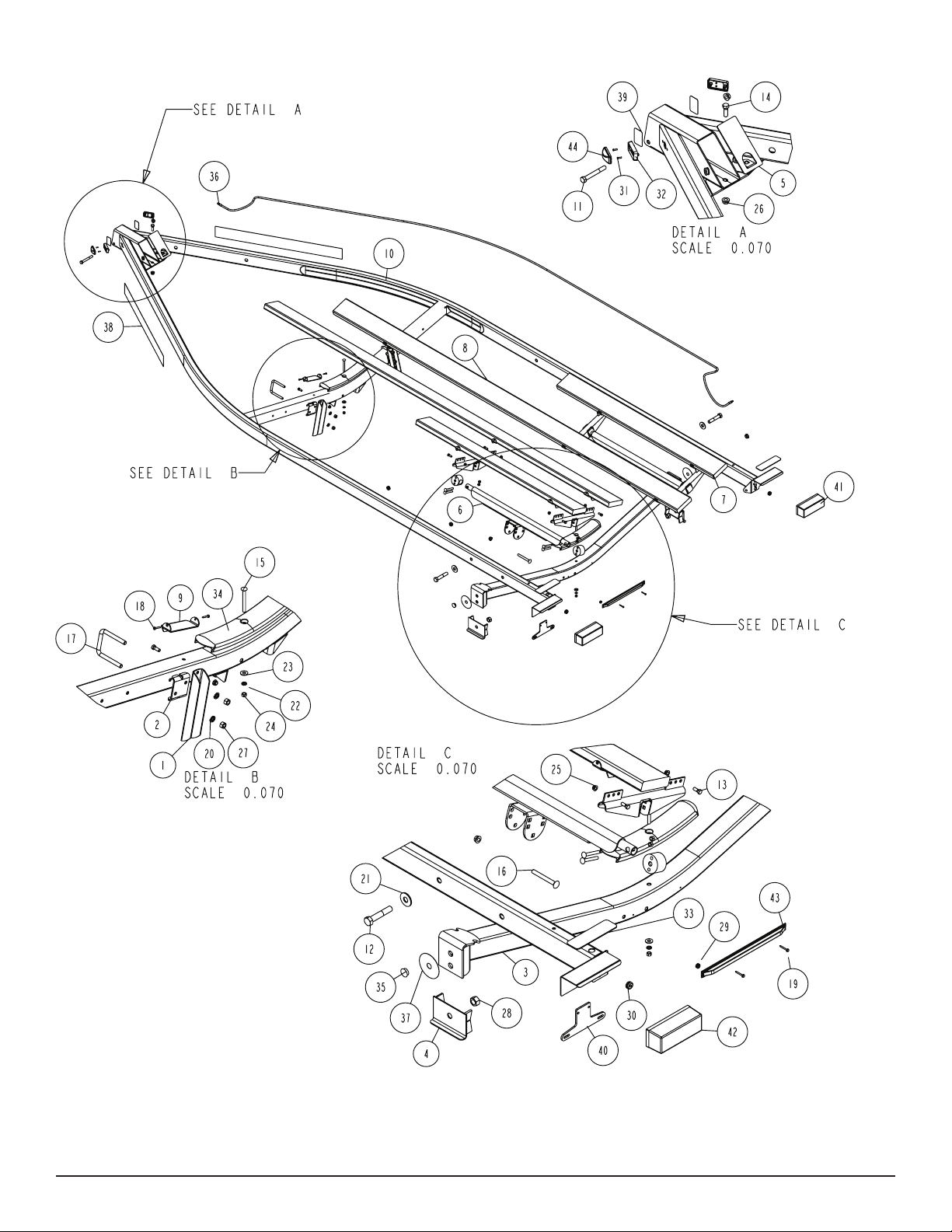
Diagram A
Midwest Industries, Inc. Ida Grove, IA 51445 800.859.3028 www.shorelandr.com 0003288
Page 2
REV C 1/04/07
Page 3
Refer to your ShoreLand’r Owner’s
Guide and other decals on trailer for
additional information.
SAFETY INSTRUCTIONS
4810709
Proper tongue weight must be maintained.
Rev C 8/28/06
Before towing, check the following to ensure
that:
1. All parts, bolts, nuts and wheel lug
nuts are tight.
2. All wheel lug nuts must be tightened
to a minimum torque rating of 85 ft/lb.
3. Lug nuts must be re-torqued after the
first 50 miles, then periodically there
after.
4. Tires are inflated to manufacturer’s
standards. (See tire sidewall)
5. Wheel bearings have adequate
grease.
6. Hitch ball is the proper diameter and
has a rating equal to or greater than
the GVWR of the trailer.
7. Coupler is properly attached and
secured to coupler ball.
8. Trailer safety chains are crossed
under the tongue and attached to
towing vehicle.
9. All lights are operational. Note: It is
recommended that the trailer lights
be disconnected before backing into
the water.
10. Tie downs, winch strap and bow eye safety chain are secure.
11. Trailer tongue jack is in up or travel
position.
Midwest Industries, Inc. Ida Grove, IA 51445 800.859.3028 www.shorelandr.com 0003288
Page 3
REV C 1/04/07
Page 4
Diagram B
Midwest Industries, Inc. Ida Grove, IA 51445 800.859.3028 www.shorelandr.com 0003288
Page 4
REV C 1/04/07
Page 5

FINAL ASSEMBLY INSTRUCTIONS
Remove the hardware bag from the frame. Remove the parts and
sort by size.
TONGUE
The tongue is shipped separate of the frame. Locate the
appropriate tongue and install by sliding it in the front of the
tongue channel.
Line the holes in the tongue with the holes in the tongue channel.
Install the 1/2” x 4” hex bolt in the front cross hole and secure with
a 1/2” lock nut.
Remove the wire harness from the rear of the tongue. Place the
wire harness and the brake line (If equipped with brakes) through
the hole provided in the tongue cover plate. (See Detail F).
Secure the tongue cover plate in position with the same 1/2” x 11/2” hex bolt that secures the back on the tongue to the tongue
channel of the frame. Secure with a 1/2” lock nut. Tighten both
bolts just installed.
Plug the tongue wire harness ends into the frame harnesses by
matching colors and ends. Push the extra wire provided either
into the rear of the tongue or else remove the grommet in the
side frame and place the extra wire in the side frame. Replace
grommet just removed.
SAFETY CHAINS
Locate the 1/2” x 5” hex bolt. Slip the bolt through a 1/2” at washer, then
place through the last link of one of the safety chains provided.
Place the bolt with chain attached through the hole provided in the
bottom front of the actuator mount on the tongue. Place the second
chain on the portion of the bolt extending through the other side
of the tongue. Place on another 1/2” at washer and hex lock nut.
Tighten.
TONGUE BRAKE HOSE CONNECTION
Locate the brass brake line coupling. Remove the plastic cap from
the tting on the end of the tongue hose. Thread into one end of the
coupling. Remove the hose from the side frame enough to reach
into the rear of the tongue. Remove the plastic cap from the tting
on the side frame hose, then thread into the other end of the coupling. Tighten.
Push the excess hose back inside the tongue so that the coupling
just installed is located inside the rear of the tongue.
Midwest Industries, Inc. Ida Grove, IA 51445 800.859.3028 www.shorelandr.com 0003288
Page 5
REV C 1/04/07
Page 6

TA0028-__
SPARE TIRE BRACKET
The rst step in mounting the spare tire bracket is to determine the correct orientation of the trailer. Standing at the rear of the trailer and looking forward, your right hand is the right-hand side of the trailer.
Place the U-bolts over the side frame in the desired location. Match
the holes in the spare tire bracket with the U-bolts just placed over
the side frame. Slide the spare tire bracket over the U-bolts. Secure
using 1/2” lockwashers and hex nuts. Tighten when desired loca-
tion is achieved.
Mount the spare tire bracket on the right-hand side frame of your
trailer at a location somewhere between the very front of the frame
and the rst cross member. The exact positioning is dependant
upon the size and style of your boat.
The spare tire bracket is designed to t a 5 bolt on 4.5” bolt circle
pattern wheel. Note that there are only three stud bolts in the spare
tire bracket which are sufcient to carry the tire and wheel assem-
bly. Align the three studs with the holes in the wheel assembly and
Once identied, attach the spare tire bracket to the side frame using
the U-bolts provided in the kit. Note that the spare tire bracket is de-
signed to t both 2” x 4” and 2” x 5” side frames. Use the 1/2” x 4-9/16”
x 3-1/2” U-bolt when mounting to the 2” x 4” side frame and the 1/2”
secure the wheel assembly to the spare tire bracket with three- 1/2”
tapered lug nuts provided in the kit. Tighten securely to make sure
the wheel assembly does not come loose and fall off while trans-
porting the trailer.
x 5-9/16” x 3” U-bolts when mounting to the 2” x 5” side frame.
Installation is complete.
Midwest Industries, Inc. Ida Grove, IA 51445 800.859.3028 www.shorelandr.com 0003288
Page 6
REV C 1/04/07
Page 7

Diagram C
Midwest Industries, Inc. Ida Grove, IA 51445 800.859.3028 www.shorelandr.com 0003288
Page 7
REV C 1/04/07
Page 8

WINCH POST ASSEMBLY
The height that the bow eye is placed in your boat will determine
the length winch post required. Once this is determined, attach
the winch base to the tongue with three 1/2” x 4-1/2” carriage
bolts and lock nuts.
Align the holes in the Prole 2000 mounting channel with
the holes in the top of the winch base. Attach the front of
the winch head mounting channel to the base by placing a
1/2” x 4-1/2” hex bolt through the hole closest to the front of
the winch base. Secure with a lock nut. Do not tighten.
Note that the winch head can now be rotated either up or down.
Identify the correct hole combination to use to position the bow eye
roller just above the bow eye of your boat. When determined, secure in this position by placing the bushing as shown in Diagram C
inside the winch base so it aligns with the hole just identied for the
proper adjustment. Insert another 1/2” x 4-1/2” hex bolt through the
determined mounting hole in the mounting channel and winch base
making sure the bolt passes through the bushing as well. Secure
with a 1/2” lock nut. Tighten all bolts.
Midwest Industries, Inc. Ida Grove, IA 51445 800.859.3028 www.shorelandr.com 0003288
Page 8
REV C 1/04/07
Page 9

Recommended carrying capacity is based on shipping weight of the trailer with standard equipment. Adding optional equipment
may decrease the trailer’s carrying capacity.
Midwest Industries, Inc. Ida Grove, IA 51445 800.859.3028 www.shorelandr.com 0003288
Page 9
REV C 1/04/07
Page 10

Diagram D
Midwest Industries, Inc. Ida Grove, IA 51445 800.859.3028 www.shorelandr.com 0003288
Page 10
REV C 1/04/07
Page 11

ROCKER ARMS
Locate the rocker arms (Ref. No. 5 Detail B, Diagram D). Note that
the center bushing has a grease zerk in it. Position the rocker arms
up into the center channel welded in the center of the tandem spring
bracket so that the grease zerk is pointing down. Align the holes in
the channel with the rocker arm. Secure in place with a
3/4” x 4-1/2” hex bolt and lock nut. Tighten. Repeat this process on
the other rocker arm and spring bracket. Grease the rocker at this
time by applying grease through the zerk just discussed.
NOTE: The grease zerk is positioned down so that it is
accesible for servicing when needed.
SPRINGS
Position the axles so they are properly aligned with the trailer. Position the brake axle so that the disc brake calipers are on the backside of the axle. The brake axle must always be mounted as the rear
axle to give you the best braking possible. There is no right and left
to the axle without brakes. It can be mounted either way.
Place the springs on the topside of the spring pads welded to the
axle. (See chassis diagram). Note that the hook end of the spring
must be to the rear of the trailer. Place a spring clamp on the top center of the spring as shown. Next place the 1/2” x 6-1/2” U-bolts down
over the top of the spring clamp, spring and axle as shown.
Place the spring and axle U-bolt plate onto the ends of the two Ubolts. Secure with 1/2” lock nuts. Thread onto the U-bolts but do not
tighten securely until the complete unit is in position on the trailer.
Repeat on the other spring.
AXLE
Place one of the spring bracket bushings into the rear
of the spring bracket and secure with a 9/16” x 3-1/4”
hex bolt and hex lock nut. Repeat in other spring bracket.
Position the rear axle under the frame, then hook the hook loop
of the spring around the bushings just installed. Note that if the
axle is positioned too low when trying to hook, the hooks will not
hook around the bushings.
Raise the front of the springs up so they align with the rear hole in
the axle boogie just installed. Attach with 9/16” x 3-1/4” hex bolts
and lock nuts.
Next install another spring bracket bushing in the front hole on the
rock arm assembly. Attach with a 9/16” x 3-1/4” hex bolt and lock
nut. Tighten.
Hook the hook end of the springs mounted to the front axle over
the bushing just installed in the rocker arm assembly. Then swing
the front of the spring up and attach the front mounting hole in the
spring bracket with another 9/16” x 3 -1/4” hex bolt and lock nut.
Tighten all axle U-bolts and spring bolts not tightened at this time.
ONE AXLE BRAKE INSTALLATION
Cut the tape securing the brake line hose to the axle. Remove the
brass plug from the port in the brass block on the right brake caliper. Thread in the brake hose male end and tighten. Place the other
end of the hose up through the hole provided in the brake line clip
bracket. Secure in place with the hose clip provided. (Item No. 65.)
Remove the plastic cap from the end of the frame brake line tubing
coming out of the side frame exit hole. Carefully uncoil the brake
line so that it will reach the end of the hose just attached to the
brake line clip bracket. Thread the brake line tting into the brake
line hose. Tighten. All bleeding to the line can be done through the
bleeder on the right caliper.
ATTACHING AXLE HOSE TO SPRING PLATE
It is important that the brake hose on each end of the axle be at-
tached to the spring plate to eliminate the loops that are formed in
the hose when it is attached to the calipers. Doing so will eliminate
the possibility of the hose getting caught or damaged while tow-
ing.
Locate one of the hose clamps. Spread open the clamp so it can be
slipped around the hose in the loop that is formed under the spring
as it is routed to the caliper. Once in position, squeeze the clamp
back together.
Raise the hose clamp and the loop up until the hose clamp is on top
of the spring bracket raising the loop up so it is on the back side of
the axle. Align the hole in the clamp with the hole in the rear of the
spring bracket between the two U-bolts.
Place a No. 10 at washer on a No. 10 x 1” machine bolt. Insert the
bolt into the clamp, then down through the spring bracket. Place
on another No. 10 at washer and secure with a No. 10 hex nut.
Tighten.
Repeat this process on the other loop on the other end of the axle.
Please refer to the following web address for more information:
h t t p : / / w w w . s h o r e l a n d r . c o m / p a g e s / o _ m a n u a l /
AxleBrakeLineServiceBulletin.pdf
FRAME BRAKE LINE
Place the rubber grommet around the brake hose and insert it
into the hole in the brake hose mounting bracket. The grommet
will protect the hose from abrasion as well as retain it from slid-
ing down while being towed. Enough slack should be left in the
brake hose from the hose mounting clamp and the axle to allow the
axle to move freely without the hose rubbing on the spring or any
other steel part. All additional hose above the brake hose mounting
clamp and the side frame hole can be pushed back into the side
frame for protection from the elements.
In the event that the axle position is at some distance from the hole
in the side frame where the brake hose is routed from, two addi-
tional hose mounting clamps and self-tapping screws are provided
to attach the brake hose to the inside of the side frame. Bend the
hose mounting clamps open far enough so the hose can be slid in-
side the clamp. Once the hose is inside, bend the clamps back shut
so it forms around the brake hose. Position the two clamps on the
inside of the side frame spaced so there is an equal distance be-
tween the hole where the brake hose comes out of the side frame
and the brake hose mounting clamp. Using the self-tapping screws,
drill them into the side frame to secure the clamps in place. Tighten
until the screws are fully in. This will grip the brake hose and keep
it from moving.
All bleeding to the line is to be done through the bleeders on the
calipers.
Fill the actuator reservoir with brake uid and bleed the line per the
instructions in the brake manual.
Midwest Industries, Inc. Ida Grove, IA 51445 800.859.3028 www.shorelandr.com 0003288
Page 11
REV C 1/04/07
Page 12

DUAL AXLE BRAKE INSTALLATION
If your trailer is equipped with dual axle brakes connect the line to
the axle as follows:
Cut the tape securing the brake line hose to the axle. Remove the
brass plug from the port in the brass block on the right brake caliper. Thread the brake hose male end into the block and tighten.
Attach the brake hoses from the axles to the spring bracket with the
brake line clip brackets as shown in Diagram D. Once the brake
hoses are secured in place with the hose clips (Ref. No. 65) the
lines can be attached.
Identify which brake line hose that the side frame brake line tubing
will be connected to. In a dual axle installation it can connected to
either one. When identied, locate the brass tee connector. Screw
the male port of the tee into a brake line hose. Tighten. Next connect the side frame brake line into the top port on the tee. Connect
the two axles together using the 40” brake line supplied. Thread
one end of the line into the brass tee just installed. Route the line
over to the other axle, form a loop in the line and then connect the
other end into the brake line hose for the second axle.
Fill the actuator reservoir with brake uid and bleed the line per the
instructions in the brake manual. Note that the axle is already bled
at the factory during assembly. All bleeding to the line can be done
through the bleeder on the right caliper.
ATTACHING AXLE HOSE TO SPRING PLATE
It is important that the brake hose on each end of the axle be attached to the spring plate to eliminate the loops that are formed in
the hose when it is attached to the calipers. Doing so will eliminate
the possibility of the hose getting caught or damaged while towing.
In the event that the axle position is at some distance from the hole
in the side frame where the brake hose is routed from, two addi-
tional hose mounting clamps and self-tapping screws are provided
to attach the brake hose to the inside of the side frame. Bend the
hose mounting clamps open far enough so the hose can be slid in-
side the clamp. Once the hose is inside, bend the clamps back shut
so it forms around the brake hose. Position the two clamps on the
inside of the side frame spaced so there is an equal distance be-
tween the hole where the brake hose comes out of the side frame
and the brake hose mounting clamp. Using the self-tapping screws,
drill them into the side frame to secure the clamps in place. Tighten
until the screws are fully in. This will grip the brake hose and keep
it from moving.
All bleeding to the line is to be done through the bleeders on the
calipers.
Fill the actuator reservoir with brake uid and bleed the line per the
instructions in the brake manual.
TIRE AND WHEEL ASSEMBLIES
Mount the tire and wheel assemblies using the 1/2” ne threaded
tapered lug nuts provided. Tighten to 80-90 ft/lb. of torque using the
rotation pattern as shown in the ShoreLandr’s Owners Manual.
Re-torque the lug nuts after 50 miles of driving and then periodi-
cally thereafter.
Locate one of the hose clamps. Spread open the clamp so it can be
slipped around the hose in the loop that is formed under the spring
as it is routed to the caliper. Once in position, squeeze the clamp
back together.
Raise the hose clamp and the loop up until the hose clamp is on top
of the spring bracket raising the loop up so it is on the back side of
the axle. Align the hole in the clamp with the hole in the rear of the
spring bracket between the two U-bolts.
Place a No. 10 at washer on a No. 10 x 1” machine bolt. Insert the
bolt into the clamp, then down through the spring bracket. Place
on another No. 10 at washer and secure with a No. 10 hex nut.
Tighten.
Repeat this process on the other loop on the other end of the axle.
Please refer to the following web address for more information:
h t t p : / / w w w . s h o r e l a n d r . c o m / p a g e s / o _ m a n u a l /
AxleBrakeLineServiceBulletin.pdf
FRAME BRAKE LINE
Place the rubber grommet around the brake hose and insert it
into the hole in the brake hose mounting bracket. The grommet
will protect the hose from abrasion as well as retain it from sliding down while being towed. Enough slack should be left in the
brake hose from the hose mounting clamp and the axle to allow the
axle to move freely without the hose rubbing on the spring or any
other steel part. All additional hose above the brake hose mounting
clamp and the side frame hole can be pushed back into the side
frame for protection from the elements.
Midwest Industries, Inc. Ida Grove, IA 51445 800.859.3028 www.shorelandr.com 0003288
Page 12
REV C 1/04/07
Page 13

B-SERIES BUNK ASSEMBLY
Locate the two short and two long 2 x 6 bunk assemblies. The long
bunks are to be mounted to the inside of the rear mounting arms
and attach to the front cross member with the brackets provided
while the short bunks will attach to the rear mounting arm only.
(See Diagram A on page 2). Note that the bunk mounting brackets
are assembled to the bunks at the factory. Place the end of the
long bunk assemblies with the two brackets towards the rear of the
trailer. Place the assembly on the equiload bunk arm and secure
by placing a 3/8” x 1” hex bolt through the bracket on the bunk and
the ear on the end of the equiload arm. Secure in place using a 3/8”
lock nut. Repeat on the other end of the arm. (See Diagram A). Do
not tighten until assembly is complete.
Place the other end of the bunk in the bracket installed on the front
cross member. Note that this bracket is not attached to the bunk
because the trailer can be adjusted to two different lengths. Once
the proper position for the rear cross member is determined, the
front of the bunk can now be attached to the bracket using two- No.
10 x 1-1/4” self tapping screws as shown in Detail C.
Attach the two short bunk assemblies to the outside of the rear
equiload arms using 3/8” x 1” hex bolts similar to the long inside
bunks.
The 3/8”x 1” bolts attaching the bunks to the equiload arms and
front bunk bracket can be tightened but not over tightened because the bunks should be allowed to rotate slightly to conform to the boat bottom once the boat is set on the trailer.
Midwest Industries, Inc. Ida Grove, IA 51445 800.859.3028 www.shorelandr.com 0003288
Page 13
REV C 1/04/07
Page 14

Midwest Industries, Inc. Ida Grove, IA 51445 800.859.3028 www.shorelandr.com 0003288
Page 14
REV C 1/04/07
Page 15

Trailer Adjustments
The adjustment of the trailer to your boat is very important not only
for the trailer, but also the boat. Failure to do so may lead to potential failure or damage to either the trailer or boat.
Adjustments are now complete. Double check your boat for t. If
desired t has been achieved, tighten all fasteners that may have
either been left loose or have been loosened to do the adjusting.
Note: All nuts and bolts must be tightened before towing.
Adjust as follows:
AXLE ADJUSTMENT
The amount of tongue weight on your trailer can be adjusted as
follows:
To lower the tongue weight, adjust the axle assembly forward. To
increase the tongue weight, adjust the axle backward.
The distance that the axle assembly has to be moved will vary because it is directly related to the weight and center of gravity of the
boat placed on it.
Best towing is achieved when the tongue weight is 5-7% of the total
gross load of the complete unit.
Note: Wire harnesses and brake lines (if equipped with brakes) will
need care when moving the axle assembly.
REAR SUPPORT SYSTEM
Place the boat on the trailer so that the transom is located at the
rear of the support system. On a bunk trailer, the transom of the
boat should be within 1-2” of the end of the bunk.
BUNKS
Make sure the bunks are positioned far enough apart to give your
boat as much stability as possible while transporting. Position the
bunks so they are located just to the outside of a strake or else
have the strake located between the long and short bunk on each
side. Note that the spacing between the long and short bunk can be
changed by mounting the bunks in a different hole in the mounting
bracket of the equilload arm that it attaches to. This will help center
your boat and assist when loading. The bunks need to be adjusted
up high enough to keep the keel from resting on the center pads. A
minimum of one to two inches of clearance is desirable.
The law requires that the white ground wire on both the tongue wire
harness and vehicle harness be properly grounded to respective
trailer and vehicle frames.
Re-check all fasteners on the complete trailer to make sure they
are all tight and ready for towing. All fasteners should be periodi-
cally check before towing.
See your ShoreLand’r Owner’s Guide for further technical infor-
mation regarding your trailer and its components.
FRONT SUPPORT SYSTEM
BUNK
The front of the bunks should be adjusted either in or out so that
the bunk will continue to run just to the outside of the strake of the
boat. Adjust the bunks up so that there is approximately 1-2 inches
clearance between the keel of the boat and the center cross member pad.
WINCH POST
Now that all other adjustments are complete the winch post can
be adjusted. Slide the winch post base backward on the tongue
until the bow roller comes in contact with the boat. This bow roller
needs to be positioned directly above the boat bow eye to prevent
your boat from moving forward in the event of a sudden stop. It
can be moved up or down by removing the back bolt that mounts
the winch head to the base. When this bolt is removed, the head
can be rotated up or down to reach the desired height required to
t your boat. Once in this position, align the closest pair of holes in
the brackets and reinsert the bolt just removed. Tighten. Attach the
winch strap and crank winch tight. Attach the bow eye safety chain
into the bow eye of the boat as well. This is just another level of
protection to keep your boat and trailer together as one unit.
Midwest Industries, Inc. Ida Grove, IA 51445 800.859.3028 www.shorelandr.com 0003288
Page 15
REV C 1/04/07
Page 16

Midwest Industries, Inc. Ida Grove, IA 51445 800.859.3028 www.shorelandr.com 0003288
Page 16
REV C 1/04/07
 Loading...