

Page 1
®
LAB80TBB
LAB80TBB 3X5 Larson Trailer
69082 Literature Bag - Trailers (Brakes)
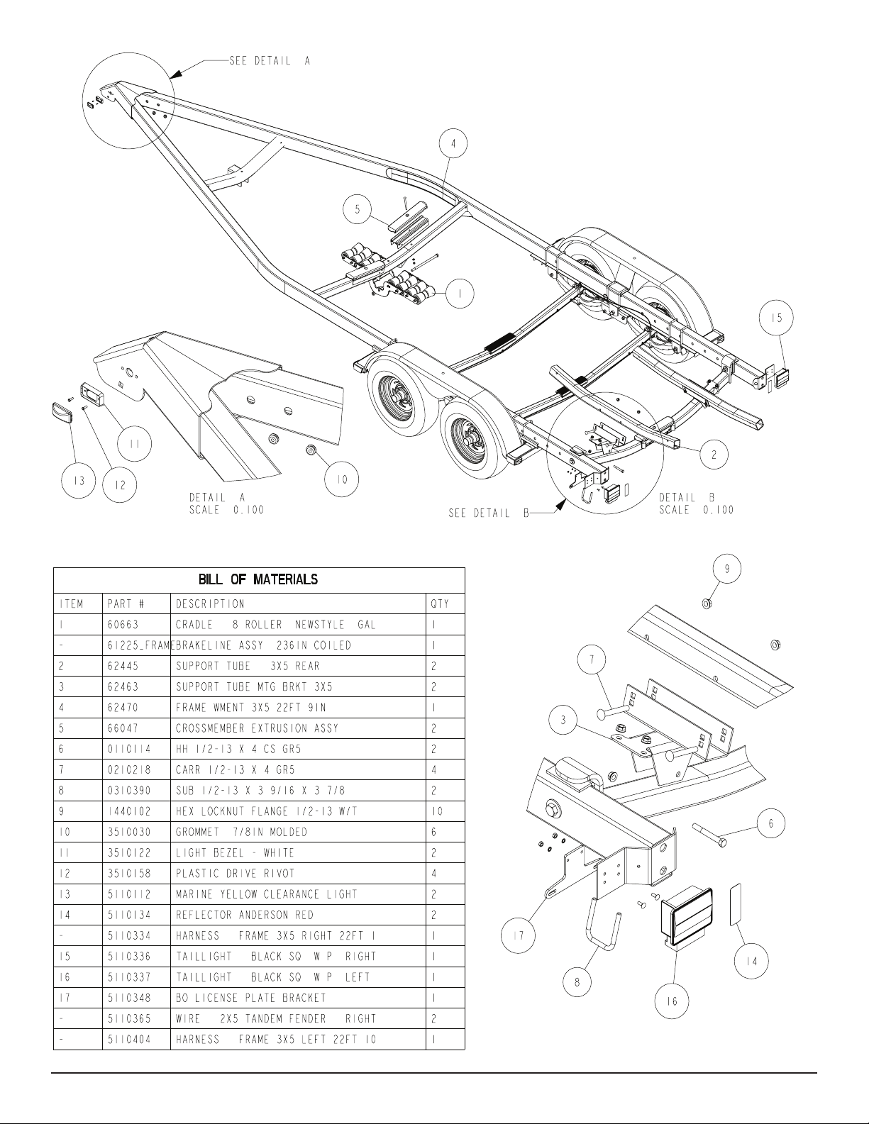
80739__ Frame Bundle - LAV59TCBBL
*ST225/75R15D Carl Tire/Galv or Chrome Rim
3310053 Jack Mounting Hardware Bag
3310052 Jack 1200 LB Swivel
68140 Brake Kit Tandem
4510658 Actuator - 16000# UFP GDC160
61778__ Bunk Assy 36in With Brakts
69976__ Tongue Weldment 58/68/80 Steel
*Check with your dealer/customer service representative for current tire/rim assembly part
number.
ShoreLand’r offers its product line in painted nishes. When
ordering parts, it is important that you specify the nish or color
you have on your product. The 5-digit number along with a 2-digit
space _ _, note that the parts can be purchased in various nishes.
00..........Galvanized
03..........Black
Midwest Industries, Inc. Ida Grove, IA 51445 800.859.3028 www.shorelandr.com 0004187
03/29/2010
Page 1
LAB80TBB Specications
Capacity 8000 lbs.
GVWR: 9990 lbs.
GAWR: 4995 lbs.
Ship Wt: 1280 lbs.
Frm Size: 3X5 (10 Ga)
Tire Size: ST225/75R15D
Rim Size: 15 X 6 “J”
Brake: Surge Hydraulic
Coupler: Actuator, 16000 lbs. UFP
Suspension: 5 Leaf Slipper Springs
Tongue Size: 3X4X7GAX98-3/4” Tongue
Page 2
FINAL ASSEMBLY INSTRUCTIONS
Remove all banded items and the hardware bag from the frame.
Remove the parts and sort by size.
Midwest Industries, Inc. Ida Grove, IA 51445 800.859.3028 www.shorelandr.com 0004187
03/29/2010
Page 2
Page 3
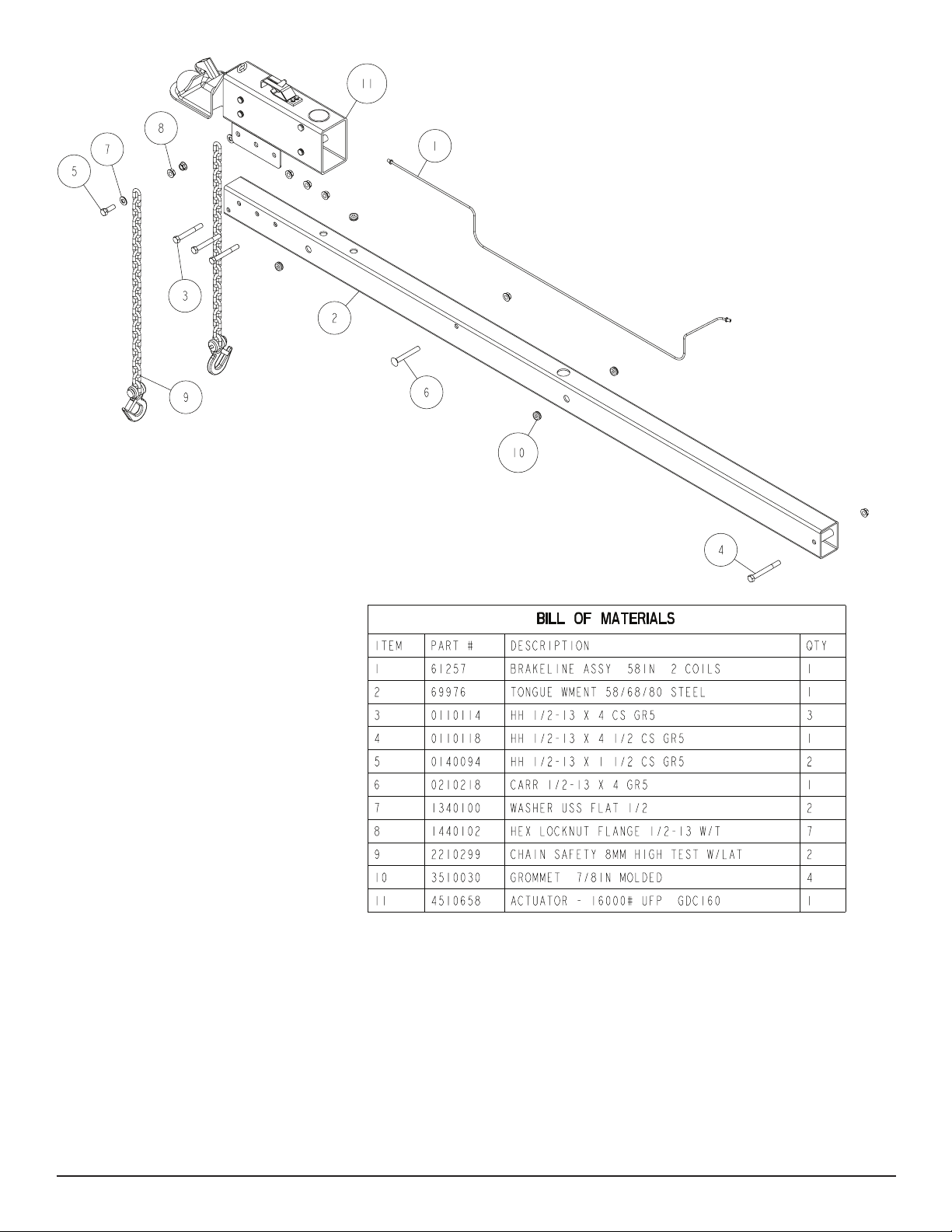
TONGUE
The tongue comes shipped separately. Locate and install under
plug must go to the left side of the trailer and the brown and green
plug must go to the right side of the trailer.
the frames front tongue channel and in the channel welded to the
front cross member which will support the rear of the tongue.
Plug the tongue wire harness ends into the frame harnesses by
matching colors and ends. Place grommets into the wire holes.
Line the hole in the tongue with the hole in the tongue channel. Install the 1/2” x 4-1/2” carriage bolt in the front cross hole and secure
with a 1/2” lock nut. Secure the rear of the tongue to the frame with
Push the extra wire provided either into the hole in the tongue or
else remove the grommet in the side frame and place the extra wire
in the side frame. Replace grommets just removed.
a 1/2” x 4” hex bolt and lock nut. Tighten.
Tongue Wire Harness
Locate the tongue wire harness. Place the end of the wire harness
with the two double plugs into the hole in the top of the tongue. Pull
backwards through the tongue until they can be shed through the
holes in each side of the tongue. Note that the brown and yellow
Brake Line
Remove the brake line from the brake kit box 68140. Locate the 58”
tongue line. Uncoil the line and insert one end into the rear of the
tongue pushing it forward until the end comes out of the front of the
tongue. Locate the brass brake line coupling in the hardware box
and thread on the rear tting of the brake line.
Midwest Industries, Inc. Ida Grove, IA 51445 800.859.3028 www.shorelandr.com 0004187
03/29/2010
Page 3
Page 4
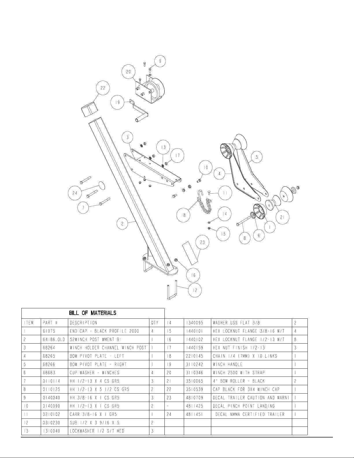
WINCH POST ASSEMBLY
Mount the winch post assembly to the tongue in a location that will
best t your boat. Secure the winch post base weldment (Ref. 2) to
the tongue using (2) 1/2” x 3-9/16’ x 5” U-bolts and hex lock nuts.
Attach the winch post tube weldment to the base just installed with
a 1/2” x 4-1/2” hex bolt and hex lock nut. Tighten only enough to
hold the assembly in position until the boat is positioned on the
trailer.
Midwest Industries, Inc. Ida Grove, IA 51445 800.859.3028 www.shorelandr.com 0004187
03/29/2010
Page 4
Page 5

Actuator
Locate the actuator, and position it on the front of the tongue as
shown. Look into the back end of the actuator and locate the solenoid. Note there is a wire harness coiled around the round solenoid. Uncoil the wire and plug it into the bullet plug on the end of
the blue wire of the tongue harness. Remove the plastic plug from
the port in the rear of the solenoid Thread the tting on the end of
the brake line into the solenoid port from which the plastic plug was
just removed. Tighten.
Align the holes in the actuator with the holes in the tongue. Secure
the actuator to the tongue using three (3) 1/2” x 4” hex bolts and
lock nuts. Tighten.
Bend the line coming out the rear of the tongue in a smooth gradual
radius being careful not to kink the line. Bend so it can be mated
to the brake line from the side frame. Once aligned thread the side
frame brake line into the other end of the coupling. Tighten both
lines into the coupling.
SAFETY CHAINS
Mount the safety chains to the front of the tongue by placing a 1/2”
at washer onto a 1/2” x 5” hex bolt, then insert the bolt through the
last link on one of the safety chains provided. Insert the bolt through
the hole provided in the front of the tongue as shown. Once the bolt
is completely inserted, place on the other safety chain provided.
Place on another 1/2” at washer and secure with a 1/2” hex lock
nut. Tighten.
Diagram C
Midwest Industries, Inc. Ida Grove, IA 51445 800.859.3028 www.shorelandr.com 0004187
03/29/2010
Page 5
Page 6

Midwest Industries, Inc. Ida Grove, IA 51445 800.859.3028 www.shorelandr.com 0004187
03/29/2010
Page 6
Page 7

Midwest Industries, Inc. Ida Grove, IA 51445 800.859.3028 www.shorelandr.com 0004187
03/29/2010
Page 7
Page 8

RB Bunk Assembly
Locate the support arms bundle. Place one of the arms into the
factory installed mounting bracket on the rear pivot with the ends
curved up as shown. Secure in the bracket with two (2) 1/2” x 4”
carriage bolts and hex lock nuts. See Detail B, Page 2. Tighten.
Place one of the bunk assemblies on the end of the support arms
just installed. Line up the top hole in the mounting bracket with the
hole in the support arm and secure with a 1/2” x 4-1/2” hex bolts
and hex lock nuts. Tighten. Repeat on the other end of this support arm. Repeat this complete process on the other support arm.
Note that the bunk assemblies have two height adjustments. The
instructions are to install them in the lowest position to keep the
center of gravity as low as possible for towing. If required, the
bunks can be installed in the raised position for fender cleanrance
by mounting the bunk assemblies to the bunk support arms using
the lower mounting hole.
Midwest Industries, Inc. Ida Grove, IA 51445 800.859.3028 www.shorelandr.com 0004187
03/29/2010
Page 8
Page 9

Rocker Bogie
Locate the rocker bogie as shown on page 4. Note there is a grease
zerk in the center bushing of the rocker bogie. This is necessary so
that it can be serviced in the eld when needed. Position the rocker
bogie into the center mounting channel of the spring bracket. The
rocker must be positioned with the hole locations as shown for
proper operation. Align the center hole of the rocker 60205 with the
hole in the center mounting channel of the spring bracket. Insert a
3/4” x 5-1/2” hex bolt from the outside inward as shown and secure
with a hex lock nut. Tighten. Repeat on the other rocker bogie.
the line so that it can be routed down the back side of the axle
and then over to the brass block on the calipers.
Remove one of the brass plugs from the port in the brass block
on the left brake caliper that best aligns with the routing of the
line. Note also that the bolt holding the brass block to the caliper
can be loosened so that the brass block can be rotated to better
accommodate the angle that the brake line approaches the block
on the caliper. Thread the brake line tting into this port to hold
the line in position making sure that the line does not rub or touch
the spring. Re-tighten the bolt in the brass block if it has been
loosened to rotate the block.
Springs
Position the axles so they are properly aligned with the trailer, which
is the disc brake calipers are on the backside of the axle. Block the
axles so they are approximately 12” above the oor. Drop two 1/2”
x 2-9/16” x 6-1/2” U-bolts down over the axle as shown (See Page
10), then down through the holes in the spring mounting plate that
is welded to the axle. Position a spring so that the eye end of the
spring is to the front of the trailer. Raise the spring up between the
U-bolts, slip on another spring plate and secure with four 1/2” hex
lock nuts. Run the nuts up the threads but do not tighten until after
the springs are mounted into the trailer frame. Repeat on the other
end of this axle, then on the second axle.
Axles
Place the eye of the springs mounted on the rear axle into the rear
of the rocker bogies. Align holes and secure in the rocker bogies
with a 9/16” x 3-3/4” hex bolt and hex lock nut. Raise the rear of the
spring and axle assembly up into the rear spring bracket channel.
Place a spring support channel (Ref. # 6) under the spring. Align
the holes and place 9/16” x 4-3/4” hex bolt through one side of the
spring support channel and one side of the spring bracket channel.
Next place a spring bracket bushing on the top side of the spring,
(See Detail F) align with the bolt just inserted, then insert the bolt
completely through the bushing and the other sides of the spring
bracket channel and the spring support channel. When completely
inserted, secure with a 9/16” hex lock nut. Place the eye of the
springs mounted to the front axle into the front spring bracket channel for the front axle. Secure as above using a 9/16” x 3-3/4” hex
bolt and hex lock nut. Raise the rear of the springs up into the front
side of the rocker bogies. Raise the springs up and secure by placing under the springs 9/16” x 3-3/4” hex bolts and hex lock nuts.
Tighten the bolts just installed.
Tighten all axle U-bolts and spring bolts not tightened at this time.
Tire Size and Carrying Capacity Chart
Tire Size ............................ST225/75R15D
GVWR ...............................9990 LB.
Carrying Capacity ..............8000 LB.
Axle....................................Two Brakes - Standard
Refer to the tire side wall for correct tire pressure.
Brake Line Installation
Open and remove parts from hardware box No. 68140 and sort
all items. Locate the long (90’) brake line and straighten out by
uncoiling on the concrete oor while walking on the line as you
uncoil. The line should be made as straight as possible to assist
in mounting to the axle. Locate ve (5) brake line clamps and
1/4” self tapping screws provided in the kit. Hold the line on the
backside of the axle and familiarize yourself on how it needs to be
formed to connect to the brass blocks on the brake calipers. Form
Route the line down the back side of the axle and secure to the
axle with the ve (5) clamps and self tapping screws. Note that
the axle is pre-drilled for the mounting screws. Route the brake
line over to the brass block on the right brake caliper. Remove
both plugs on the right caliper block. Thread this end of the brake
line into one of the ports on the brass block. Thread the male end
of the 13” brake hose into the other port from which the plug was
removed and tighten. Position the brass block so that neither the
hose nor the brake line will contact or rub the spring. Tighten all
ttings. Place the other end of the hose up through the hole provided in the brake line clip bracket. Secure in place with the hose
clip provided. Item No. 32 on page 6.
Repeat this process on the second axle using the identical component parts in the hardware box. Locate the brass tee in box
68140. Thread the male port of the tee into the female end of the
brake hose of the front axle. Tighten. Remove the plastic cap from
the end of the frame brake line coming out of the side frame by
the axle. Carefully uncoil the brake line enough so that it will reach
the port of the tee just threaded into the brake hose. Thread the
brake line tting into the top port of the tee and tighten.
Locate the 40” long brake line tube in box 68140. Thread one
end of the line into the remaining port of the tee installed in the
previous step. Route the line back to the second axle. Place a coil
in the line to use up the excess line and then connect the other
end of the line into the hose coming from the second axle. Tighten
both ttings. Note that the coil in the line will absorb the vibration
created during towing.
Bleeding the Brake System
Bleed the brake system as specied in the brake manual. The
bleeding process is necessary to remove ALL air entrapped in the
system in order for the brake system to function properly.
http://www.shorelandr.com/pages/o_manual/
AxleBrakeLineServiceBulletin.pdf
All bleeding to the line is to be done through the bleeders on
the calipers.
Fill the actuator reservoir with brake uid and bleed the line
per the instructions in the brake manual.
TIRE & RIM ASSEMBLIES
Mount the tire and wheel assemblies using the 1/2” ne threaded
tapered lug nuts provided. Tighten to 85-95 ft/lb. of torque using the
rotation pattern as shown in the ShoreLandr’s Owners Manual.
Re-torque the lug nuts after 50 miles of driving and then periodically thereafter.
Midwest Industries, Inc. Ida Grove, IA 51445 800.859.3028 www.shorelandr.com 0004187
03/29/2010
Page 9
Page 10

Midwest Industries, Inc. Ida Grove, IA 51445 800.859.3028 www.shorelandr.com 0004187
03/29/2010
Page 10
Page 11

Midwest Industries, Inc. Ida Grove, IA 51445 800.859.3028 www.shorelandr.com 0004187
03/29/2010
Page 11
Page 12

Disc Brake Assembly
Midwest Industries, Inc. Ida Grove, IA 51445 800.859.3028 www.shorelandr.com 0004187
03/29/2010
Page 12
Page 13

Midwest Industries, Inc. Ida Grove, IA 51445 800.859.3028 www.shorelandr.com 0004187
03/29/2010
Page 13
Page 14

Trailer Adjustments
The adjustment of the trailer to your boat is very important not
only for the trailer, but also the boat. Failure to do so may lead to
potential failure or damage to either the trailer or boat.
Adjust as follows:
Once the boat is positioned on the front roller system, the stabilizer pads can be adjusted. This is accomplished by sliding the
pad up against the boat bottom by hand. It is not necessary that
they carry much weight. They are designed to give your boat
added stability while being towed. It may be necessary to adjust
the assembly up so that they can be moved further apart giving
additional support. Pull the assembly away from the boat. Place
Axle Adjustment
The amount of tongue weight on your trailer can be adjusted as
follows:
To lower the tongue weight, adjust the axle assembly forward. To
increase the tongue weight, adjust the axle assembly backward.
The distance that the axle assembly has to be moved will vary
because it is directly related to the weight and center of gravity of
the boat place on it.
Best towing is achieved when the tongue weight is 5-7% of the
total gross load of the complete unit.
To move th e axle assembly, loosen the U-bolts that secure the
assembly to the side frames. Move the assembly to the desired
location, then re-tighten U-bolts.
NOTE: Brake line and wire harness will need care when moving
the assembly.
Rear Support System
Place the boat on the trailer so that the transom is located at the
rear of the support system. On an RB bunk trailer, the transom of
the boat should be within 1-2” of the end of the bunk. The center
of the rear rollers on the roller rack should be approximately
4” from the transom. This gives you maximum support on the
transom. The rear pivot is adjustable forward and backward to
assist in adjusting the trailer to various length boats. This is accomplished by removing the pivot bolt that attaches the rear pivot
to the side frame and then sliding the assembly to the desired
position and re-attaching with the pivot bolt just removed. The
wire harness for the three-light identication light will have to be
rerouted as well.
RB Bunks
Make sure the bunks are positioned far enough apart to give your
the U-bolt that holds the assembly to the cross member in a lower
hole in the bracket. Then push the assembly back against the
boat. Tighten in position.
Winch Post
Now that all other adjustments are complete the winch post can
be adjusted. Slide the winch post base backward on the tongue
until the bow roller comes in contact with the boat. This bow roller
needs to be positioned directly above the boat bow eye to prevent
your boat from moving forward in the event of a sudden stop.
Loosen the three 1/2” hex bolts that clamp the winch holder channel to the winch post. Attach the winch strap into the bow eye and
slide the winch holder channel up or down to the desired position
as you crank the winch tight. Once the bow roller is located just
above the bow eye, tighten the three 1/2” hex bolts that clamp the
winch holder channel to the winch post. Tighten the U-bolts that
secure the winch post assembly to the tongue. Attach the bow
eye safety chain into the bow eye of the boat as well. The chain is
another level of protection to keep your boat and trailer together
as one unit in the event of an accident. It may also be used to
keep your boat on the trailer while loading and unloading at the
ramp,especially with a roller trailer.
Adjustments are now complete. Double check your boat for t. If
desired t has been achieved, tighten all fasteners that may have
either been left loose or have been loosened to do the adjusting.
Re-check all fasteners on the complete trailer to make sure they
are all tight and ready for towing. All fasteners should be periodically check before towing.
The law requires that the white ground wire on both the tongue
wire harness and vehicle harness be properly grounded to respective trailer and vehicle frames.
See your ShoreLand’r Owner’s Guide for further technical infor-
mation regarding your trailer and its components.
boat as much stability as possible while transporting. Position the
bunks so they are located just to the outside of a strake that your
boat may have. This will help center your boat and assist when
loading. The bunks need to be adjusted up high enough to keep
the keel from resting on the center pads. A minimum of one to two
inches of clearance is desirable.
When the desired position is determined, tighten only enough to
hold the bunks from moving while the other adjustments are being
made. Final tightening will be done at the end of the adjusting
process.
Front Support System
RB and Roller
The keel of the boat must rest on the center of the front keel roller
system creating a three-point support system. The keel roller
system is designed to t most boats without needing any further
adjustment.
Midwest Industries, Inc. Ida Grove, IA 51445 800.859.3028 www.shorelandr.com 0004187
03/29/2010
Page 14
Page 15

Midwest Industries, Inc. Ida Grove, IA 51445 800.859.3028 www.shorelandr.com 0004187
03/29/2010
Page 15
 Loading...