

Page 1
®
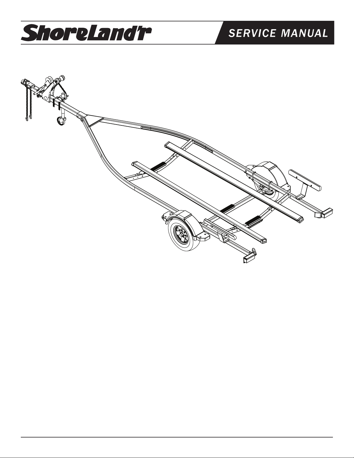
HCV22XL
Harbor Craft 2X3 V22XL
Table of Contents: ...................................................... Page
Frame Drawing & Bill of Materials ................................2-3
Assembly Instructions...................................................3
Swing Tongue ............................................................3
Wire Harness .............................................................3
Safety Chains ............................................................ 3
Winch Post ................................................................3
Jack ...........................................................................3
Trailer Bundles .............................................................4
Tire Size & Carrying Capacity Chart .............................4
Swing Tongue & Safety Chain/Coupler Dwg/BOM ....... 5
Winch Dwg/BOM. .........................................................6
Chassis Drawing & Bill of Materials .............................. 7
Spring Assembly Instructions .......................................7
Axle Assembly Instructions ...........................................7
Tire & Wheel Assembly ................................................7
Axle Dwg/BOM .............................................................8
Poly Bunk Dwg/BOM ....................................................9
Loadguide Dwg/BOM ...................................................10
Poly Bunk/Loadguide Assembly Instructions ................11
Trailer Adjustments ....................................................... 12
Axle Adjustments .......................................................12
Rear Support System ................................................ 12
Front Support System ...............................................12
Winch Post Adjustments............................................12
Safety Instructions .....................................................12
Midwest Industries, Inc. Ida Grove, IA 51445 800.859.3028 www.shorelandr.com 0003715
Page 1 11/10/06
Page 2
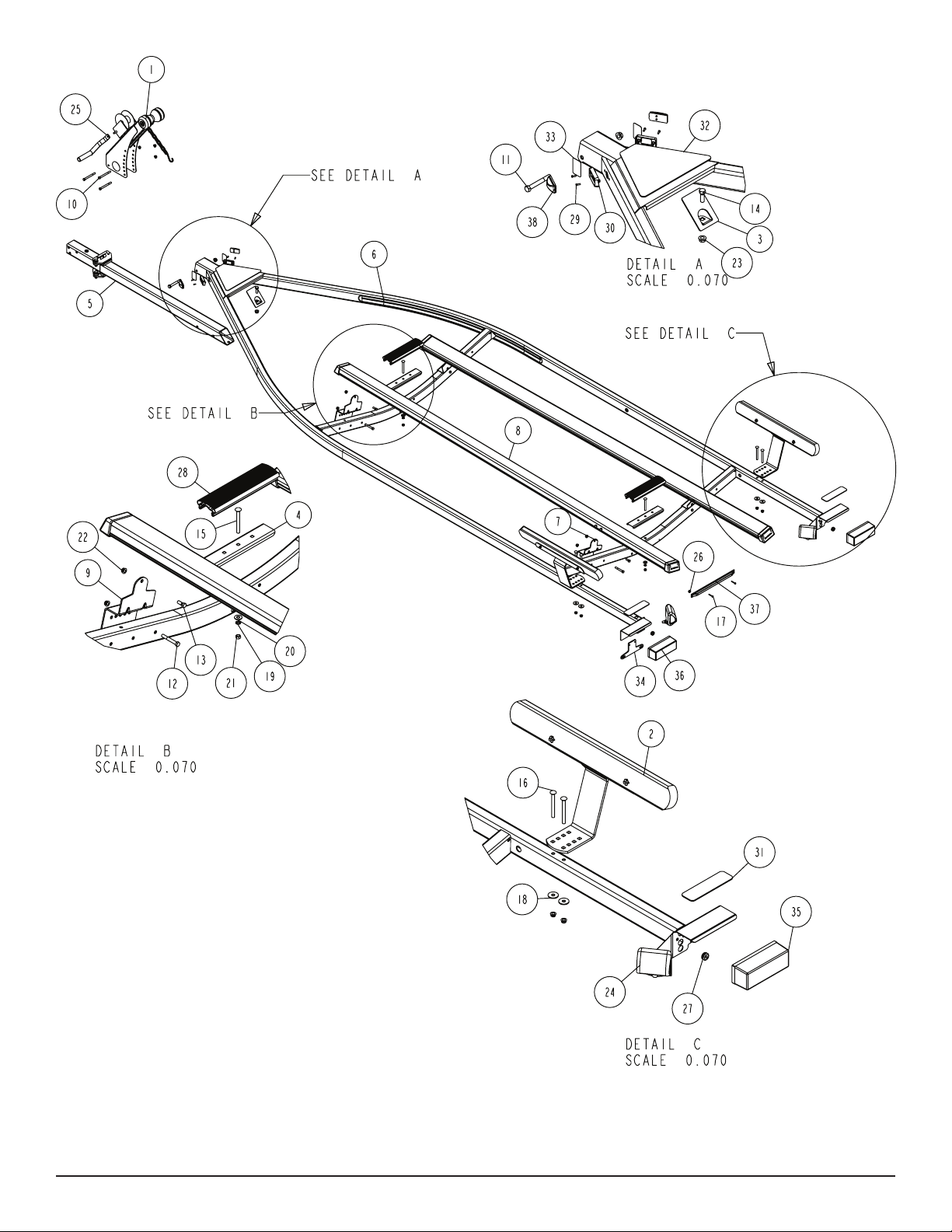
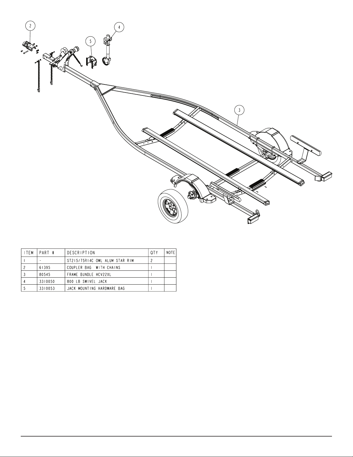
Diagram A
Midwest Industries, Inc. Ida Grove, IA 51445 800.859.3028 www.shorelandr.com 0003715
Page 2 11/10/06
Page 3

(See Detail A) Secure the tongue cover plate in position with a 1/2”
X 1-1/2” hex bolt and 1/2” lock nut. Tighten. Plug the tongue wire
harness ends into the frame harnesses by matching colors and ends.
Push the extra wire into the rear of the tongue or remove the grommets in the side frame and place the extra wire in the side frame.
Replace grommets just removed.
SAFETY CHAINS
Mount the safety chains to the front of the tongue by placing a 3/8”
at washer onto a 3/8” X 1-1/4” hex bolt, then insert the bolt through
the last link of the safety chain. Add another 3/8” at washer. Put
the bolt through the hole on one side of the tongue as shown.
Secure on inside of tongue with a 3/8” hex ange nut. Tighten.
Repeat on the other chain on the other side of the tongue.
WINCH POST
Place the winch assembly on the tongue and secure with three
3/8” X 4” hex bolts and hex flange lock nuts. Place the 3/8”
ange lock nuts on the bolts but do not tighten because they
will have to be readjusted once the boat is on the trailer.
Remove the winch handle nut from the shaft. Align the hole in the
winch handle with the at surfaces on the shaft. Slide in position and
secure with the nut just removed. Tighten.
JACK
It is recommended that the jack be mounted on the right side of the
tongue. This will place it on the opposite side of the winch handle
to eliminate the possibility of the two interfering when being operated.
ASSEMBLY INSTRUCTIONS
Remove all items from the frame. Locate the hardware bag and sort
all items by size.
SWING TONGUE
The tongue comes shipped incorrectly in the frame. Slide the
tongue out from it’s shipping position and reinstall in the front
tongue channel. Line the holes in the tongue with the holes
in the tongue channel. Secure with a 1/2” X 4” hex bolt and
1/2” lock nut in the tongue channel.
Locate the coupler bag. Place the coupler on the end of the
tongue, align holes and secure with one 1/2” X 4” hex bolts and
hex ange lock nuts in the rear coupler hole. Place two 1/2” X
1” hex bolts into the front holes of the coupler and secure to the
inside of the tongue with 1/2” ange lock nuts. Tighten.
WIRE HARNESS
Locate the wire harness. Push the two triangular plugs in the hole
on the top of the tongue, then out the rear of the tongue. Place
the wire harness through the hole in the tongue cover plate.
Remove the hardware bag from the jack and sort all items by size.
Note that the jack mounting plate has only one pair of holes on one
side of the plate while the other side has holes punched to accommodate either 3”, 4”, or 5” tongue.
Place a 3/8” x 4” hex bolt into the single hole of the mounting plate
so the head of the bolt is on the jack side of the plate.
Once inserted, place one of the mounting channels onto the bolt so
the legs of the mounting channel are pointing away from the jack.
Place on a 3/8” lock washer and hex nut. Thread on only far enough
to secure in place.
Repeat the above process on the other single hole of the mounting
plate.
Place the jack on the tongue so that the two bolts just installed are on
the top side of the tongue with the jack on the right side of the tongue
and the mounting channels on the other side of the tongue.
Visually check which of the bottom three holes in the plate will align
just under the bottom side of the tongue. Insert the remaining two
3/8” x 4” hex bolts into these holes and then through the mating
holes in the mounting channel. Secure with 3/8” lock washers and
hex nuts.
Rotate the jack into the up position. Slide the jack forward or backward on the tongue to make sure it will not hit the frame of the trailer
when in the up position.
Tighten all of the mounting bolts to secure the jack assembly to the
tongue.
Always rotate the jack in the up position before towing the trailer.
Midwest Industries, Inc. Ida Grove, IA 51445 800.859.3028 www.shorelandr.com 0003715
Page 3 11/10/06
Page 4
Tire Size and Carrying Capacity Chart
Tire Size ....................... ST185/80R 13-C
GVWR .......................... 2960 lb.
Carrying Capacity ....... 2200 lb.
Axle .............................. Non-Brake
Refer to the tire side wall for correct tire pressure.
Recommended carrying capacity is based on
shipping weight of the trailer with standard
equipment. Adding optional equipment may
decrease the trailer’s carrying capacity.
Midwest Industries, Inc. Ida Grove, IA 51445 800.859.3028 www.shorelandr.com 0003715
Page 4 11/10/06
Page 5

Diagram B
Midwest Industries, Inc. Ida Grove, IA 51445 800.859.3028 www.shorelandr.com 0003715
Page 5 11/10/06
Page 6

Diagram C
Midwest Industries, Inc. Ida Grove, IA 51445 800.859.3028 www.shorelandr.com 0003715
Page 6 11/10/06
Page 7

Diagram D
SPRINGS
Positions the axle so that it is aligned with the trailer.
Place the springs on the top side of the spring pads welded to the
axle. The hook end of the spring must be mounted to the rear of the
trailer. Place a spring clamp on the top center of the spring. Place
the 1/2” X 6-1/2” U-bolts over the top of the spring clamp, spring and
axle. Place the spring and axle U-bolt plate onto the ends of the two
U-bolts. Secure in place with 1/2” lock nuts. Tighten.
AXLE
Place a spring bracket bushing (Ref.#9, Detail E) into the rear of the
spring bracket and secure with a 9/16” x 3-1/4” hex bolt and hex lock nut.
Repeat in the other spring bracket. Position the axle under the frame,
hook the hook loop of the spring around the bushings just installed.
Note: If the axle is positioned too low, the hooks will not hook around the
bushings.
Raise the front of the springs up so they align with the front hole of
the spring bracket. Secure in place with 9/16” X 3-1/4” hex bolts and
lock nuts. Tighten all axle U-bolts and spring bolts.
TIRE & WHEEL ASSEMBLY
Mount the tire and wheel assemblies using the 1/2” ne threaded tapered lug nuts provided. Tighten to 85-95 ft./lb. of torque using the rotation pattern as shown in the ShoreLandr’s Owners Manual.
Re-to rqu e the lug nuts aft er 50 miles of drivin g and then
periodically thereafter.
Midwest Industries, Inc. Ida Grove, IA 51445 800.859.3028 www.shorelandr.com 0003715
Page 7 11/10/06
Page 8

Midwest Industries, Inc. Ida Grove, IA 51445 800.859.3028 www.shorelandr.com 0003715
Page 8 11/10/06
Page 9

Midwest Industries, Inc. Ida Grove, IA 51445 800.859.3028 www.shorelandr.com 0003715
Page 9 11/10/06
Page 10

Midwest Industries, Inc. Ida Grove, IA 51445 800.859.3028 www.shorelandr.com 0003715
Page 10 11/10/06
Page 11

BUNK
The bunk assemblies are completely assembled at the factory and are ready to be installed on your trailer. Note that
the bunk brackets installed in the bunk system are mounted
differently on each end. The one end has the bunk bracket
secured in position by a dart in the aluminum extrusion and
two 3/8” x 3-1/2” hex bolt while on the other end the bunk
bracket is allowed to move up and down the extrusion.
It is recommended that the end of the bunk assembly with
the bunk bracket (Ref.#7, page 2) secured be placed on the
end of the trailer where the transom of the boat will be located when it is on the trailer.
Attach the bunk assembly to the adjustable bunk bracket
using the 3/8” x 1” hex bolt provided. Secure in place with a
3/8” ange lock nut.
Align the other end of the bunk assembly over the adjustable
bunk bracket (Ref.#9, page 2) on the crossemember. Move
the bracket until it is positioned next to the adjustable bunk
bracket. Attach this bunk bracket to the adjustable bunk
bracket using another 3/8” x 1” hex bolt and secure in place
with a 3/8” ange lock nut.
LOADGUIDE
Place loadguide assemebly on the side frame in a location
that best ts your watercraft.
Secure with 3/8” X 4” carriage bolts, special washers and
3/8” ange lock nuts.
Refer to page 2 for placement.
Once both ends of the new bunk assembly are secured to
the adjustable bunk brackets, tighten the bolts just installed
but do not over tighten. The bunk assemblies must be allowed to rotate so they will conform to the boat bottom.
Repeat this process on the other bunk assembly.
Midwest Industries, Inc. Ida Grove, IA 51445 800.859.3028 www.shorelandr.com 0003715
Page 11 11/10/06
Page 12

Refer to your ShoreLand’r Owner’s
Guide and other decals on trailer for
additional information.
SAFETY INSTRUCTIONS
4810709
Proper tongue weight must be maintained.
Rev C 8/28/06
Before towing, check the following to ensure
that:
1. All parts, bolts, nuts and wheel lug
nuts are tight.
2. All wheel lug nuts must be tightened
to a minimum torque rating of 85 ft/lb.
3. Lug nuts must be re-torqued after the
first 50 miles, then periodically there
after.
4. Tires are inflated to manufacturer’s
standards. (See tire sidewall)
5. Wheel bearings have adequate
grease.
6. Hitch ball is the proper diameter and
has a rating equal to or greater than
the GVWR of the trailer.
7. Coupler is properly attached and
secured to coupler ball.
8. Trailer safety chains are crossed
under the tongue and attached to
towing vehicle.
9. All lights are operational. Note: It is
recommended that the trailer lights
be disconnected before backing into
the water.
10. Tie downs, winch strap and bow eye safety chain are secure.
11. Trailer tongue jack is in up or travel
position.
TRAILER ADJUSTMENTS
Axle Adjustment
The amount of tongue weight on your trailer can be adjusted as
follows: To lower the tongue weight, adjust the axle assembly
forward. To increase the tongue weight, adjust the axle assembly
backward. The distance that the axle assembly has to be moved will
vary because it is directly related to the weight and center of gravity
of the boat placed on it. Best towing is achieved when the tongue
weight is 5-7% of the total gross load of the complete unit.
NOTE: The wire harness will need care when moving the
assembly.
Rear Support System
Place the boat on the trailer so that the transom is located
at the end of the bun k. Th e center of the rea r rollers on
th e rol ler rack should be app roxi mate ly 4” from the tra nsom. This gives you maximum support on the transom.
The bunks must be positioned far enough apart to give your boat
as much stability as possible while transporting. Position the bunks
so they are located just to the outside of the boat’s strake. This will
help center your boat and assist when loading.
FRONT SUPPORT SYSTEM
Bunk
The front bunks should be adjusted either in or out so that the bunk
will continue to run just to the outside of the strake of the boat. Adjust
the bunks up so that there is approximately 1” clearance between
the keel of the boat and the center cross member pad.
Winch Post Adjustment
Slide the winch post assembly back towards the boat. The bow stop
roller needs to be located directly above the boat bow eye to prevent
your boat from moving froward in the event of a sudden stop.
Not e t hat t h e ou t e r wi n c h ba s e has s e ver a l hol e s of
adjustment. Changing the bolt location will change the angle of the
winch post and will raise or lower the height of the bow roller. Choose
the bolt location which best matches it to the bow eye height.
Th e in n er and oute r wi n ch post cha n n els can tel e s cope
eithe r in or out wit h respect to each other to lengthen or
shorten the overall length of the post. Loosen the two bolts
located on the back, inside of the channels. Attach the winch
strap int o the bow eye and cra nk th e winch stra p in unt il
the bow eye is located in it’s proper position just above the
bow eye. Slide the inner post in or out to a desired length.
Once the bow stop roller is located in it’s proper position above the bow
eye, tighten the bolts that secure the assembly to the tongue.
Attach the bow eye safety chain into the bow eye as well.
This is anot her level of protection to keep your trailer and
bo a t to gethe r as on e unit. It may be us e d to keep your
boat on the trailer while loading and unloading at the ramp,
especially with a roller trailer.
Adjustments are now complete. Double check your boat
for t. If desired t has been achieved, tighten all fasteners th at may hav e either been left loose or have been
loosened to do the adjusting.
Se e y o u r S h o r e L a n d ’ r O w n e r ’ s G u i d e f or f u r t he r
technical in fo r mation re g a r d i n g y o u r trai l e r and its
components.
Midwest Industries, Inc. Ida Grove, IA 51445 800.859.3028 www.shorelandr.com 0003715
Page 12 11/10/06
 Loading...