

Page 1
®
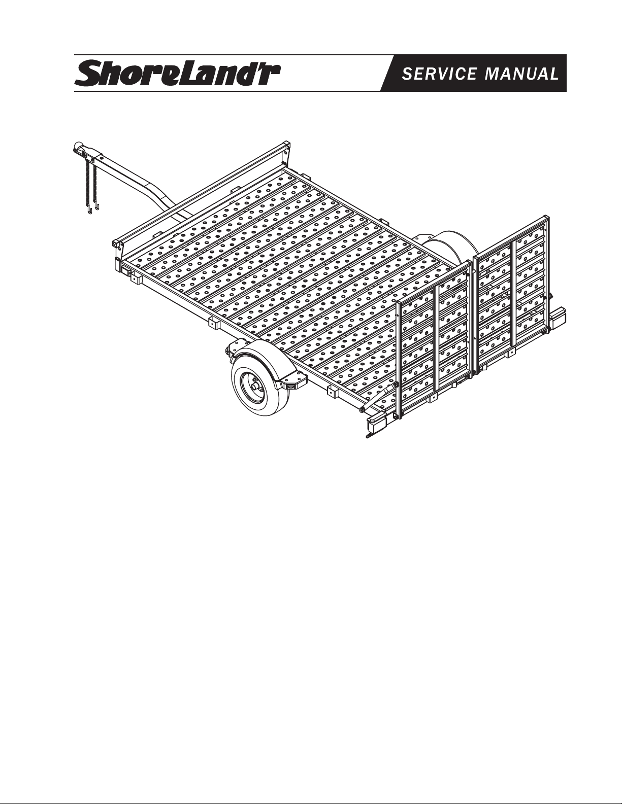
BK2200US-R & BK2200US-R-13
Bundles Required
BK2200US-R Utility Trailer W/Ramp & Front Stop
2 4300182 20.5 X 8 X 10-E Tire/MSilver Rim
1 65069 Literature Packet - Utility
1 6788803 Frame Bundle - 2200US
2 4811433 Decal - ShoreLand’r Utility
Tire Size & Carrying
Capacity Chart
Tire Load Carrying
Size Range Capacity
20.5 X 8 X 10 E 1535 lbs. per/tire
ST185/80R13 C 1480 lbs. per/tire
Refer to the tire side wall for the correct tire
pressure.
BK2200US-R shown
BK2200US-R-13 Utility Trailer W/Ramp & Front Stop
2 4300218 ST185/80R13-C Tire/MSilver Rim
1 65069 Literature Packet - Utility
1 6791903 Frame Bundle - 2200US-R-13
2 4811433 Decal - ShoreLand’r Utility
Tongue Weight Adjustment
Approximate Tongue Weight for Best Towing.
NOTE: Axle is NOT adjustable.
Shift load to obtain proper tongue weight.
Tongue weight should be 5-7% of total gross
weight of trailer and load combined.
Midwest Industries, Inc. Ida Grove, IA 51445 (800)859-3028 www.shorelandr.com 0003187
Page 1 of 6
Page 2
BK2200US-R
Tools Required for Assembly
9/16” Wrench / Socket 7/8” Wrench / Socket
13/16” Wrench / Socket 3/4” Wrench / Socket
5/16” Socket
Assembly Instructions
Safety Chain:
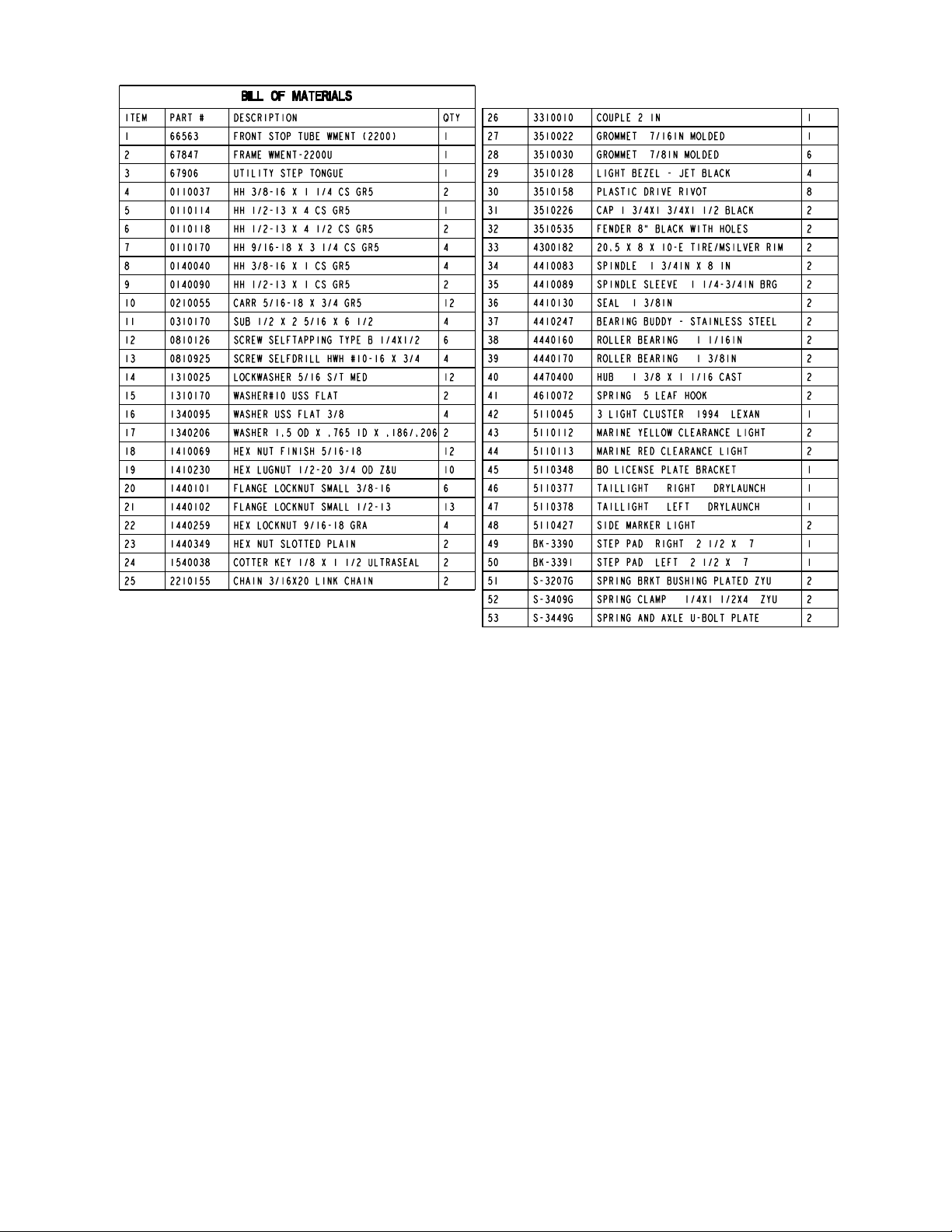
Insert 3/8” X 1-1/4” hex bolt (REF.#4) with 3/8” flat washer
(REF.#16) and safety chain (REF.#25) through the lower hole
on front of tongue. Secure with 3/8” flat washer and 3/8” flange
lock nut (REF.#20) Repeat procedure on opposite side of
tongue.
Coupler:
Mount coupler (REF.#26) to tongue using two (2) 1/2” X 1”
hex bolt (REF.#9) to front holes and one (1) 1/2” X 4” hex bolt
(REF.#5) in rear hole of coupler. Secure with 1/2” flange lock
nuts. (REF.#21).
Axle/Springs:
Mount leaf spring (REF.#41) to axle assembly using two (2)
1/2” X 5/16” X 5-3/4” square u-bolts (REF.#11) over the spring
clamp (REF.#52) and spring. Secure this spring to the axle
assembly using a spring plate (REF.#53) and four (4) 1/2”
flange lock nuts (REF.#21).
Install spring bracket bushing (REF.#51) and 9/16” X 3-1/4”
hex bolt (REF.#7) into rear frame spring shackle. Secure with
9/16” hex nut (REF.#22). Hook leaf spring (REF.#41) on axle
assembly over bushing just installed. Insert 9/16” X 3-1/4”
hex bolt in eye of leaf spring and secure into front frame spring
shackle. Tighten all four bolts on both sides on of trailer to
secure the axle assembly to the under carriage of the trailer.
Tires:
Remove stud thread protectors. Mount tires (REF.#33) to hubs
(REF.#40) using 1/2” lug nuts (REF.#19).
Caution:
1. To prevent damage to your utility trailer or
towing vehicle, tighten all fasteners before
towing.
2. Your utility trailer is equipped with a totally
grounded wire harness. You must be sure
the wire harness plug that comes from the
tow vehicle is grounded to the tow vehicle
using the white grounding wire.
3. Always secure (tie) your load down before
towing.
Midwest Industries, Inc. Ida Grove, IA 51445 (800)859-3028 www.shorelandr.com 0003187
Page 2 of 6
Page 3

BK2200US-R
Midwest Industries, Inc. Ida Grove, IA 51445 (800)859-3028 www.shorelandr.com 0003187
Page 3 of 6
Page 4

BK2200US-R-13
Midwest Industries, Inc. Ida Grove, IA 51445 (800)859-3028 www.shorelandr.com 0003187
Page 4 of 6
Page 5

BK2200US-R-13
Midwest Industries, Inc. Ida Grove, IA 51445 (800)859-3028 www.shorelandr.com 0003187
Page 5 of 6
Page 6

SSBK1172
Rear Ramp Kit for the BK2200U
Assembly Instructions:
Mount the rear ramp weldments (Ref.#3) to the rear of your
BK2200U trailer frame using two (2) 9/16” X 3-1/4” hex bolts
(Ref.#6). Secure with two (2) 9/16” hex lock nuts (Ref.#10).
Refer to the parts drawing on page three (3) for placement.
Secure the rear ramp weldments to the center weldments on
the frame using the pin (Ref.#4) provided. Secure with 3/16”
X 1” cotter keys (Ref.#11).
Mount the gate straps (Ref.#2) to the BK2200U trailer frame
using a 3/16” X 1-1/4” lynch pin (Ref.#13).
Insert the ramp pin (Ref.#12) into the side of the rear ramp
weldments and secure with 1/2” lock washers (Ref.#7) and
1/2” hex nuts (Ref.#9). Secure the gate straps to the ramp
pins just installed (with the ramp weldments an upright position) using 3/16” X 1-1/4” lynch pins.
The rear ramp weldments can be used as single ramps (left
and right) or used a full ramp. Using the full ramp option,
insert the utility ramp bushing (Ref.#1) between the two (2)
ramps (refer to parts drawing on page three (3).) Secure the
bushing with one (1) 1/2” X 4-1/2” hex bolt (Ref.#5) and 1/2”
flange lock nut (Ref.#8).
Tighten all fasteners before using or towing.
Midwest Industries, Inc. Ida Grove, IA 51445 (800)859-3028 www.shorelandr.com 0003187
Page 1 of 4
 Loading...