

Page 1
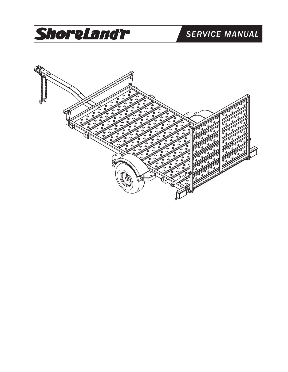
®
BK1400US-R & BK1400US-R-13
Bundles Required
BK1400US-R Utility Trailer w/Ramp & Front Stop
2 4300180 18.5 X 8.5 8-CTire/MSilver Rim
1 65069 Literature Bag - ShoreLand’r Utility
1 6733603 Frame Bundle - 1400US-R
2 4811433 ShoreLand’r Utility Decal - 1400U
Tongue Weight Adjustment
Approximate Tongue Weights for Best Towing. To achieve
the proper tongue weight, shift the load forwards or move
back on the trailer. The tongue weight should be 5% to 7% of
the total gross weight of the trailer and boat combined.
BK1400US-R-13 Utility Trailer W/Ramp & Front Stop
2 4300210 ST155/80R13-CTire/MSilver Dir Rim
1 65069 Literature Bag - ShoreLand’r Utility
1 6743503 Frame Bundle - 1400US-R-13
2 4811433 ShoreLand’r Utility Decal - 1400U
Tire Size & Carrying Capacity Chart
Tire Load Carrying
Size Range Capacity
18.5 X 8.5 X 8 C 940 lbs. per tire
ST155/80R13 C 1100 lbs. per tire
Refer to tire side wall for correct tire pressure.
Caution:
1. To prevent damage to your utility trailer or towing vehicle,
tighten all fasteners before towing.
2. Your utility trailer is equipped with a totally grounded wire
harness. You must be sure the wire harness plug that comes
from the tow vehicle is grounded to the tow vehicle using the
white grounding wire.
3. Always secure (tie) your load down before towing.
Midwest Industries, Inc. Ida Grove, IA 51445 800.859.3028 www.shorelandr.com 0003190
Page 1 of 4 REV A
Tools Required for Assembly
9/16” Wrench / Socket
13/16” Wrench / Socket
7/8” Wrench / Socket
3/4” Wrench / Socket
8/22/03
Page 2
Assembly Instruction
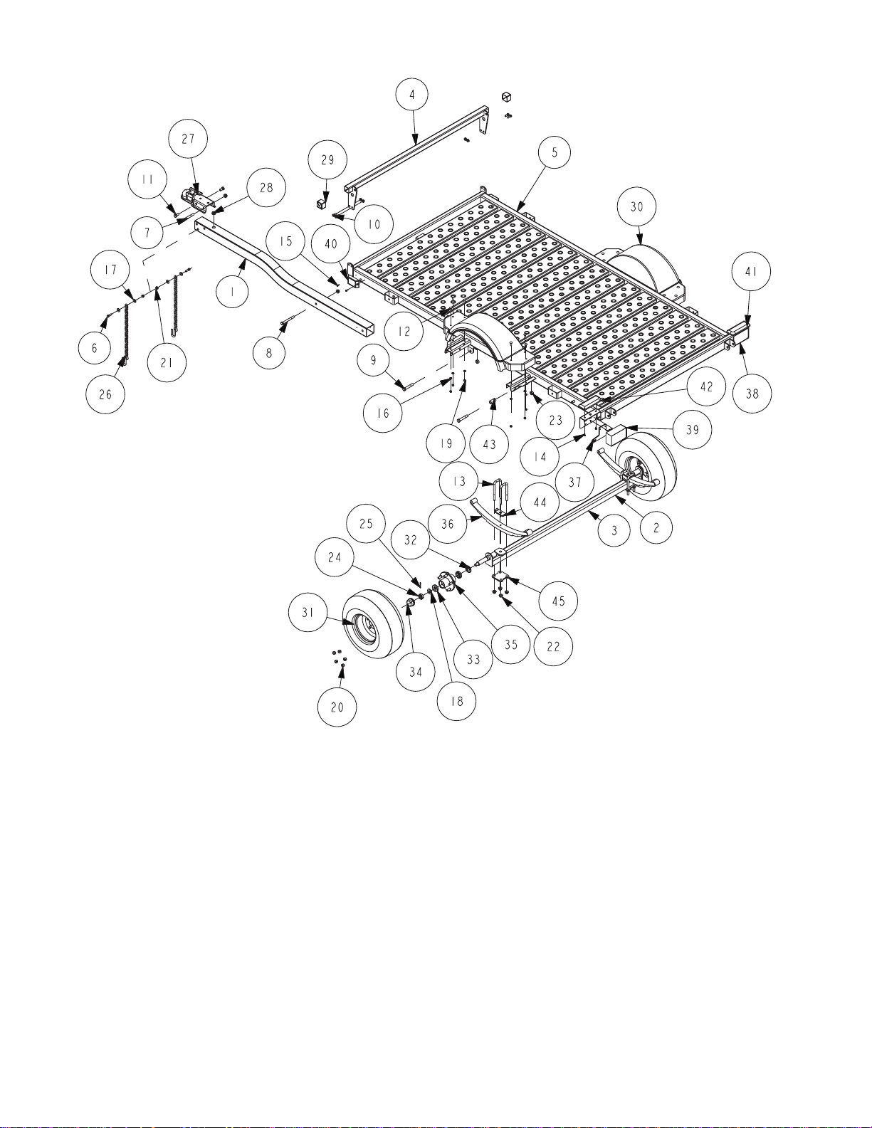
Safety Chain
Insert a 3/8” X 1-1/4” hex bolt (Ref.#5) with 3/8” flat washer
(Ref.#16) and safety chain (Ref.#25) through the lower hole
on the front of the tongue. Secure with a 3/8” flat washer and
3/8” flange lock nut (Ref.#20). Repeat this procedure on the
opposite side of the tongue.
Coupler
Mount the coupler (Ref.#26) to the tongue using two (2) 1/2”
X 1” hex bolts (Ref.#10) to the front holes and one (1) 1/2” X
4” hex bolt (Ref.#6) in the rear hole of coupler. Secure with 1/
2” flange lock nuts (Ref.#21).
Axles/Springs
Mount the spring (Ref.#35) to the axle assembly using two
(2) 1/2” X 2-5/16” X 5-3/4” square u-bolts (Ref.#12) over the
spring clamp (Ref.#44) and spring. Secure this spring to the
axle assembly using a spring plate (Ref.#45) and four (4) 1/
2” flange lock nuts (Ref.#21).
Install the spring bracket bushings (Ref.#43) and 9/16” X 31/4” hex bolts (Ref.#8) into the rear frame spring shackle.
Secure with 9/16” hex nuts (Ref.#22). Hook the leaf spring
(Ref.#3) on the axle assembly over the bushing just installed.
Insert a 9/16” X 3-1/4” hex bolt in the eye of the leaf spring
and secure into the front frame spring shackle. Tighten all
four (4) bolts to secure the under carriage to the trailer.
Tires
Remove the stud thread protectors. Mount the tires (Ref.#30)
to the hubs (Ref.#34) using 1/2” lug nuts (Ref.#19).
OPTIONAL ACCESSORIES:
SS1135 1400U BRAKE KIT (12” or 10” TIRE ONLY)
SSBK1136 FRONT STOP KIT
SSBK1137 RAMP KIT
SS1159 3-SIDE RAIL KIT
SS1160 4-SIDE RAIL KIT
SSBK1183 FRONT SHIELD
SSBK1184
MOTORCYCLE FRONT WHEEL CHOCK KIT
Midwest Industries, Inc. Ida Grove, IA 51445 800.859.3028 www.shorelandr.com
Page 2 of 4 REV A
0003190
8/22/03
Page 3
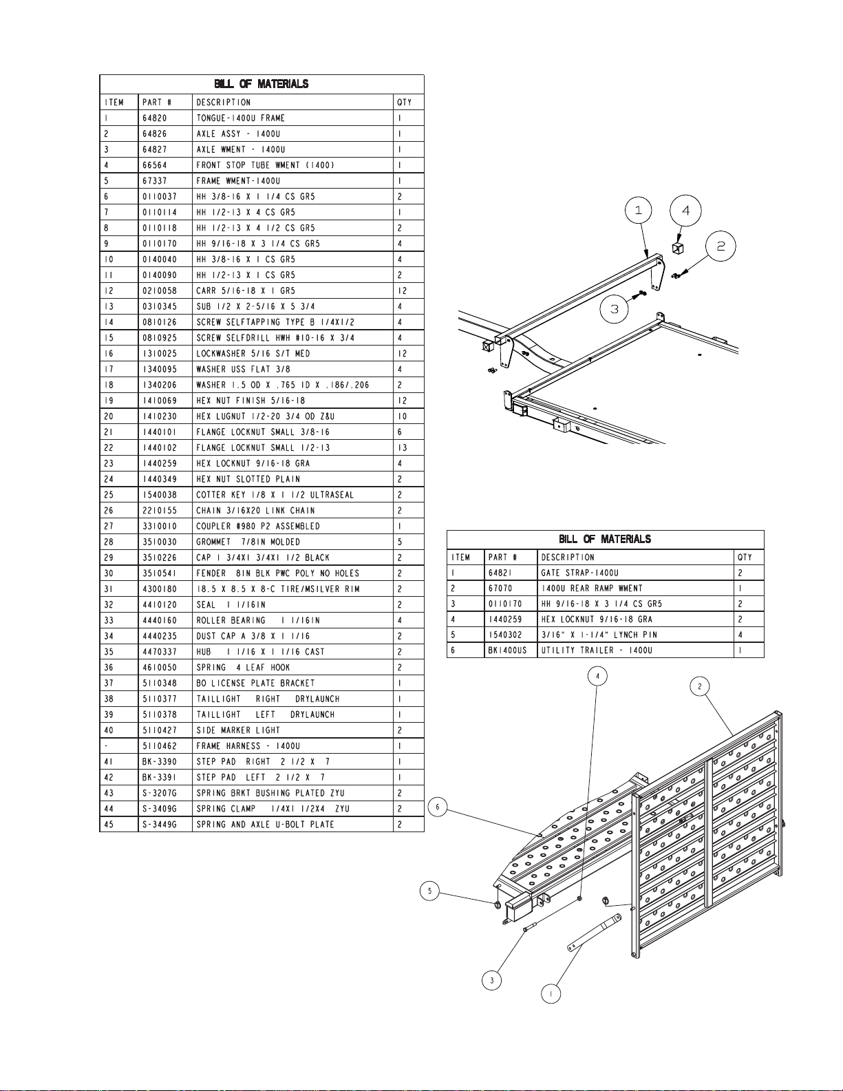
SSBK1136
Front Stop Kit
REF# PART# DESCRIPTION QTY
1 6656403 FRONT STOP TUBE WMENT (1400) ....... 1
2 0140040 HH 3/8-16 X 1 CS GR5 ............................. 4
3 1440101 FLANGE LOCKNUT SMALL 3/8-16 .......... 4
4 3510226 CAP 1 3/4X1 3/4X1 1/2 BLACK ................. 2
DECALS:
4811432 SAFETY DECAL - 1400U ...................... 1
4811433 SHORELAND’R UTILITY DECAL.......... 2
4811434 PINCH POINT DECAL........................... 2
SSBK1137
Ramp Kit
Midwest Industries, Inc. Ida Grove, IA 51445 800.859.3028 www.shorelandr.com 0003190
Page 3 of 4 REV A
8/22/03
Page 4
SS1159
3-Side Rail Kit
SS1160
4-Side Rail Kit
REF# PART# DESCRIPTION QTY
1 6524003 SIDE RAIL - UTILITY ................................. 2
2 6523903 FRONT RAIL - UTILITY ............................. 1
30110059 3/8” X 3-3/4” HEX BOLT ............................ 8
4 1310163 1.377 OD X .390 ID X .105 WASHER ....... 8
5 0140022 5/16” X 3/4” HEX BOLT ............................. 8
6 1310025 S/T MED LOCK WASHER ......................... 8
7 1410069 5/16” HEX FINISH NUT ............................. 8
8 1310005 3/8” INTERNAL TOOTH LOCK WASHER . 8
9 1410109 3/8” HEX FINISH NUT ............................... 8
10 6524103 CORNER BRACE - UTILITY ..................... 2
REF# PART# DESCRIPTION QTY
1 6524003 SIDE RAIL - UTILITY ................................. 2
2 6523903 FRONT RAIL - UTILITY ............................. 1
30110059 3/8” X 3-3/4” HEX BOLT ............................ 8
4 1310163 1.377 OD X .390 ID X .105 WASHER ....... 8
5 0140022 5/16” X 3/4” HEX BOLT ............................. 12
6 1310025 S/T MED LOCK WASHER ......................... 12
7 1410069 5/16” HEX FINISH NUT ............................. 12
8 1310005 3/8” INTERNAL TOOTH LOCK WASHER . 8
9 1410109 3/8” HEX FINISH NUT ............................... 8
10 6524103 CORNER BRACE - UTILITY ..................... 2
11 6524303 TAILGATE CHANNEL - UTILITY ............... 2
12 6524203 UTILITY - TAILGATE ................................. 1
13 1540303 5/16” SAFETY SNAP PIN .......................... 2
Optional Side Rail
REF# PART# DESCRIPTION QTY
1-- 52-1/4” X 2 X 4 WOOD .............................. 4
2-- 97-1/4” X 2 X 4 WOOD .............................. 4
3-- 14-1/2” X 2 X 4 WOOD .............................. 8
4-- 1/4” X 1-1/2” HH LAG SCREW .................. 8
5-- 3/8” X 3-1/2” CARRIAGE BOLT................. 8
6-- 3/8” FLAT WASHER .................................. 16
7-- 3/8” LOCK WASHER ................................. 16
8-- 3/8” HEX NUT ............................................ 16
For the utility trailer owner’s reference.
This is NOT a kit manufactured by ShoreLand’r.
Midwest Industries, Inc. Ida Grove, IA 51445 800.859.3028 www.shorelandr.com 0003190
Page 4 of 4 REV A
8/22/03
 Loading...