

Page 1
BK1000U
ATV Utility Trailer
Bundles Required
BK1000U ATV Utility Trailer - Black
1 6590203 Deck/Cross Bundle - ATV
1 6590303 Deck/Tongue Bundle - ATV
1 6590403 Axle Bundle - ATV
1 6590503 Chasis Bundle - ATV
1 66036 Tire Bundle - BK1000U
Tire Size &
Carrying Capacity Chart
Tire Load Carrying
Size Range Capacity
16.5X6.5X8 C 795 lbs.p/tire
Refer to tire side wall for correct tire pressure.
Tongue Weight Adjustment
Approximate Tongue Weight for Best Towing.
NOTE: Axle is NOT adjustable. Shift load to obtain
proper tongue weight. Tongue weight should be 57% of total gross weight of trailer and load combined.
Page 2

Material List for the BK1000U
NOTE: ShoreLandr offers their product line in either galvanized or painted finish. When ordering parts it is important that
you specify the finish or color you have on your product. The five digit number along with a two digit space _ _, notes
the parts which can be purchased with various finishes. When ordering these items use the five digit prefix and include
the following two digit suffix for proper finish.
Suffix Finish / Color
00 or G Galvanized
03 or BK Black
REF# PART# DESCRIPTION QTY
1 6569903 CHASIS CROSS MEMBER .................... 2
2 6570003 CHASIS CROSS MEMBER .................... 2
3 6570303 ATV UTILITY AXLE WELDMENT ........... 1
4 6570403 ATV UTILTY FRONT CROSS WMENT .. 1
5 6570903 ATV UTILITY DECK ................................ 2
6 6582710 BOLT BUSHING ...................................... 4
7 6588303 TONGUE WMENT 1000U ....................... 1
8 6666703 ATV UTILITY CROSS ............................. 1
9 0110108 HH 1/2-13 X 3 1/4 CS GR5 ..................... 2
10 0110114 HH 1/2-13 X 4 CS GR5 ........................... 1
11 0110118 HH 1/2-13 X 4 1/2 CS GR5 ..................... 1
12 0110170 HH 9/16-18 X 3 1/4 CS GR5 ................... 2
13 0140040 HH 3/8-16 X 1 CS GR5 ........................... 2
14 0140090 HH 1/2-13 X 1 CS GR5 ........................... 2
15 0210102 CARR 3/8-16 X 1 GR5 ............................ 4
16 0210130 CARR 3/8-16 X 3 3/4 GR5 ...................... 8
17 0220110 CARR 3/8-16 X 1 1/2 FULL THRD GR5 . 4
18 0310060 SUB 3/8-16 X 2 3/16 X 1 3/4 ................... 4
19 1340030 LOCKWASHER 3/8 S/T MED ................. 4
20 1340095 WASHER USS FLAT 3/8 ......................... 4
21 1340206 WASHER 1.5 OD X .765 ID X .186/.206 2
22 1410109 HEX NUT FINISH 3/8-16 ........................ 4
23 1410230 HEX LUGNUT 1/2-20 3/4 OD Z&U ......... 10
24 1440101 FLANGE LOCKNUT SMALL 3/8-16 ........ 23
25 1440102 FLANGE LOCKNUT SMALL 1/2-13 ........ 5
26 1440259 HEX LOCKNUT 9/16-18 GRA ................. 2
27 1440349 HEX NUT SLOTTED PLAIN ................... 2
REF# PART# DESCRIPTION QTY
28 1540038 COTTER KEY 1/8 X 1 1/2 ....................... 2
29 3100010 COUPLER #980 P2 ASSEMBLED .......... 1
30 3110334 1/2 X5 HITCH PIN W/LYNCH ................. 1
31 3510084 NON SKID 8" X 60" ROLL FLAT BLK ..... 2
32 3810097 SPACER .515ID X 11/16OD X 7/16 LG . 4
33 4300193 16.5 X 6.5 X 8-C TIRE/MSILVER RIM .... 2
34 4410275 SEAL ........................................................ 2
35 4440160 ROLLER BEARING 1 1/16IN................ 4
36 4440235 DUST CAP A 3/8 X 1 1/16 ....................... 2
37 4470337 HUB 1 1/16 X 1 1/16 CAST ................... 2
38 4610005 SLIPPER LEAF SPRING ........................ 2
39 4811338 WASHER NYLON-1" IDX3" ODX 0.030 . 2
40 S-2029 SPRING BUSHING SPACER ................. 2
DECAL:
-- 4811433 SHORELANDR UTILITY DECAL ........... 2
-- 4811432 SAFETY DECAL ...................................... 1
-- 4850223 CAUTION DECAL - LOWER .................. 1
-- 4850222 CAUTION TILTING DECAL .................... 1
-- 4850372 CAUT REMV LIGHT BAR DECAL .......... 1
ASSEMBLIES AND/OR OPTIONS:
6570803 AXLE ASSEMBLY - ATV 1000U
6570703 HARDWARE BAG - BK1000U
0160034 PPB0160034 BOLT BAG ATV TRAILER
SS1174 LITE KIT FOR ATV TRAILER
SS1179 ATV STAKE POCKET KIT
Tools Required for Assembly
3/4 Wrench/Socket
3/8 Wrench/Socket
5/16 Socket (Sidelights)
9/16 Wrench/Socket
7/16 Wrench/Socket
Cable/Wire (to run harness/light wires)
7/8 Wrench/Socket
13/16 Wrench/Socket
Page 3
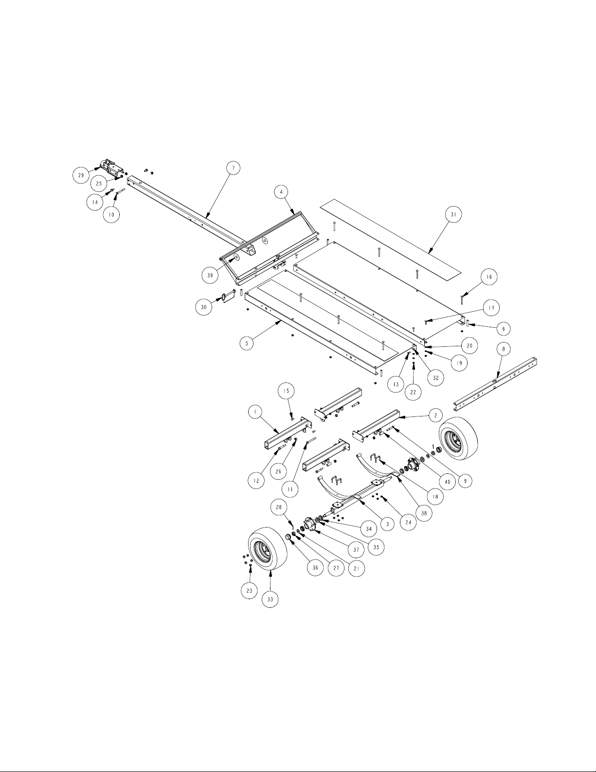
Parts Drawing
NOTE: Optional equipment and replacement
parts must be purchased through an authorized ShoreLandr dealer.
Page 4

BK1000U Assembly Instructions
For easy assembly of your BK1000U
trailer, please follow the directions
given in order. The assembly will be
done with the ATV trailer being
upside down.
Slide the front cross weldment into
the deck as shown.
Use saw horses to aid in the assembly. Remove decks from the boxes.
Lay the decks (with deck side down)
on the saw horses. NOTE: The
decals should face the outside of the
ATV trailer. Decals closest to the front
will determine the front of the trailer.
Mount the front cross weldment to the
front of the deck assembly using a 3/
8 X 3-3/4 carriage bolt (Ref.#16)
through the deck and bolt bushing
(Ref.#7). Secure with a 3/8 flange
lock nut. Repeat on other side.
Remove the hardware bag from the
box - #65904. Sort the hardware.
Using a 3/8 X 1 hex bolt (Ref.#13)
with a 3/8 flat washer (at the head of
the bolt), secure the decks at each
end as shown. Tighten using a 3/8
flange lock nut. Refer to to parts
drawing on page 3 for placement.
Mount the rear cross channel (Ref.#3)
to the rear of the deck assembly
using two (2) 3/8 X 3-3/4 carriage
bolt through the deck and bolt
bushing. Repeat on other side.
Secure the rear channel and the front
cross weldment to the decks in the
middle using a 3/8 X 1-1/2 carriage
bolt with spacer, 3/8 flat washer, 3/8
lock washer and 3/8 hex nut in order
given. Tighten.
Place the chasis crossmember
(Ref.#1) toward the front of the ATV
trailer and the chasis crossmember
(Ref.#2) towards the rear of the ATV
trailer. Repeat other deck as shown.
Refer to parts drawing on page 3 for
proper placement.
Secure the chasis crossmembers to
the outside of the decks using 3/8 X
3-3/4 carriage bolts down through the
deck and chasis crossmember and
tighten with 3/8 flange lock nuts.
Page 5

Secure the chasis crossmembers to
the center of the ATV trailer using 3/8
X 1 carriage bolts and 3/8 flange
lock nuts.
The chasis assembly is shown
complete. Note that the chasis with
the tongue bolt plate are mounted
towards the front of the ATV trailer.
Slide the tongue into the front cross
weldment and secure with 1/2 X 5
hitch pin w/lynch (Ref.#30). In the
rear of the tongue insert a 1/2 X 41/2 hex bolt and two (2) 1/2 nylon
washers (between tongue and
mounting plates). Secure with a 1/2
flange lock nut.
Mount the coupler to the tongue in the
two (2) top holes of the tongue using
one (1) 1/2 X 4 hex bolt in the rear
hole. Secure with a 1/2 flange lock
nut. Secure the front of the coupler to
the tongue using two (2) 1/2 X 1 hex
bolts. Secure with 1/2 flange lock
nuts.
Mount the axle assembly to the
springs just installed using the 3/8 X
2-3/16 X 1-3/4 SUB (Ref.#18) and
secure with 3/8 flange lock nuts.
In the rear chasis cross weldments
insert the spring bushing spacer
(Ref.#40). Secure the bushing to the
chasis cross weldments using 1/2 X
3-1/4 hex bolts and 1/2 flange lock
nuts.
Mount the tires to the axle assembly
using 1/2 lug nuts. Tighten to secure.
Slide the spring into the rear chasis
cross weldment under the spring
bushing just installed. Insert the eye
of the spring in the front chasis cross
weldment and secure with the two (2)
remaining 9/16 X 3-1/4 hex bolts
Tighten with 9/16 hex nuts.
Using a hoist or lifting device, lift
your ATV trailer off the saw horses
and place on its tires.
If installing light kit, install when
trailer is upside down on saw
horses.
Double check all fasteners and
tighten before towing.
The ATV trailer is not highway/
street legal without light kit being
installed. The light kit must be
installed before towing on public
higways and/or streets!
Page 6

SS1181 Light Kit
Run the frame harnesss wires through the
hole on the top side of the tongue when the
trailer is in its normal upright position. Push
the wires to the rear of the tongue and
thread the wires through the wire hole at
the top side of the tongue in its normal
upright position. Place grommets in both
wire holes.
Install molded grommets over wires to
secure in the wires in hole next to the wire
tube.
Slide the wire tube (Ref.#3) into the rear
cross channel and through the chasis. Note
that the two pre-drilled holes on the wire
tube must be inserted in first as shown.
Thread the frame harness wires just
installed in the tongue into the wire tube.
Pull wires out the rear of the tube so that
the plugs are exposed.
Insert the side marker light wires through
the large pre-drilled hole in the side of the
tongue. Pull out the front of the tongue.
Mount the side marker light to the tongue in
the pre-drilled holes using #10-16 X 3/4
self-drill screws (Ref.#9) as shown.
Insert two (2) 1/8 X 1-1/2 cotter key
(Ref.#14) through the pre-drilled holes on
the wire tube (Ref.#3) as shown. Separate
the legs of the cotter key to secure.
Connect wires from the side marker light
to the plugs provided on the frame harness
- brown on brown.
Insert a 3/8 X 1-1/4 hex bolt with a 3/8
flat washer and safety chain through the
lower hole on the front of the tongue.
Secure with a 3/8 flat washer and 3/8
flange lock nut. repeat procedure on
opposite side of the tongue. Loosen and
remove the rear hex nut holding the coupler
to the tongue and place the white ground
wire on the bolt threads. Replace the nut
and tighten.
Place the taillight into the light channel with
the green/brown wiring and white grounding wire fed through the wire hole as
shown.
Notice that the left taillight has the yellow
and brown wire. Slide the taillight into the
light channel. Install the license plate
bracket over the bolts on the taillight. Attach
to the rear crossmember and secure with
the hardware provided with the taillight.
Page 7

When securing the taillight and bracket to
the rear crossmember, secure the
grounding wires before tightening.
Secure the wire tube to the rear
crossmember using a conduit clamp, 1/4 X
3/4 hex bolt and 1/4 flange lock nut.
Tighten 1/4 flange lock nut to secure the
conduit clamp around the wire tube as
shown.
Insert the wire harness through the plastic
tube as shown.
Place a conduit clamp around the plastic
tube.
Pull the wire harness through the plastic
tube as shown.
Secure to the inside of the rear crossmember using a 1/4 X 3/4 hex bolt and 1/
4 flange lock nut.
Plug wire harness in.
AMERICAN STANDARDS FOR WIRING:
YELLOW - RIGHT
GREEN - LEFT
BROWN - RUNNING
WHITE - GROUNDING
Page 8

SS1181 LIGHT KIT
ITEM PART# DESCRIPTION QTY
1 66668 PLASTIC TUBE .845"OD .045WALL .. 2
2 66669 WIRE TUBE FOR ATV ........................ 1
3 6667003 ATV LIGHT CHANNEL ........................ 2
4 0110020 HH 1/4-20 X 3/4 MS ZP ....................... 3
5 0110037 HH 3/8-16 X 1 1/4 CS GR5 ................. 2
6 0810925 SCRW SELFDRILL HWH #10-16X3/4 4
7 1340095 WASHER USS FLAT 3/8 ..................... 4
8 1440097 FLANGE LOCKNUT SMALL 1/4 ......... 3
9 1440101 FLANGE LOCKNUT SMALL 3/8-16 .... 2
10 1540038 COTTER KEY 1/8 X 1 1/2 ................... 2
11 2210142 CHAIN 3/16X20 LINK CHAIN ............. 2
12 2300001 CONDUIT CLAMP EMT 3/4 ................ 1
13 2300002 CONDUIT CLAMP R-12 ...................... 2
14 3510030 GROMMET 7/8IN MOLDED .............. 4
15 5110348 BO LICENSE PLATE BRACKET ........ 1
16 5110377 TAILLIGHT RIGHT DRYLAUNCH .. 1
17 5110378 TAILLIGHT LEFT DRYLAUNCH..... 1
18 5110427 SIDE MARKER LIGHT ........................ 2
- 5110428 WIRE HARNESS - FRAME ................ 1
SS1179
Stake Pocket Kit
Mount the stake pockets onto the pre-drilled holes on the
frame of your ATV trailer using 1/4 X 3/4 hex bolts
(Ref.#6) and secure with 1/4 flange lock nuts (Ref.#12).
ITEM PART# DESCRIPTION ............................. QTY
1 6570503 BOLT-ON STAKE POCKET .......... 8
2 0110020 HH 1/4-20 X 3/4 MS ZP ................16
3 1440097 FLANGE LOCKNUT 1/4 ............... 16
2X4 Wood is recommended
4 pcs @ 74
4 pcs @ 43
8 pcs @ 12
74
12
THESE SIDE RAIL COMPONENTS SHOWN CAN BE
PURCHASED AT YOUR LOCAL LUMBER YARD OR
HARDWARE STORE.
Made in the USA Midwest Industries, Inc. Ida Grove, IA 51445 Tele: 712/364-3365 0002740
43
REV A 9/20/00
 Loading...