

Page 1
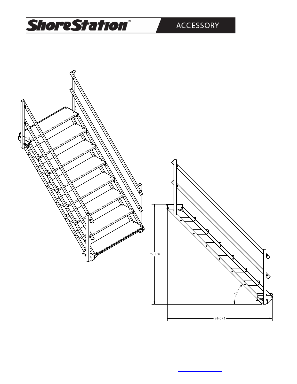
Dock Shore Step - 8 Steps
ADSS-8-15
6919015 Leg Bundle Shore Steps
6919215 Shore Step Frame Bundle (8 Step)
6587315 Hand Rail Bundle (8 Step)
Bundles Required
9/16” Wrench/Socket (Assembly)
Line-up Punch (Assembly)
Level (Installation)
Tape Measure (Installation)
Tools Required
45° Maximum Recommended
Installation Angle
The assembly and installation of the Dock Aqua Step is recommended
to be performed by more than one person.
Midwest Industries, Inc. Ida Grove, IA 51445 800-859-3028 www.shorestation.com 0003518
Page 1 of 7 REV C 03/24/2011
Page 2
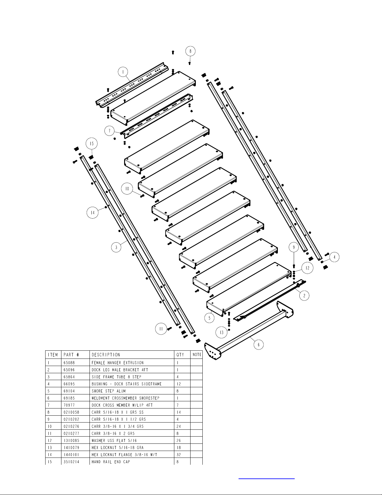
Main Frame Assembly
Midwest Industries, Inc. Ida Grove, IA 51445 800-859-3028 www.shorestation.com 0003518
Page 2 of 7 REV C 03/24/2011
Page 3
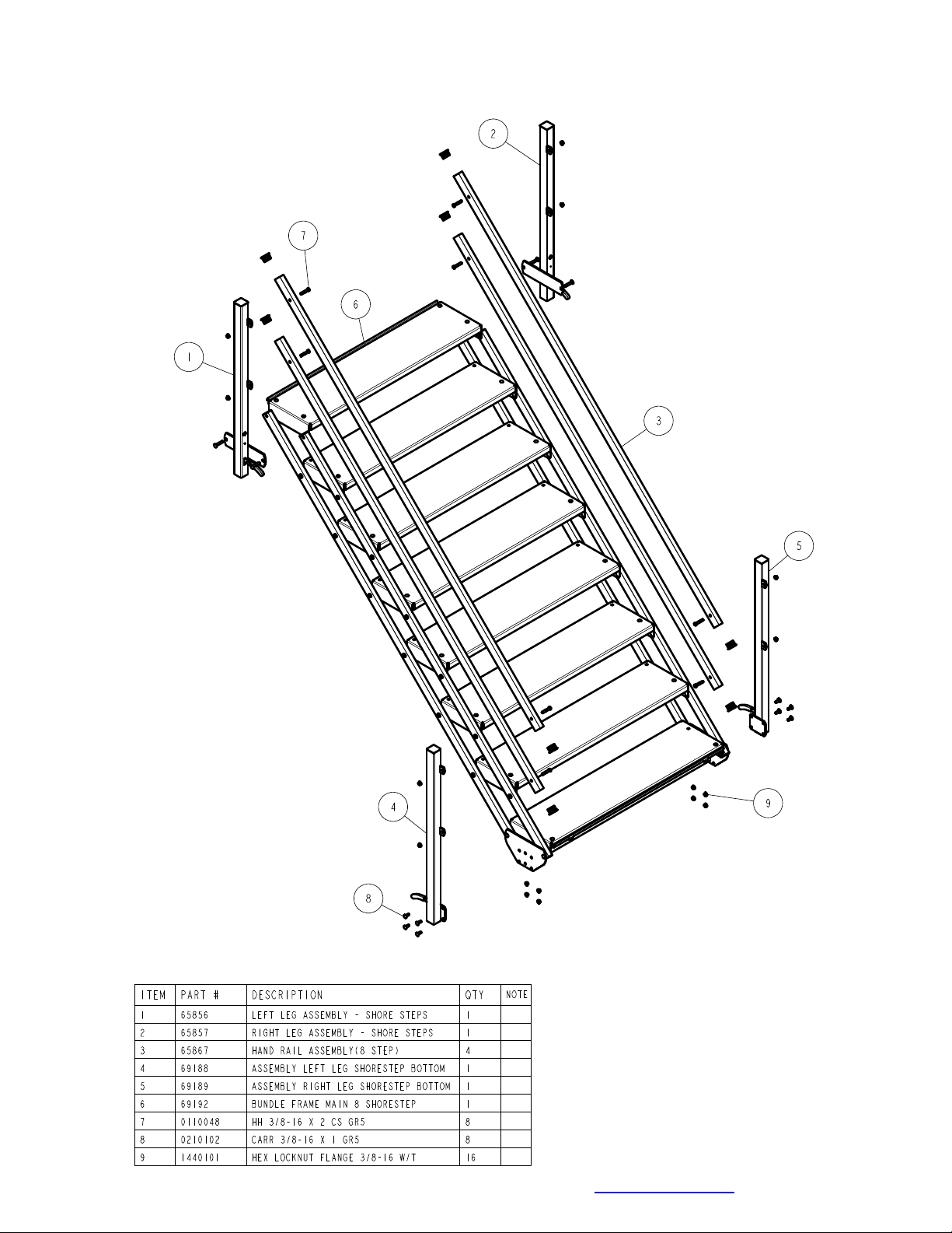
Leg Assemblies & Handrails
Midwest Industries, Inc. Ida Grove, IA 51445 800-859-3028 www.shorestation.com 0003518
Page 3 of 7 REV C 03/24/2011
Page 4

Midwest Industries, Inc. Ida Grove, IA 51445 800-859-3028 www.shorestation.com 0003518
Page 4 of 7 REV C 03/24/2011
Page 5

Midwest Industries, Inc. Ida Grove, IA 51445 800-859-3028 www.shorestation.com 0003518
Page 5 of 7 REV C 03/24/2011
Page 6

ASSEMBLY INSTRUCTIONS
1. Cut the banding on the bundles and sort the parts and hardware by size.
2. Identify the top of the steps by locating the end with the two latch pins. Once located, position the
steps so that they are right side up.
3. Loosen the bolts that hold the steps to the side rails slightly so that they can be rotated.
4. Identify the bottom leg frames. Position the bottom
legframe weldments on the outside of the crossmember
weldments. Insert the bolts through the holes in the
plates of the leg frame weldment, crossmember weldment. With the bolts are in place secure on the inside of
the crossmember weldment with a 3/8” hex flange lock
nut. With the flange lock nut tightened, place an acorn
nut on the exposed threads of bolts. Repeat on other
bolts. Position as shown with leg cam lever pointing
towards the step assembly.
5. Note that the bolts that hold the top step to the side rails are shipped with the nuts on the outside.
These bolts will have to be removed and repositioned the opposite direction when the leg weldments
are installed. Also note that there is a spacer bushing
located inside the side rail to keep the tube from
collapsing when tightening. Caution should be used
when removing the bolts so that this spacer is not
lost or positioned improperly.
7. Identify the top right and left leg frame weldments. Position the leg frames so that the leg cam levers
are pointing towards the step assembly. (See drawings on page 4.) Remove the bolts using the
procedure in Step 5. Secure the right and left leg frames to the side rails with the bolts just removed.
Secure with 3/8” flange lock nuts. With the flange lock nut tightened, place an acorn nut on the exposed
threads of bolts.
Tip: When mounting the upper leg
assemblies, remove only one bolt at a
time. Insert it into the corresponding hole
on the leg assembly, then thru the side
rail assembly with bushing and cap and
then thru the step assembly. Repeat this
process by removing the bolt swing the
leg assembly into position and insert from
the outside in.
Midwest Industries, Inc. Ida Grove, IA 51445 800-859-3028 www.shorestation.com 0003518
Page 6 of 7 REV C 03/24/2011
Page 7

Handrail Assembly Instructions
Locate the handrails. Note that the holes in the
handrails are at different distances from the ends of
the rail. Position the handrails so that the end with
the hole 2-1/2” from the end is attached to the
bottom leg frame weldments. Attach the rails to the
leg frames by placing a 3/8” x 1-3/4” bolt through the
rail, then insert the bolt through the hole provided in
the leg frame. Secure with a 3/8” acorn lock nut.
Repeat this process on the other end of rail and on
other rails
.
Final Installation Instructions
Note that the extension legs are not provided with the dock steps because every application will require
its own length of legs. Legs are available in the following lengths: 10”, 17”, 31”, 49”, & 61”. Purchase the
leg length that best fits your application.
Once the steps are in their permanent location, tighten all nuts and bolts loosened during assembly.
Assembly is complete.
Safety Instructions
Safety Tips for Lifting and Carrying
• Make sure you have help installing this product.
The weight of this unit is 142 lbs.
• Make sure your footing is solid.
• Get close to the load.
• Keep your back straight.
• Center your body over your feet.
• Lift with your legs.
• Move your feet to turn - Don’t twist.
• Use mechanical assistance if it’s available.
• Clear a pathway for carrying.
• Communicate with lifting partners when
lifting/carrying.
• Take small steps when carrying.
• Signal lifting partners when ready to lift and set
down.
• Keep hands clear when folding and unfolding rail
bundle.
• Steps may slippery when wet - Use handrails.
Midwest Industries, Inc. Ida Grove, IA 51445 800-859-3028 www.shorestation.com 0003518
Page 7 of 7 REV C 03/24/2011
 Loading...