

Page 1

®
2 X 5
Bundle Document Reference
How to read your Service Manual:
To identify the model of your trailer please refer to the VIN decal located on the inside of the left side frame at the front of the trailer.
This Bundle Document Reference Sheet refers to the model identification of your trailer and the components that make up that particular
trailer. Refer to the chart below: Listed are the various components with document numbers listed. The document number is located in
the lower right-hand corner of each service manual sheet. When referencing the different components of your trailer, please refer to the
document number and revision entry with date.
When contacting your dealer for service, please refer to the document numbers and revision entry dates.
FRAME SUBASSY CHASSIS WINCH ASSY
DOC# DOC# DOC# DOC#
SLB46TB 0002899 - - - - - - - - 0002905 0002814
SLB46TBB 0002899 - - - - - - - - 0002906 0002814
SLB55TBB 0002900 - - - - - - - - 0002907 0002908
SLR46TB 0002901 0002888 / 0002909 0002905 0002814
SLR46TBB 0002901 0002888 / 0002909 0002906 0002814
SLR55TBB 0002902 0002888 / 0002910 0002907 0002908
SLRB46TB 0002903 0002888 0002905 0002814
SLRB46TBB 0002903 0002888 0002906 0002814
SLRB55TBB 0002904 0002888 0002907 0002908
ROLLER
Color Coating Reference
NOTE: ShoreLandr offers their product line in either galvanized or painted finish. When ordering parts it is important that you specify
the finish or color you have on your product. The five digit number along with a two digit space _ _, notes the parts which can be
purchased with various finishes. When ordering these items use the five digit prefix and include the following two digit suffix for proper
finish.
Suffix Finish / Color
00 or G Galvanized
01 Arctic White
03 or BK Black
06 or AW Antique White
Cautions/Warnings
The law requires that the white ground wire on the both the tongue wire harness and the vehicle harness be properly grounded
to the respective trailer and vehicle frames.
Double check all nuts and bolts tighten before towing.
Tongue Weight Adjustment
Approximate Tongue Weight for Best Towing. Tongue weight too high, move the axle assembly forward. Tongue weight too low,
move the axle assembly backward. Tongue weight should be 5-7% of total gross weight of both boat and trailer combined.
Made in the USA Midwest Industries, Inc. Ida Grove, IA 51445 (800)859-3028 0002898
www.shorelandr.com REV A 10/20/00
Page 2

Page 3
®
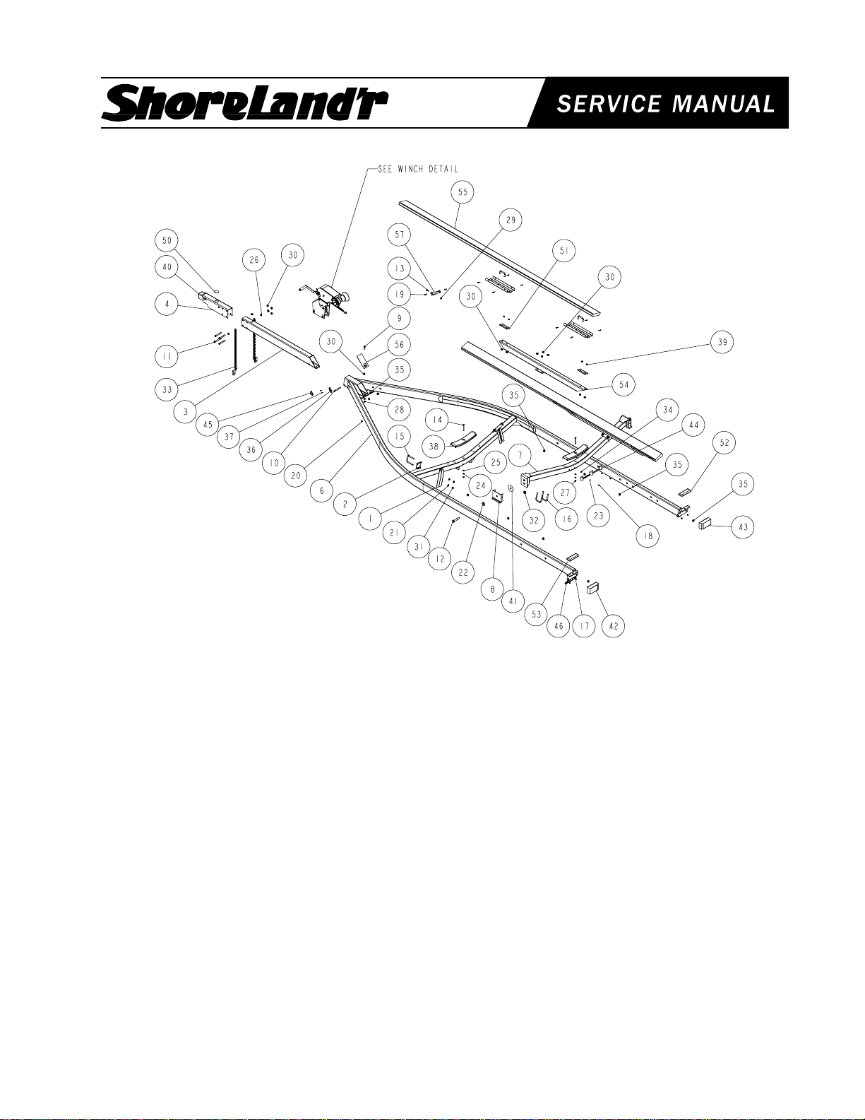
SLB46TB / SLB46TBB
0002814
REF# PART# DESCRIPTION QTY
1 60047-- ADJ BUNK BRKT ....................................... 2
2 6046200 ADJUSTABLE BUNK CLAMP ................... 2
3 65541-- TONGUE 3X5X55 ...................................... 1
4 65542-- OUTER HOUSING - UFP ACTUATOR ..... 1
5 65601 BRAKELINE ASSY 56" ............................. 1
6 66103-- FRAME WMENT 80 WIDE 208 LONG ...... 1
7 66129-- REAR PIVOT WMENT (80 WIDE) ............. 1
8 6654000 REAR PIVOT STOP WMENT (2X5) .......... 2
9 0110096 HH 1/2-20 X 1-1/2 ...................................... 1
10 0110114 HH 1/2-13 X 4 CS GR5 .............................. 4
11 0110120 HH 1/2-13 X 5 CS GR5 .............................. 1
12 0120281 HH 3/4-16 X 4 CS GR5 .............................. 2
13 0140040 HH 3/8-16 X 1 CS GR5 .............................. 2
14 0210130 CARR 3/8-16 X 3 3/4 GR5 ......................... 2
15 0310228 SUB 1/2 X 3 9/16 X 4 1/4 .......................... 2
16 0310390 SUB 1/2 X 5 9/16 X 3 ................................. 4
17 0810126 SCREW SELFTAP TYPE B 1/4X1/2 ......... 4
18 0810925 SCREW SELFDRILL HWH #10-16 X 3/4 .. 2
19 0810930 SCREW SELFTAP #10-12X1 1/4 TYPE A 4
20 0810945 SCREW SELFDRILL 1/4-14X3/4 .............. 1
21 1310040 LOCKWASHER 1/2 S/T MED .................... 4
22 1310120 WASHER USS FLAT 3/4 US ..................... 2
23 1310170 WASHER #10 USS FLAT .......................... 2
24 1340030 LOCKWASHER 3/8 S/T MED .................... 2
25 1340095 WASHER USS FLAT 3/8 ........................... 2
26 1340100 WASHER USS FLAT 1/2 ........................... 3
27 1410109 HEX NUT FINISH 3/8-16 ........................... 2
28 1410209 HEX LOCKNUT 1/2-20 .............................. 1
REF# PART# DESCRIPTION QTY
29 1440101 FLANGE LOCKNUT SMALL 3/8-16 .......... 2
30 1440102 FLANGE LOCKNUT SMALL 1/2-13 .......... 21
31 1440159 HEX NUT FINISH 1/2-13 ........................... 4
32 1440321 HEX LOCKNUT 3/4-16 GRB ..................... 2
33 2220272 CHAIN 8/0 MACH CHAIN 37" W/837 ........ 2
34 3510022 GROMMET 7/16IN MOLDED ................... 1
35 3510030 GROMMET 7/8IN MOLDED ..................... 12
36 3510122 LIGHT BEZEL - WHITE ............................. 2
37 3510158 PLASTIC DRIVE RIVOT ............................ 4
38 3510542 MOLDED REAR CROSSMEMBER PAD .. 2
39 3810097 SPACER .515ID X 11/16OD X 7/16 LG ... 8
40 3991013 ACTUATOR UFP DISC BRAKE AXLE ...... 1
41 4811339 WASHER NYLON - 13/16 ID X 3-3/4 ........ 2
42 5110013 DRY LAUNCH LIGHT ASSY (LEFT) ......... 1
43 5110014 DRY LAUNCH LIGHT ASSY (RIGHT) ....... 1
44 5110045 3 LIGHT CLUSTER 1994 LEXAN ........... 1
45 5110112 MARINE YELLOW CLEARANCE LIGHT .. 2
46 5110348 BO LICENSE PLATE BRACKET ............... 1
47 5110347 HARNESS 5-PRONG FLAT ..................... 1
48 5110402 HARNESS FRAME 2X4 200+ 2X5 RT .... 1
49 5110403 HARNESS FRAME 2X4 200+ 2X5 LT ..... 1
50 7010168 CAP PLASTIC OUTER MEMBER 2IN DI . 1
51 S-3264 BUNK SUPPORT PIVOT 10 GA GALV ... 4
52 S-3390 STEP PAD RIGHT 2 1/2 X 7 .................. 1
53 S-3391 STEP PAD LEFT 2 1/2 X 7 ..................... 1
54 S-3468 3X3 63&1/2 BUNK SUPPORT TUBE ........ 2
55 S-3489 BUNK ASSY SHORT 2X6X12FT ............. 2
Made in the USA Midwest Industries, Inc. Ida Grove, IA 51445 (800)859-3028 0002899
www.shorelandr.com REV A 10/24/00
Page 4

Final Assembly Instructions
Remove the small parts from the frame by cutting the
bands. Remove the bolt bag and sort all nuts and bolts by
size.
Tongue:
Slide the tongue into the frame cap of the frame. Line up
the holes and fasten the tongue in the side of the frame
cap with a 1/2 X 4-1/4 hex bolt and 1/2 flange lock nut.
Fasten the tongue in the rear of the frame cap with a 1/2 X
1-1/2 hex bolt and 1/2 hex lock nut. Plug the tongue
harness into the frame harness, use grommets to secure
the wires in the wire holes.
Actuator & Safety Chain:
Slide the actuator into the actuator housing unit and secure
with two (2) pins and snap rings provided with the actuator.
Secure the actuator-housing unit to the front of the tongue
using three (3) 1/2 X 4 hex bolts and 1/2 flange lock
nuts. Using a 1/2 X 5 hex bolt on the lower right mounting
hole on the tongue, secure the safety chain. Place a 1/2
flat washer on the 1/2 X 5 hex bolt followed by one (1)
safety chain and insert into the actuator housing unit and
the tongue. Place a second safety chain on the bolt
followed by a 1/2 flat washer and 1/2 flange lock nut.
Bunk Assembly:
Pre-assemble the bunks as described prior to installing on
the rear pivot. Lay the carpeted bunks upside down so the
u-bolts under the bunks are facing up. Install the bunk
saddle over the u-bolt so that the curve in the saddle
matches the curve in the 16 bunk bracket. Install the large
bunk support tube over the u-bolts. With the u-bolts
protruding through the support tube, install the 7/16
spacers over the u-bolts. Install 1/2 flat washers and 1/2
hex lock nuts. Tighten. Repeat for the other side. If
properly assembled the bunk will freely pivot when the ubolts are tight.
Fasten the front portion of the bunks to the 2X6 bunk
bracket with 1-1/4 screws.
Page 5
®
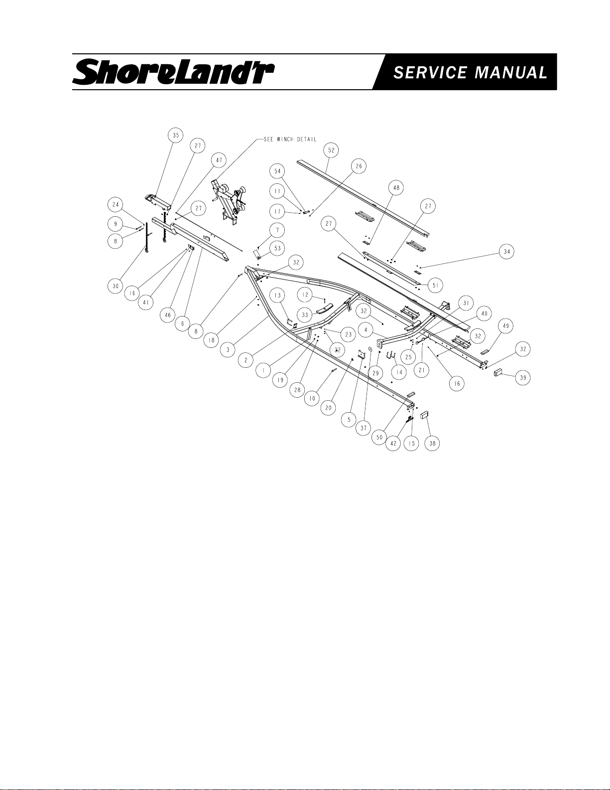
SLB55TBB
0002908
REF# PART# DESCRIPTION QTY
1 60047-- ADJ BUNK BRKT ....................................... 2
2 6046200 ADJUSTABLE BUNK CLAMP ................... 2
3 66104-- FRAME WMENT 80 WIDE 226 LONG ...... 1
4 66129-- REAR PIVOT WMENT (80 WIDE) ............. 1
5 66540-- REAR PIVOT STOP WMENT (2X5) .......... 2
6 66601-- TONGUE WMENT 63 IN FOR DEMCO .... 1
7 0110096 HH 1/2-20 X 1-1/2 ...................................... 1
8 0110114 HH 1/2-13 X 4 CS GR5 .............................. 3
9 0110120 HH 1/2-13 X 5 CS GR5 .............................. 1
10 0120281 HH 3/4-16 X 4 CS GR5 .............................. 2
11 0140040 HH 3/8-16 X 1 CS GR5 .............................. 2
12 0210130 CARR 3/8-16 X 3 3/4 GR5 ......................... 2
13 0310228 SUB 1/2 X 3 9/16 X 4 1/4 .......................... 2
14 0310390 SUB 1/2 X 5 9/16 X 3 ................................. 4
15 0810126 SCREW SELFTAP TYPE B 1/4X1/2 ......... 4
16 0810925 SCREW SELFDRILL HWH #10-16 X 3/4 .. 6
17 0810930 SCREW SELFTAP #10-12X1 1/4 TYPE A 4
18 0810945 SCREW SELFDRILL 1/4-14X3/4 .............. 1
19 1310040 LOCKWASHER 1/2 S/T MED .................... 4
20 1310120 WASHER USS FLAT 3/4 US ..................... 2
21 1310170 WASHER #10 USS FLAT .......................... 2
22 1340030 LOCKWASHER 3/8 S/T MED .................... 2
23 1340095 WASHER USS FLAT 3/8 ........................... 2
24 1340100 WASHER USS FLAT 1/2 ........................... 3
25 1410109 HEX NUT FINISH 3/8-16 ........................... 2
26 1440101 FLANGE LOCKNUT SMALL 3/8-16 .......... 2
27 1440102 FLANGE LOCKNUT SMALL 1/2-13 .......... 21
REF# PART# DESCRIPTION QTY
28 1440159 HEX NUT FINISH 1/2-13 ........................... 4
29 1440321 HEX LOCKNUT 3/4-16 GRB ..................... 2
30 2210180 CHAIN 1/4(7MM)X 10 LINKS .................... 2
31 3510022 GROMMET 7/16IN MOLDED ................... 1
32 3510030 GROMMET 7/8IN MOLDED ..................... 12
33 3510542 MOLDED REAR CROSSMEMBER PAD .. 2
34 3810097 SPACER .515ID X 11/16OD X 7/16 LG .... 8
35 4510499 ACTUATOR 7500LB TANDEM.................. 1
36 4510505 COUPLING - NO.302X3 WTHR-HD TUBE 1
37 4811339 WASHER NYLON - 13/16 ID X 3-3/4 ........ 2
38 5110013 DRY LAUNCH LIGHT ASSY (LEFT) ......... 1
39 5110014 DRY LAUNCH LIGHT ASSY (RIGHT) ....... 1
40 5110045 3 LIGHT CLUSTER 1994 LEXAN ........... 1
41 5110127 REFLECTOR ANDERSON AMBER .......... 2
42 5110348 BO LICENSE PLATE BRACKET ............... 1
43 5110347 HARNESS 5-PRONG FLAT .................... 1
44 5110402 HARNESS FRAME 2X4 200+ 2X5 RT .... 1
45 5110403 HARNESS FRAME 2X4 200+ 2X5 LT ..... 1
46 5110456 LIGHT AMBER SIDE MARKER 36IN WI . 2
47 66472 DEMCO BRAKELINE ASSY 80-W DISC ..... 1
48 S-3264 BUNK SUPPORT PIVOT 10 GA GALV ... 4
49 S-3390 STEP PAD RIGHT 2 1/2 X 7 .................. 1
50 S-3391 STEP PAD LEFT 2 1/2 X 7 ..................... 1
51 66636 BUNK ASSEMBLY 2X5 LONG ................. 2
52 S-3489 BUNK ASSY SHORT 2X6X12FT ............. 2
53 S-3510 TONGUE COVER PLATE ......................... 1
54 S-3179G 2X6 BUNK BRKT SPUN GALV. ................ 2
Made in the USA Midwest Industries, Inc. Ida Grove, IA 51445 (800)859-3028 0002900
www.shorelandr.com REV A 10/24/00
Page 6

Final Assembly Instructions
Remove the small parts from the frame by cutting the
bands. Remove the bolt bag and sort all nuts and bolts by
size.
Tongue:
Slide the tongue into the frame cap of the frame. Line up
the holes and fasten the tongue in the side of the frame
cap with a 1/2 X 4-1/4 hex bolt and 1/2 flange lock nut.
Fasten the tongue in the rear of the frame cap with a 1/2 X
1-1/2 hex bolt and 1/2 hex lock nut. Plug the tongue
harness into the frame harness, use grommets to secure
the wires in the wire holes.
Actuator & Safety Chain:
Slide the actuator into the actuator housing unit and secure
with two (2) pins and snap rings provided with the actuator.
Secure the actuator-housing unit to the front of the tongue
using three (3) 1/2 X 4 hex bolts and 1/2 flange lock
nuts. Using a 1/2 X 5 hex bolt on the lower right mounting
hole on the tongue, secure the safety chain. Place a 1/2
flat washer on the 1/2 X 5 hex bolt followed by one (1)
safety chain and insert into the actuator housing unit and
the tongue. Place a second safety chain on the bolt
followed by a 1/2 flat washer and 1/2 flange lock nut.
Bunk Assembly:
Pre-assemble the bunks as described prior to installing on
the rear pivot. Lay the carpeted bunks upside down so the
u-bolts under the bunks are facing up. Install the bunk
saddle over the u-bolt so that the curve in the saddle
matches the curve in the 16 bunk bracket. Install the large
bunk support tube over the u-bolts. With the u-bolts
protruding through the support tube, install the 7/16
spacers over the u-bolts. Install 1/2 flat washers and 1/2
hex lock nuts. Tighten. Repeat for the other side. If
properly assembled the bunk will freely pivot when the ubolts are tight.
Fasten the front portion of the bunks to the 2X6 bunk
bracket with 1-1/4 screws.
Page 7
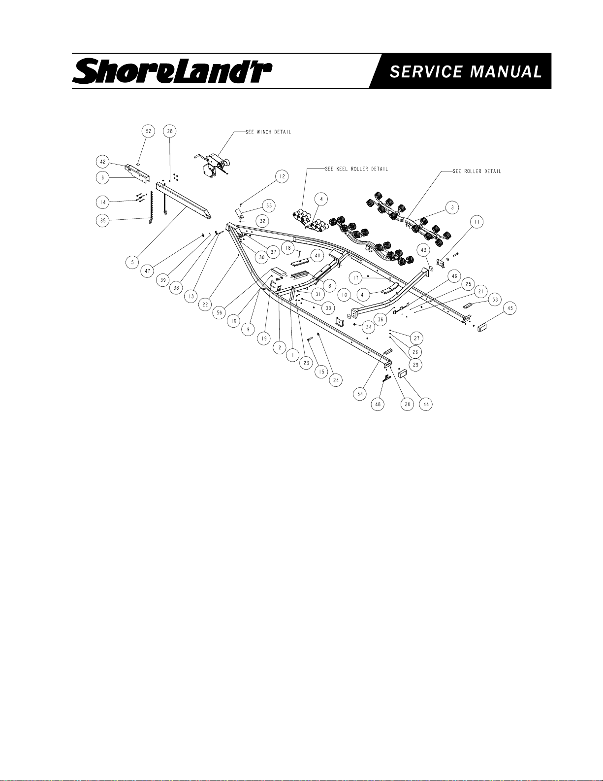
®
SLR46TB / SLR46TBB
0002814
REF# PART# DESCRIPTION QTY
1 60047-- ADJ BUNK BRKT ....................................... 2
2 6046200 ADJUSTABLE BUNK CLAMP ................... 2
3 60615-- RACKARMS 53 1/2 IN 12 ROLLERS ..... 2
4 60889-- KEEL CRADLE ASSY 6-ROLLER ............. 1
5 65541-- TONGUE 3X5X55 ...................................... 1
6 65542-- OUTER HOUSING - UFP ACTUATOR ..... 1
7 65601 BRAKELINE ASSY 56" ............................. 1
8 65781 ALUM EXT - CENTER PAD RISER 124 ... 2
9 66103-- FRAME WMENT 80 WIDE 208 LONG ...... 1
10 66129-- REAR PIVOT WMENT (80 WIDE) ............. 1
11 66540-- REAR PIVOT STOP WMENT (2X5) .......... 2
12 0110096 HH 1/2-20 X 1-1/2 ...................................... 1
13 0110114 HH 1/2-13 X 4 CS GR5 .............................. 4
14 0110120 HH 1/2-13 X 5 CS GR5 .............................. 1
15 0120281 HH 3/4-16 X 4 CS GR5 .............................. 2
16 0140040 HH 3/8-16 X 1 CS GR5 .............................. 2
17 0210130 CARR 3/8-16 X 3 3/4 GR5 ......................... 1
18 0210137 CARR 3/8-16 X 5 FULL THREAD GR5 ..... 2
19 0310228 SUB 1/2 X 3 9/16 X 4 1/4 .......................... 2
20 0810126 SCREW SELFTAP TYPE B 1/4X1/2 ......... 4
21 0810925 SCREW SELFDRILL HWH #10-16 X 3/4 .. 2
22 0810945 SCREW SELFDRILL 1/4-14X3/4 .............. 1
23 1310040 LOCKWASHER 1/2 S/T MED .................... 4
24 1310120 WASHER USS FLAT 3/4 ULTRASEALED 2
25 1310170 WASHER #10 USS FLAT .......................... 2
26 1340030 LOCKWASHER 3/8 S/T MED .................... 3
27 1340095 WASHER USS FLAT 3/8 ........................... 1
28 1340100 WASHER USS FLAT 1/2 ........................... 3
0002888
REF# PART# DESCRIPTION QTY
29 1410109 HEX NUT FINISH 3/8-16 ........................... 3
30 1410209 HEX LOCKNUT 1/2-20 .............................. 1
31 1440101 FLANGE LOCKNUT SMALL 3/8-16 .......... 2
32 1440102 FLANGE LOCKNUT SMALL 1/2-13 .......... 5
33 1440159 HEX NUT FINISH 1/2-13 ........................... 4
34 1440321 HEX LOCKNUT 3/4-16 GRB ..................... 2
35 2220272 CHAIN 8/0 MACH CHAIN 37" W/837 ........ 2
36 3510022 GROMMET 7/16IN MOLDED ................... 1
37 3510030 GROMMET 7/8IN MOLDED ..................... 12
38 3510122 LIGHT BEZEL - WHITE ............................. 2
39 3510158 PLASTIC DRIVE RIVOT ............................ 4
40 3510538 REAR CROSSMEMBER PAD ................... 2
41 3510542 MOLDED REAR CROSSMEMBER PAD .. 1
42 3991013 ACTUATOR UFP DISC BRAKE AXLE ...... 1
43 4811339 WASHER NYLON - 13/16 ID X 3-3/4 ........ 2
44 5110013 DRY LAUNCH LIGHT ASSY (LEFT) ......... 1
45 5110014 DRY LAUNCH LIGHT ASSY (RIGHT) ....... 1
46 5110045 3 LIGHT CLUSTER 1994 LEXAN ........... 1
47 5110112 MARINE YELLOW CLEARANCE LIGHT .. 2
48 5110348 BO LICENSE PLATE BRACKET ............... 1
49 5110347 HARNESS 5-PRONG FLAT .................... 1
50 5110402 HARNESS FRAME 2X4 200+ 2X5 RT .... 1
51 5110403 HARNESS FRAME 2X4 200+ 2X5 LT ..... 1
52 7010168 CAP PLASTIC OUTER MEMBER 2IN DI . 1
53 S-3390 STEP PAD RIGHT 2 1/2 X 7 .................. 1
54 S-3391 STEP PAD LEFT 2 1/2 X 7 ..................... 1
55 S-3510 TONGUE COVER PLATE ......................... 1
56 S-3553 BUNK ASSY 2X6X10" W/BRKT ................ 2
0002909
Made in the USA Midwest Industries, Inc. Ida Grove, IA 51445 (800)859-3028 0002901
www.shorelandr.com REV A 10/24/00
Page 8

Final Assembly Instructions
Remove the small parts from the frame by cutting the
bands. Remove the bolt bag and sort all nuts and bolts by
size.
Tongue:
Slide the tongue into the frame cap of the frame. Line up
the holes and fasten the tongue in the side of the frame
cap with a 1/2 X 4-1/4 hex bolt and 1/2 flange lock nut.
Fasten the tongue in the rear of the frame cap with a 1/2 X
1-1/2 hex bolt and 1/2 hex lock nut. Plug the tongue
harness into the frame harness, use grommets to secure
the wires in the wire holes.
Actuator & Safety Chain:
Slide the actuator into the actuator housing unit and secure
with two (2) pins and snap rings provided with the actuator.
Secure the actuator-housing unit to the front of the tongue
using three (3) 1/2 X 4 hex bolts and 1/2 flange lock
nuts. Using a 1/2 X 5 hex bolt on the lower right mounting
hole on the tongue, secure the safety chain. Place a 1/2
flat washer on the 1/2 X 5 hex bolt followed by one (1)
safety chain and insert into the actuator housing unit and
the tongue. Place a second safety chain on the bolt
followed by a 1/2 flat washer and 1/2 flange lock nut.
Roller Assembly:
Mount the 60615-- (53-1/2 rack arm/12-roller) assembly
on the rear pivot in a desired location that best fits your
boat. Secure this assembly by using a 1/2 X 4 carriage
bolt and a 1/2 flange lock nut. Repeat on opposite side.
Page 9
®
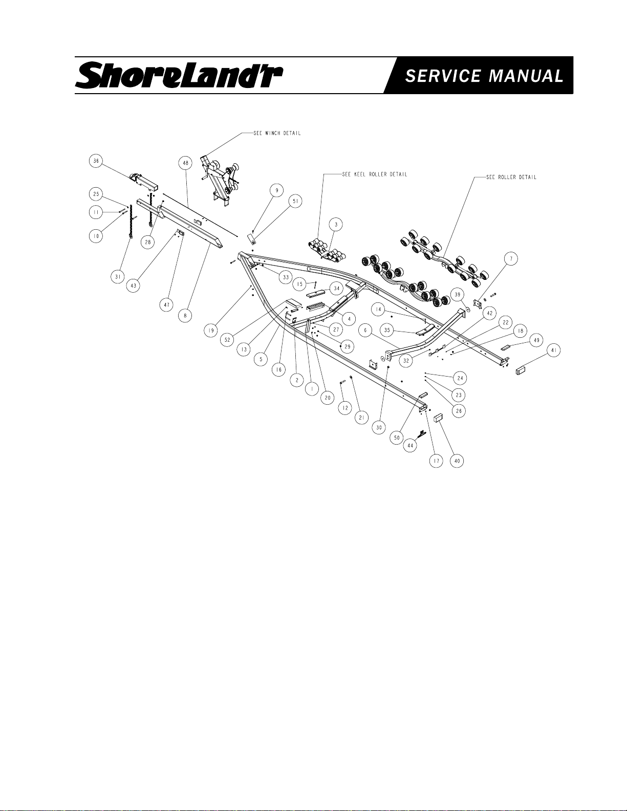
SLR55TBB
0002908
REF# PART# DESCRIPTION QTY
1 60047-- ADJ BUNK BRKT ....................................... 2
2 6046200 ADJUSTABLE BUNK CLAMP ................... 2
3 60889-- KEEL CRADLE ASSY 6-ROLLER ............. 1
4 65781 ALUM EXT - CENTER PAD RISER 124 ... 2
5 66104-- FRAME WMENT 80 WIDE 226 LONG ...... 1
6 66129-- REAR PIVOT WMENT (80 WIDE) ............. 1
7 66540-- REAR PIVOT STOP WMENT (2X5) .......... 2
8 66601-- TONGUE WMENT 63 IN FOR DEMCO .... 1
9 0110096 HH 1/2-20 X 1-1/2 ...................................... 1
10 0110114 HH 1/2-13 X 4 CS GR5 .............................. 3
11 0110120 HH 1/2-13 X 5 CS GR5 .............................. 1
12 0120281 HH 3/4-16 X 4 CS GR5 .............................. 2
13 0140040 HH 3/8-16 X 1 CS GR5 .............................. 2
14 0210130 CARR 3/8-16 X 3 3/4 GR5 ......................... 1
15 0210137 CARR 3/8-16 X 5 FULL THREAD GR5 ..... 2
16 0310228 SUB 1/2 X 3 9/16 X 4 1/4 .......................... 2
17 0810126 SCREW SELFTAP TYPE B 1/4X1/2 ......... 4
18 0810925 SCREW SELFDRILL HWH #10-16 X 3/4 .. 6
19 0810945 SCREW SELFDRILL 1/4-14X3/4 .............. 1
20 1310040 LOCKWASHER 1/2 S/T MED .................... 4
21 1310120 WASHER USS FLAT 3/4 US ..................... 2
22 1310170 WASHER #10 USS FLAT .......................... 2
23 1340030 LOCKWASHER 3/8 S/T MED .................... 3
24 1340095 WASHER USS FLAT 3/8 ........................... 1
25 1340100 WASHER USS FLAT 1/2 ........................... 3
26 1410109 HEX NUT FINISH 3/8-16 ........................... 3
0002888
REF# PART# DESCRIPTION QTY
27 1440101 FLANGE LOCKNUT SMALL 3/8-16 .......... 2
28 1440102 FLANGE LOCKNUT SMALL 1/2-13 .......... 5
29 1440159 HEX NUT FINISH 1/2-13 ........................... 4
30 1440321 HEX LOCKNUT 3/4-16 GRB ..................... 2
31 2210180 CHAIN 1/4(7MM)X 10 LINKS .................... 2
32 3510022 GROMMET 7/16IN MOLDED ................... 1
33 3510030 GROMMET 7/8IN MOLDED ..................... 12
34 3510538 REAR CROSSMEMBER PAD ................... 2
35 3510542 MOLDED REAR CROSSMEMBER PAD .. 1
36 4510499 ACTUATOR 7500LB TANDEM.................. 1
37 4510505 COUPLING-#.302X3 WTHR-HD TUBE ..... 1
38 4510520 CLAMP - BLUDOT #12090-3/16IN TUBE . 1
39 4811339 WASHER NYLON - 13/16 ID X 3-3/4 ........ 2
40 5110013 DRY LAUNCH LIGHT ASSY (LEFT) ......... 1
41 5110014 DRY LAUNCH LIGHT ASSY (RIGHT) ....... 1
42 5110045 3 LIGHT CLUSTER 1994 LEXAN ........... 1
43 5110127 REFLECTOR ANDERSON AMBER .......... 2
44 5110348 BO LICENSE PLATE BRACKET ............... 1
45 5110402 HARNESS FRAME 2X4 200+ 2X5 RT .... 1
46 5110403 HARNESS FRAME 2X4 200+ 2X5 LT ..... 1
47 5110456 LIGHT AMBER SIDE MARKER 36IN WI . 2
48 66472 DEMCOBRAKELINE ASSY 80-W DISC 10 .. 1
49 S-3390 STEP PAD RIGHT 2 1/2 X 7 .................. 1
50 S-3391 STEP PAD LEFT 2 1/2 X 7 ..................... 1
51 S-3510 TONGUE COVER PLATE ......................... 1
52 S-3553 BUNK ASSY 2X6X10" W/BRKT ................ 2
-- 5110347 HARNESS 5-PRONG FLAT ...................... 1
0002910
Made in the USA Midwest Industries, Inc. Ida Grove, IA 51445 (800)859-3028 0002902
www.shorelandr.com REV A 10/24/00
Page 10

Final Assembly Instructions
Remove the small parts from the frame by cutting the
bands. Remove the bolt bag and sort all nuts and bolts by
size.
Tongue:
Slide the tongue into the frame cap of the frame. Line up
the holes and fasten the tongue in the side of the frame
cap with a 1/2 X 4-1/4 hex bolt and 1/2 flange lock nut.
Fasten the tongue in the rear of the frame cap with a 1/2 X
1-1/2 hex bolt and 1/2 hex lock nut. Plug the tongue
harness into the frame harness, use grommets to secure
the wires in the wire holes.
Actuator & Safety Chain:
Slide the actuator into the actuator housing unit and secure
with two (2) pins and snap rings provided with the actuator.
Secure the actuator-housing unit to the front of the tongue
using three (3) 1/2 X 4 hex bolts and 1/2 flange lock
nuts. Using a 1/2 X 5 hex bolt on the lower right mounting
hole on the tongue, secure the safety chain. Place a 1/2
flat washer on the 1/2 X 5 hex bolt followed by one (1)
safety chain and insert into the actuator housing unit and
the tongue. Place a second safety chain on the bolt
followed by a 1/2 flat washer and 1/2 flange lock nut.
Roller Assembly:
Mount the 66212-- (12-roller-rack arm) assembly on the
rear pivot in a desired location that best fits your boat.
Secure this assembly by using a 1/2 X 4 carriage bolt
and a 1/2 flange lock nut. Repeat on opposite side.
Page 11

®
SLRB46TB / SLRB46TBB
0002814
0002888
REF# PART# DESCRIPTION QTY
1 60047-- ADJ BUNK BRKT ....................................... 2
2 6046200 ADJUSTABLE BUNK CLAMP ................... 2
3 60889-- KEEL CRADLE ASSY 6-ROLLER ............. 1
4 65541-- TONGUE 3X5X55 ...................................... 1
5 65542-- OUTER HOUSING - UFP ACTUATOR ..... 1
6 65601 BRAKELINE ASSY 56" ............................. 1
7 65781 ALUM EXT - CENTER PAD RISER 124 ... 2
8 66103-- FRAME WMENT 80 WIDE 208 LONG ...... 1
9 66129-- REAR PIVOT WMENT (80 WIDE) ............. 1
10 66540-- REAR PIVOT STOP WMENT (2X5) .......... 2
11 0110096 HH 1/2-20 X 1-1/2 ...................................... 1
12 0110114 HH 1/2-13 X 4 CS GR5 .............................. 4
13 0110120 HH 1/2-13 X 5 CS GR5 .............................. 1
14 0120281 HH 3/4-16 X 4 CS GR5 .............................. 2
15 0140040 HH 3/8-16 X 1 CS GR5 .............................. 2
16 0210130 CARR 3/8-16 X 3 3/4 GR5 ......................... 1
17 0210137 CARR 3/8-16 X 5 FULL THREAD GR5 ..... 2
18 0310228 SUB 1/2 X 3 9/16 X 4 1/4 .......................... 2
19 0310390 SUB 1/2 X 3 9/16 X 3 7/8 .......................... 4
20 0810126 SCREW SELFTAP TYPE B 1/4X1/2 ......... 4
21 0810925 SCREW SELFDRILL HWH #10-16 X 3/4 .. 2
22 0810945 SCREW SELFDRILL 1/4-14X3/4 .............. 1
23 1310040 LOCKWASHER 1/2 S/T MED .................... 4
24 1310120 WASHER USS FLAT 3/4 ULTRASEALED 2
25 1310170 WASHER #10 USS FLAT .......................... 2
26 1340030 LOCKWASHER 3/8 S/T MED .................... 3
27 1340095 WASHER USS FLAT 3/8 ........................... 1
28 1340100 WASHER USS FLAT 1/2 ........................... 3
29 1410109 HEX NUT FINISH 3/8-16 ........................... 3
30 1410209 HEX LOCKNUT 1/2-20 .............................. 1
REF# PART# DESCRIPTION QTY
31 1440101 FLANGE LOCKNUT SMALL 3/8-16 .......... 2
32 1440102 FLANGE LOCKNUT SMALL 1/2-13 .......... 21
33 1440159 HEX NUT FINISH 1/2-13 ........................... 4
34 1440321 HEX LOCKNUT 3/4-16 GRB ..................... 2
35 2220272 CHAIN 8/0 MACH CHAIN 37" W/837 ........ 2
36 3510022 GROMMET 7/16IN MOLDED ................... 1
37 3510030 GROMMET 7/8IN MOLDED ..................... 12
38 3510122 LIGHT BEZEL - WHITE ............................. 2
39 3510158 PLASTIC DRIVE RIVOT ............................ 4
40 3510538 REAR CROSSMEMBER PAD ................... 2
41 3510542 MOLDED REAR CROSSMEMBER PAD .. 1
42 3810097 SPACER .515ID X 11/16OD X 7/16 LG ... 8
43 3991013 ACTUATOR UFP DISC BRAKE AXLE ...... 1
44 4811339 WASHER NYLON - 13/16 ID X 3-3/4 ........ 2
45 5110013 DRY LAUNCH LIGHT ASSY (LEFT) ......... 1
46 5110014 DRY LAUNCH LIGHT ASSY (RIGHT) ....... 1
47 5110045 3 LIGHT CLUSTER 1994 LEXAN ........... 1
48 5110112 MARINE YELLOW CLEARANCE LIGHT .. 2
49 5110348 BO LICENSE PLATE BRACKET ............... 1
50 5110347 HARNESS 5-PRONG FLAT .................... 1
51 5110402 HARNESS FRAME 2X4 200+ 2X5 RT .... 1
52 5110403 HARNESS FRAME 2X4 200+ 2X5 LT ..... 1
53 7010168 CAP PLASTIC OUTER MEMBER 2IN DI . 1
54 S-3264 BUNK SUPPORT PIVOT 10 GA GALV ... 4
55 S-3390 STEP PAD RIGHT 2 1/2 X 7 .................. 1
56 S-3391 STEP PAD LEFT 2 1/2 X 7 ..................... 1
57 S-3468 3X3 63&1/2 BUNK SUPPORT TUBE ........ 2
58 S-3498 BUNK ASSY 2X6X88 3/4 RB KIT ............ 2
59 S-3510 TONGUE COVER PLATE ......................... 1
60 S-3553 BUNK ASSY 2X6X10" W/BRKT ................ 2
Made in the USA Midwest Industries, Inc. Ida Grove, IA 51445 (800)859-3028 0002903
www.shorelandr.com REV B 11/01/00
Page 12

Final Assembly Instructions
Remove the small parts from the frame by cutting the
bands. Remove the bolt bag and sort all nuts and bolts by
size.
Tongue:
Slide the tongue into the frame cap of the frame. Line up
the holes and fasten the tongue in the side of the frame
cap with a 1/2 X 4-1/4 hex bolt and 1/2 flange lock nut.
Fasten the tongue in the rear of the frame cap with a 1/2 X
1-1/2 hex bolt and 1/2 hex lock nut. Plug the tongue
harness into the frame harness, use grommets to secure
the wires in the wire holes.
Actuator & Safety Chain:
Slide the actuator into the actuator housing unit and secure
with two (2) pins and snap rings provided with the actuator.
Secure the actuator-housing unit to the front of the tongue
using three (3) 1/2 X 4 hex bolts and 1/2 flange lock
nuts. Using a 1/2 X 5 hex bolt on the lower right mounting
hole on the tongue, secure the safety chain. Place a 1/2
flat washer on the 1/2 X 5 hex bolt followed by one (1)
safety chain and insert into the actuator housing unit and
the tongue. Place a second safety chain on the bolt
followed by a 1/2 flat washer and 1/2 flange lock nut.
Bunk Assembly:
Pre-assemble the bunks as described prior to installing on
the rear pivot. Lay the carpeted bunks upside down so the
u-bolts under the bunks are facing up. Install the bunk
saddle over the u-bolt so that the curve in the saddle
matches the curve in the 16 bunk bracket. Install the large
bunk support tube over the u-bolts. With the u-bolts
protruding through the support tube, install the 7/16
spacers over the u-bolts. Install 1/2 flat washers and 1/2
hex lock nuts. Tighten. Repeat for the other side. If
properly assembled the bunk will freely pivot when the ubolts are tight.
Fasten the front portion of the bunks to the 2X6 bunk
bracket with 1-1/4 screws.
Page 13

®
SLRB55TBB
0002908
0002888
REF# PART# DESCRIPTION QTY
1 60047-- ADJ BUNK BRKT ....................................... 2
2 6046200 ADJUSTABLE BUNK CLAMP ................... 2
3 60889-- KEEL CRADLE ASSY 6-ROLLER ............. 1
4 65781 ALUM EXT - CENTER PAD RISER 124 ... 2
5 66104-- FRAME WMENT 80 WIDE 226 LONG ...... 1
6 66129-- REAR PIVOT WMENT (80 WIDE) ............. 1
7 6654000 REAR PIVOT STOP WMENT (2X5) .......... 2
8 66601-- TONGUE WMENT 63 IN FOR DEMCO .... 1
9 0110096 HH 1/2-20 X 1-1/2 ...................................... 1
10 0110114 HH 1/2-13 X 4 CS GR5 .............................. 3
11 0110120 HH 1/2-13 X 5 CS GR5 .............................. 1
12 0120281 HH 3/4-16 X 4 CS GR5 .............................. 2
13 0140040 HH 3/8-16 X 1 CS GR5 .............................. 2
14 0210130 CARR 3/8-16 X 3 3/4 GR5 ......................... 1
15 0210137 CARR 3/8-16 X 5 FULL THREAD GR5 ..... 2
16 0310228 SUB 1/2 X 3 9/16 X 4 1/4 .......................... 2
17 0310390 SUB 1/2 X 5 9/16 X 3 ................................. 4
18 0810126 SCREW SELFTAP TYPE B 1/4X1/2 ......... 4
19 0810925 SCREW SELFDRILL HWH #10-16 X 3/4 .. 6
20 0810945 SCREW SELFDRILL 1/4-14X3/4 .............. 1
21 1310040 LOCKWASHER 1/2 S/T MED .................... 4
22 1310120 WASHER USS FLAT 3/4 US ..................... 2
23 1310170 WASHER #10 USS FLAT .......................... 2
24 1340030 LOCKWASHER 3/8 S/T MED .................... 3
25 1340095 WASHER USS FLAT 3/8 ........................... 1
26 1340100 WASHER USS FLAT 1/2 ........................... 3
27 1410109 HEX NUT FINISH 3/8-16 ........................... 3
28 1440101 FLANGE LOCKNUT SMALL 3/8-16 .......... 2
REF# PART# DESCRIPTION QTY
29 1440102 FLANGE LOCKNUT SMALL 1/2-13 .......... 21
30 1440159 HEX NUT FINISH 1/2-13 ........................... 4
31 1440321 HEX LOCKNUT 3/4-16 GRB ..................... 2
32 2210180 CHAIN 1/4(7MM)X 10 LINKS .................... 2
33 3510022 GROMMET 7/16IN MOLDED ................... 1
34 3510030 GROMMET 7/8IN MOLDED ..................... 12
35 3510538 REAR CROSSMEMBER PAD ................... 2
36 3510542 MOLDED REAR CROSSMEMBER PAD .. 1
37 3810097 SPACER .515ID X 11/16OD X 7/16 LG ... 8
38 4510499 ACTUATOR 7500LB TANDEM.................. 1
39 4510505 COUPLING - NO.302X3 WTHR-HD TUBE 1
40 4811339 WASHER NYLON - 13/16 ID X 3-3/4 ........ 2
41 5110013 DRY LAUNCH LIGHT ASSY (LEFT) ......... 1
42 5110014 DRY LAUNCH LIGHT ASSY (RIGHT) ....... 1
43 5110045 3 LIGHT CLUSTER 1994 LEXAN ........... 1
44 5110127 REFLECTOR ANDERSON AMBER .......... 2
45 5110348 BO LICENSE PLATE BRACKET ............... 1
46 5110347 HARNESS 5-PRONG FLAT .................... 1
47 5110402 HARNESS FRAME 2X4 200+ 2X5 RT .... 1
48 5110403 HARNESS FRAME 2X4 200+ 2X5 LT ..... 1
49 5110456 LIGHT AMBER SIDE MARKER 36IN WI . 2
50 66472 DEMCOBRAKELINE ASSY 80-W DISC 101 1
51 S-3264 BUNK SUPPORT PIVOT 10 GA GALV ... 4
52 S-3390 STEP PAD RIGHT 2 1/2 X 7 .................. 1
53 S-3391 STEP PAD LEFT 2 1/2 X 7 ..................... 1
54 S-3468 3X3 63&1/2 BUNK SUPPORT TUBE ........ 2
55 S-3498 BUNK ASSY 2X6X88 3/4 RB KIT ............ 2
56 S-3510 TONGUE COVER PLATE ......................... 1
57 S-3553 BUNK ASSY 2X6X10" W/BRKT ................ 2
Made in the USA Midwest Industries, Inc. Ida Grove, IA 51445 (800)859-3028 0002904
www.shorelandr.com REV A 10/24/00
Page 14

Final Assembly Instructions
Remove the small parts from the frame by cutting the
bands. Remove the bolt bag and sort all nuts and bolts by
size.
Tongue:
Slide the tongue into the frame cap of the frame. Line up
the holes and fasten the tongue in the side of the frame
cap with a 1/2 X 4-1/4 hex bolt and 1/2 flange lock nut.
Fasten the tongue in the rear of the frame cap with a 1/2 X
1-1/2 hex bolt and 1/2 hex lock nut. Plug the tongue
harness into the frame harness, use grommets to secure
the wires in the wire holes.
Actuator & Safety Chain:
Slide the actuator into the actuator housing unit and secure
with two (2) pins and snap rings provided with the actuator.
Secure the actuator-housing unit to the front of the tongue
using three (3) 1/2 X 4 hex bolts and 1/2 flange lock
nuts. Using a 1/2 X 5 hex bolt on the lower right mounting
hole on the tongue, secure the safety chain. Place a 1/2
flat washer on the 1/2 X 5 hex bolt followed by one (1)
safety chain and insert into the actuator housing unit and
the tongue. Place a second safety chain on the bolt
followed by a 1/2 flat washer and 1/2 flange lock nut.
Bunk Assembly:
Pre-assemble the bunks as described prior to installing on
the rear pivot. Lay the carpeted bunks upside down so the
u-bolts under the bunks are facing up. Install the bunk
saddle over the u-bolt so that the curve in the saddle
matches the curve in the 16 bunk bracket. Install the large
bunk support tube over the u-bolts. With the u-bolts
protruding through the support tube, install the 7/16
spacers over the u-bolts. Install 1/2 flat washers and 1/2
hex lock nuts. Tighten. Repeat for the other side. If
properly assembled the bunk will freely pivot when the ubolts are tight.
Fasten the front portion of the bunks to the 2X6 bunk
bracket with 1-1/4 screws.
Page 15

®
Chassis 46TB
REF# PART# DESCRIPTION QTY
25 1440101 FLANGE LOCKNUT SMALL 3/8-16 .......... 6
26 1440102 FLANGE LOCKNUT SMALL 1/2-13 .......... 24
27 1440259 HEX LOCKNUT 9/16-18 GRA ................... 8
28 1440319 HEX NUT 3/4-16 UNF ................................ 2
29 1440349 HEX NUT SLOTTED PLAIN ...................... 2
30 1540038 COTTER KEY 1/8 X 1 1/2 ......................... 2
31 3510122 LIGHT BEZEL - WHITE ............................. 4
REF# PART# DESCRIPTION QTY
1 4279 SHIM PAD U BOLT 12GA FRAME ......... 4
2 60880-- FENDER 9IN POLY RF/LR ...................... 2
3 60887-- FENDER 9IN POLY LF/RR ...................... 2
4 6239200 TANDEM BOGIE 2X5 .............................. 2
5 66155-- AXLE WMENT (80 WIDE) ......................... 2
6 66163-- SPRING BRKT 9IN TANDEM .................. 2
7 66167-- AXLE ASSY80 WIDE ................................. 1
8 66439-- AXLE ASSY 80 WIDE W/BRAKES ............ 1
9 66472 BRAKE LINE ASSY 105" ........................... 1
10 0110170 HH 9/16-18 X 3 1/4 CS GR5 ...................... 8
11 0110282 HH 3/4-10 X 4 1/2 CS GR5 ........................ 2
12 0140047 HH 3/8-16 X 1 3/4 CS GR5 ........................ 4
13 0210058 CARR 5/16-18 X 1 GR5 ............................. 8
14 0210130 CARR 3/8-16 X 3 3/4 GR5 ......................... 2
15 0310170 SUB 1/2" X 2-5/16"X6-1/2 .......................... 8
16 0310280 SUB 1/2 X 2 9/16 X 7 5/8 .......................... 4
17 0610042 SOCKET HEAD SCREW 7/16-20X1-1/4 ... 4
18 0810920 SCREW SELFTAP TYPE A #10X1 1 ........ 4
19 1310025 LOCKWASHER 5/16 S/T MED .................. 8
20 1310035 LOCKWASHER 7/16 S/T ........................... 4
21 1310163 WASHER 1.377 OD X .390 ID ................... 8
22 1340206 WASHER 1.5 OD X .765 ID X .186/.206 ... 2
23 1410069 HEX NUT FINISH 5/16-18 ......................... 8
24 1410229 HEX LUGNUT 1/2-20 13/16 OD Z&U ........ 20
32 3510132 AXLE PAD 12IN BLK ................................ 2
33 3510158 PLASTIC DRIVE RIVOT ............................ 8
34 3610050 BUSHING 3/4 IDX1 ODX1 1/2 BRONZE . 2
35 4300218 ST185/80R13C TIRE/MSILVER DIR RIM . 4
-- 4300215 ST185/80R13C TIRE/GALV DIR RIM ....... 4
36 4410089 SPINDLE SLEEVE 1 1/4-3/4IN BRG ........ 4
37 4410130 SEAL 1 3/8IN ............................................ 2
38 4410246 SL BEARING PROTECTOR BRA ............. 2
39 4410247 BEARING BUDDY - STAINLESS STEEL.. 2
40 4410289 DISC BRAKE CALIPER ASSY .................. 1
41 4410290 DISC BRAKE CALIPER ASSY .................. 1
42 4410291 SUBASSY DICO 10" BRAKE DRUM......... 2
43 4440160 ROLLER BEARING 1 1/16IN ................... 2
44 4440170 ROLLER BEARING 1 3/8IN..................... 2
45 4470400 HUB 1 3/8 X 1 1/16 CAST ....................... 2
46 4510506 PLUG.......................................................... 1
47 4510511 HOSE - 18IN MALE-FEMALE BRAKE ...... 1
48 4510518 HOSE CLIP - 1457-YZ ............................... 1
49 4610072 SPRING 5 LEAF HOOK ........................... 4
50 5110112 MARINE YELLOW CLEARANCE LIGHT .. 2
51 5110113 MARINE RED CLEARANCE LIGHT .......... 2
52 S-3387 2" PLASTIC CHANNEL BRACKET ........... 2
53 S-3501 RUBBER CUP WASHER ........................... 8
54 S-3409G SPRING CLAMP 1/4X1 1/2X4 ZYU ....... 4
55 S-3449G SPRING AND AXLE U-BOLT PLATE ........ 4
Made in the USA Midwest Industries, Inc. Ida Grove, IA 51445 (800)859-3028 0002905
www.shorelandr.com REV A 11/01/00
Page 16

Final Assembly Instructions
Rocker Boxes:
Align the center hole of the 6239210, rocker arm, with the
center hole of the spring bracket. Secure with a 3/4 X 4-1/
2 hex bolt, from the outside-in, and 3/4 hex lock nut with
the grease zerk down.
Axles:
Fasten the springs to the axles with the axle u-bolts, spring
plate and hex lock nuts. NOTE: Make certain the hook end
of the springs point in the same direction to the rear of the
trailer, on both axles! For the rear spring and axle place a
S-3207 galvanized spring bracket bushing in the rear of
the spring bracket. Insert a 9/16 X 3-1/4 hex bolt through
the bracket from the outside-in and tighten with a 9/16 hex
lock nut. Slide the end of the hook spring over the bushing;
raise the front of the spring and fasten with a 9/16 X 3-1/4
hex bolt and 9/16 hex lock nut.
For installation of the front spring and axle repeat the
above instructions, however, place the bushing in the
rocker box in hook end of the spring. Insert bolts and
secure with lock nuts as before.
Mount the tire and rim assemblies using 80-90 ft. lbs.
torque on the lug nuts.
Tire Size & Carrying Capacity Chart
Tire Load Carrying
Size Range Capacity
ST185/80R13 C 1480 lbs. per/tire
Refer to the tire side wall for the correct tire pressure.
Brakes:
Refer to the brake manual for service and maintenance.
Page 17

®
Chassis 46TBB
REF# PART# DESCRIPTION QTY
1 4279 SHIM PAD U BOLT 12GA FRAME ......... 4
2 60880-- FENDER 9IN POLY RF/LR ...................... 2
3 60887-- FENDER 9IN POLY LF/RR ...................... 2
4 61609 BRAKELINE ASSY 40IN........................... 1
5 6239200 TANDEM BOGIE 2X5 .............................. 2
6 66155-- AXLE WMENT (80 WIDE) ......................... 2
7 66163-- SPRING BRKT 9IN TANDEM .................. 2
8 66439-- AXLE ASSY 80 WIDE W/BRAKES ............ 2
9 66472 BRAKE LINE ASSY 105" ........................... 2
10 0110170 HH 9/16-18 X 3 1/4 CS GR5 ...................... 8
11 0110282 HH 3/4-10 X 4 1/2 CS GR5 ........................ 2
12 0140047 HH 3/8-16 X 1 3/4 CS GR5 ........................ 4
13 0210058 CARR 5/16-18 X 1 GR5 ............................. 8
14 0210130 CARR 3/8-16 X 3 3/4 GR5 ......................... 2
15 0310170 SUB 1/2" X 2-5/16"X6-1/2 .......................... 8
16 0310276 SUB 1/2 X 2 9/16 X 6 1/2 .......................... 4
17 0610042 SOCKET HEAD SCREW 7/16-20X1-1/4 ... 8
18 0810920 SCREW SELFTAP TYPE A #10X1 1 ........ 4
19 1310025 LOCKWASHER 5/16 S/T MED .................. 8
20 1310035 LOCKWASHER 7/16 S/T ........................... 8
21 1310163 WASHER 1.377 OD X .390 ID ................... 8
22 1340206 WASHER 1.5 OD X .765 ID X .186/.206 ... 4
23 1410069 HEX NUT FINISH 5/16-18 ......................... 8
24 1410229 HEX LUGNUT 1/2-20 13/16 OD Z&U ........ 20
25 1440101 FLANGE LOCKNUT SMALL 3/8-16 .......... 6
26 1440102 FLANGE LOCKNUT SMALL 1/2-13 .......... 24
27 1440259 HEX LOCKNUT 9/16-18 GRA ................... 8
28 1440319 HEX NUT 3/4-16 UNF ................................ 2
REF# PART# DESCRIPTION QTY
29 1440349 HEX NUT SLOTTED PLAIN ...................... 4
30 1540038 COTTER KEY 1/8 X 1 1/2 ......................... 4
31 3510122 LIGHT BEZEL - WHITE ............................. 4
32 3510132 AXLE PAD 12IN BLK ................................ 2
33 3510158 PLASTIC DRIVE RIVOT ............................ 8
34 4300215 ST185/80R13C TIRE/GALV DIR RIM ....... 4
-- 4300218 ST185/80R13C TIRE/MSILVER DIR RIM . 4
35 4410089 SPINDLE SLEEVE 1 1/4-3/4IN BRG ........ 4
36 4410130 SEAL 1 3/8IN ............................................ 4
37 4410246 SL BEARING PROTECTOR BRA ............. 4
38 4410247 BEARING BUDDY - STAINLESS STEEL.. 4
39 4410289 DISC BRAKE CALIPER ASSY .................. 2
40 4410290 DISC BRAKE CALIPER ASSY .................. 2
41 4410291 HUB/VENTED ROTOR, C.B., ASSY, 13 ... 4
42 4410291 SUBASSY DICO 10" BRAKE DRUM......... 4
43 4440160 ROLLER BEARING 1 1/16IN ................... 4
44 4440170 ROLLER BEARING 1 3/8IN..................... 4
45 4510506 PLUG.......................................................... 1
46 4510511 HOSE - 18IN MALE-FEMALE BRAKE ...... 1
47 4510515 3/16 MALE RUN INVERTED FLARE ........ 1
48 4510518 HOSE CLIP - 1457-YZ ............................... 1
49 4610072 SPRING 5 LEAF HOOK ........................... 4
50 5110112 MARINE YELLOW CLEARANCE LIGHT .. 2
51 5110113 MARINE RED CLEARANCE LIGHT .......... 2
52 4510511 FRONTHOSE-18 MALE-FEMALE BRK ... 1
53 S-3387 2" PLASTIC CHANNEL BRACKET ........... 2
54 S-3501 RUBBER CUP WASHER ........................... 8
55 S-3409G SPRING CLAMP 1/4X1 1/2X4 ZYU ....... 4
56 S-3449G SPRING AND AXLE U-BOLT PLATE ........ 4
Made in the USA Midwest Industries, Inc. Ida Grove, IA 51445 (800)859-3028 0002906
www.shorelandr.com REV A 11/01/00
Page 18

Final Assembly Instructions
Rocker Boxes:
Align the center hole of the 6239210, rocker arm, with the
center hole of the spring bracket. Secure with a 3/4 X 4-1/
2 hex bolt, from the outside-in, and 3/4 hex lock nut with
the grease zerk down.
Axles:
Fasten the springs to the axles with the axle u-bolts, spring
plate and hex lock nuts. NOTE: Make certain the hook end
of the springs point in the same direction to the rear of the
trailer, on both axles! For the rear spring and axle place a
S-3207 galvanized spring bracket bushing in the rear of
the spring bracket. Insert a 9/16 X 3-1/4 hex bolt through
the bracket from the outside-in and tighten with a 9/16 hex
lock nut. Slide the end of the hook spring over the bushing;
raise the front of the spring and fasten with a 9/16 X 3-1/4
hex bolt and 9/16 hex lock nut.
For installation of the front spring and axle repeat the
above instructions, however, place the bushing in the
rocker box in hook end of the spring. Insert bolts and
secure with lock nuts as before.
Mount the tire and rim assemblies using 80-90 ft. lbs.
torque on the lug nuts.
Tire Size & Carrying Capacity Chart
Tire Load Carrying
Size Range Capacity
ST185/80R13 C 1480 lbs. per/tire
Refer to the tire side wall for the correct tire pressure.
Brakes:
Refer to the brake manual for service and maintenance.
Page 19

®
Chassis 55TBB
REF# PART# DESCRIPTION QTY
1 4279 SHIM PAD U BOLT 12GA FRAME ......... 4
2 60954-- FENDER 10IN POLY RR/LF ................... 2
3 60955-- FENDER 10IN POLY LR/RF ................... 2
4 62384-- SPRING BRKT 10IN TANDEM ................ 2
5 6239200 TANDEM BOGIE 2X5 .............................. 2
6 66155-- AXLE WMENT (80 WIDE) ......................... 2
7 66439-- AXLE ASSY 80 WIDE W/BRAKES ............ 2
8 66472 BRAKE LINE ASSY 105" ........................... 2
9 0110170 HH 9/16-18 X 3 1/4 CS GR5 ...................... 8
10 0110282 HH 3/4-10 X 4 1/2 CS GR5 ........................ 2
11 0140040 HH 3/8-16 X 1 CS GR5 .............................. 8
12 0140047 HH 3/8-16 X 1 3/4 CS GR5 ........................ 4
13 0210130 CARR 3/8-16 X 3 3/4 GR5 ......................... 2
14 0310170 SUB 1/2" X 2-5/16"X6-1/2 .......................... 8
15 0310280 SUB 1/2 X 2 9/16 X 7 5/8 .......................... 4
16 0610042 SOCKET HEAD SCREW 7/16-20X1-1/4 ... 8
17 0810920 SCREW SELFTAP TYPE A #10X1 1 ........ 4
18 1310035 LOCKWASHER 7/16 S/T ........................... 8
19 1310163 WASHER 1.377 OD X .390 ID ................... 16
20 1410229 HEX LUGNUT 1/2-20 13/16 OD Z&U ........ 1
21 1440101 FLANGE LOCKNUT SMALL 3/8-16 .......... 14
22 1440102 FLANGE LOCKNUT SMALL 1/2-13 .......... 24
23 1440259 HEX LOCKNUT 9/16-18 GRA ................... 8
REF# PART# DESCRIPTION QTY
24 1440319 HEX NUT 3/4-16 UNF ................................ 2
25 3510122 LIGHT BEZEL - WHITE ............................. 4
26 3510132 AXLE PAD 12IN BLK ................................ 2
27 3510158 PLASTIC DRIVE RIVOT ............................ 8
28 4300198 ST215/75R 14C TIRE/GALV DIR RIM ...... 4
-- 4300199 ST215/75R 14C TIRE/MSILVER DIR RIM 4
29 4410089 SPINDLE SLEEVE 1 1/4-3/4IN BRG ........ 4
30 4410289 DISC BRAKE CALIPER ASSY .................. 2
31 4410290 DISC BRAKE CALIPER ASSY .................. 2
32 4410291 SUBASSY DICO 10" BRAKE DRUM......... 4
33 4510506 PLUG.......................................................... 2
34 4510511 HOSE - 18" MALE-FEMALE BRAKE......... 1
35 4510515 3/16MALE RUN INVERTED FLARE ......... 1
36 4610073 SPRING 5 LEAF HOOK ........................... 4
37 5110112 MARINE YELLOW CLEARANCE LIGHT .. 2
38 5110113 MARINE RED CLEARANCE LIGHT .......... 2
39 4510511 HOSE - 18IN MALE-FEMALE BRAKE ...... 1
-- 4510511 FRNT-14HOSE-18 MALE/FEMALE BRK . 1
40 61609 BRAKELINE ASSY 40IN........................... 1
41 S-3387 2" PLASTIC CHANNEL BRACKET ........... 2
42 S-3501 RUBBER CUP WASHER ........................... 16
43 S-3207G SPRING BRKT BUSHING PLATED ZYU .. 4
44 S-3409G SPRING CLAMP 1/4X1 1/2X4 ZYU ....... 4
45 S-3449G SPRING AND AXLE U-BOLT PLATE ........ 4
Made in the USA Midwest Industries, Inc. Ida Grove, IA 51445 (800)859-3028 0002907
www.shorelandr.com REV A 11/01/00
Page 20

Final Assembly Instructions
Rocker Boxes:
Align the center hole of the 6239210, rocker arm, with the
center hole of the spring bracket. Secure with a 3/4 X 4-1/
2 hex bolt, from the outside-in, and 3/4 hex lock nut with
the grease zerk down.
Axles:
Fasten the springs to the axles with the axle u-bolts, spring
plate and hex lock nuts. NOTE: Make certain the hook end
of the springs point in the same direction to the rear of the
trailer, on both axles! For the rear spring and axle place a
S-3207 galvanized spring bracket bushing in the rear of
the spring bracket. Insert a 9/16 X 3-1/4 hex bolt through
the bracket from the outside-in and tighten with a 9/16 hex
lock nut. Slide the end of the hook spring over the bushing;
raise the front of the spring and fasten with a 9/16 X 3-1/4
hex bolt and 9/16 hex lock nut.
For installation of the front spring and axle repeat the
above instructions, however, place the bushing in the
rocker box in hook end of the spring. Insert bolts and
secure with lock nuts as before.
Mount the tire and rim assemblies using 80-90 ft. lbs.
torque on the lug nuts.
Tire Size & Carrying Capacity Chart
Tire Load Carrying
Size Range Capacity
ST215/75R14 C 1870 lbs. per/tire
Refer to the tire side wall for the correct tire pressure.
Brakes:
Refer to the brake manual for service and maintenance.
Page 21

®
SL WINCH ASSEMBLY
REF# PART# DESCRIPTION QTY
1 6107503 END CAP - BLACK PROFILE 2000 .......... 4
2 0110114 HH 1/2-13 X 4 CS GR5 .............................. 3
3 0110125 HH 1/2-13 X 5 1/2 CS GR5 ........................ 2
4 0140040 HH 3/8-16 X 1 CS GR5 .............................. 3
5 0140090 HH 1/2-13 X 1 CS GR5 .............................. 2
6 0210102 CARR 3/8-16 X 1 GR5 ............................... 1
7 0340200 SUB 1/2 X 3 9/16 X 6 W/2 3/8 THR .......... 2
8 1310040 LOCKWASHER 1/2 S/T MED .................... 3
9 1340095 WASHER USS FLAT 3/8 ........................... 2
10 1440101 FLANGE LOCKNUT SMALL 3/8-16 .......... 4
11 1440102 FLANGE LOCKNUT SMALL 1/2-13 .......... 8
12 1440159 HEX NUT FINISH 1/2-13 ........................... 3
13 2210145 CHAIN 1/4(7MM)X 10 LINKS .................... 1
14 3110242 WINCH HANDLE ....................................... 1
15 3110345 WINCH DL1800A W/STRAP-NO HANDLE 1
16 3510065 4" BOW ROLLER - BLACK ........................ 2
17 3510539 CAP BLACK FOR 3X4 WINCH CAP ......... 1
18 LH308 CUP WASHER ........................................... 4
19 S-534 WINCH POST ............................................ 1
20 S-2266 22&3/4 WINCH HOLDER CHANNEL ....... 1
21 S-2268L BOW PIVOT PLATE - LEFT ...................... 1
22 S-2268R BOW PIVOT PLATE - RIGHT .................... 1
Winch Post:
Position the winch post assembly on the tongue of your trailer.
Secure with two (2) 1/2 X 3-9/16 X 6 square u-bolts and 1/2
flange lock nuts. Leave loose for adjustment. Fasten the winch
handle to the winch.
Bow Eye Safety Chain:
Insert a 3/8 X 1 carriage bolt from the top through the square
hole at the end of the winch holder channel. Place the last link of
the safety chain onto the bolt, then 3/8 flat washer and 3/8 flange
lock nut. Tighten.
Winch Post Adjustment:
Once the boat is positioned on the trailer, adjust the winch post to
the boat. Loosen the three (3) 1/2 X 4 hex bolts and move the
winch bracket so that the top rubber bow roller is above the bow
eye. Tighten.
Slide the winch post assembly against the boat. Tighten the ubolts. Adjustment is complete. Check the tongue weight before
tightening the u-bolts.
Made in the USA Midwest Industries, Inc. Ida Grove, IA 51445 (800)859-3028 0002908
www.shorelandr.com REV 8/31/00
Page 22

Page 23

®
Profile 2000 Winch Assembly
REF# PART# DESCRIPTION QTY
1 6081610 WINCH POST SPACER 1
2 60930-- WINCH POST 7IN ................................... 1
3 6107503 END CAP - BLACK PROFILE 2000 .......... 2
4 65657-- WINCH HOLDER CASE ............................ 1
5 65659-- PROFILE 2000 WINCH CASE ASSY ........ 1
6 0110064 HH 3/8-16 X 5 CS GR5 .............................. 1
7 0110118 HH 1/2-13 X 4 1/2 CS GR5 ........................ 5
8 0110125 HH 1/2-13 X 5 1/2 CS GR5 ........................ 1
9 204009 SHAFT BUSHING DL1400/2500 .............. 2
10 204360 SPACER WASHER DL1602 ..................... 1
11 204808 REEL SPACER DL1700 ........................... 1
12 204809 HANDLE HUT DL1602 ............................. 1
13 205014 LOCK NUT DL1400/1700/1802/2500 ....... 1
14 205116 E-RING DL1602/1700/2500 ....................... 1
15 205126 HH 3/8-16 X 5 CS GR5 .............................. 1
16 205139 SPACER WASHER DL1700/1802/2500.... 1
17 205269 RATCHET PAWL BOLT 1/4-20 X 5........... 1
18 205270 LOCKNUT 3/8-16 JAM STYLE - WINCH .. 1
19 206281 EXTENSION SPRING DL1400-2500 BLU 1
20 0210102 CARR 3/8-16 X 1 GR5 ............................... 1
21 304731 DRIVE SHAFT UPPER DL1802 ............... 1
22 404868 REVERSABLE RATCHET PAWL .............. 1
23 404872 RACHET SPACER DL1700/2500............. 1
24 404878 RATCHET SLEEVE DL1700/2500 ........... 1
25 1340095 WASHER USS FLAT 3/8 ........................... 1
26 1440101 FLANGE LOCKNUT SMALL 3/8-16 .......... 2
27 1440102 FLANGE LOCKNUT SMALL 1/2-13 .......... 6
28 2210145 CHAIN 1/4(7MM)X 10 LINKS .................... 1
29 3110237 WINCH HANDLE DL1802 ......................... 1
30 3110348 WINCH REEL W/STRAP DL1800/1802 ... 1
31 3510065 4" BOW ROLLER - BLACK ........................ 1
32 3520011 PLUG 3/8IN WHITE PLASTIC .................. 4
33 3520019 PLUG 1IN WHITE PLASTIC ..................... 2
34 LH308 CUP WASHER ........................................... 2
35 S-3374 NYLN WINCH CASE BUSH-3/4ODX4.25 . 1
Winch Post Assembly:
Mount the winch post to the tongue in the desired position and
secure with three (3) 1/2 X 4 carriage bolts and 1/2 flange lock
nuts. Mount the winch handle on the winch shaft using the special
hardware provided with the winch.
Winch Post Adjustment:
Before adjusting the winch post check to see that the transom of
the boat is flush with the rear of bunks. Slide the winch post into
position. NOTE: The winch holder (upper portion) must be
positioned just above the bow eye. Run the winch strap over the
upper nylon bushing in the winch case and secure to the bow eye.
Tighten all bolts on the winch post. Slip the bow eye safety chain
into the bow eye. Adjustment is complete.
Made in the USA Midwest Industries, Inc. Ida Grove, IA 51445 (800)859-3028 0002814
www.shorelandr.com
REV - 7/11/00
Page 24

Page 25

®
60615-- 12-Roller Assembly - 53-1/2 Rack Arms
REF# PART# DESCRIPTION QTY
1 0110118 HH 1/2-13 X 4 1/2 CS GR5 ........................ 2
2 0210127 CARR 3/8-24 X 3 W/1 THRD GR8 ............ 8
3 0210218 CARR 1/2-13 X 4 GR5 ............................... 1
4 1310121 WASHER USS ALUMINUM FLAT 3/4 ....... 12
5 1440100 HEX LOCKNUT 3/8-24 GRA ..................... 8
6 1440102 FLANGE LOCKNUT SMALL 1/2-13 .......... 3
7 1540350 BULL RING PLAIN..................................... 12
8 S-3184 PLASTIC MOLDED SWIVEL BLOCK ........ 4
9 S-3368 INLINE ROLLERPIN 19 1/2 ....................... 4
10 S-3382 ROLLER WITH MOLDED HUB 5IN ......... 12
11 S-3383 ROLLER BUSHING MOLDED ................... 12
12 S-3384 FLAT WASHER 2OD X 1.150ID ALUM ... 12
13 S-3410 T BAR ROLLER PIN .................................. 2
14 S-3480 ROLLER ARM 18&7/8 ............................... 2
15 S-3482 ROLLER RACK ARM WMENT 53&1/2 .... 1
Rear Roller Rack:
The rear roller rack is factory assembled.
Rear Roller Rack Adjustments:
Place the boat onto the trailer so that it is resting on the rollers.
Position the boat front to back by having the center of the rear
roller approximately 4 from the transom. The boat must be
positioned so that it supported by the rollers. Once the boat is
positioned make the following roller adjustments.
Position the racks in back so that they are located between the
keels or strakes and so that they wont interfere when loading and
unloading. Once positioned, tighten the u-bolts in the mounting
brackets. The up-down adjustment in the rear adjustable mounting
bracket should be in its down position whenever possible to keep
the center of gravity lower to the ground for better trailering. The
upper position should be used only when the fender or frame
clearance is needed.
Made in the USA Midwest Industries, Inc. Ida Grove, IA 51445 (800)859-3028 0002909
www.shorelandr.com REV 8/31/00
Page 26

Page 27

®
66212-- 12-Roller Rack Arm Assembly
REF# PART# DESCRIPTION QTY
1 60972 ROLLER WITH MOLDED HUB 6IN ......... 12
2 0110118 HH 1/2-13 X 4 1/2 CS GR5 ........................ 2
3 0210127 CARR 3/8-24 X 3 W/1 THRD GR8 ............ 8
4 0210218 CARR 1/2-13 X 4 GR5 ............................... 1
5 1310121 WASHER USS ALUMINUM FLAT 3/4 ....... 12
6 1440100 HEX LOCKNUT 3/8-24 GRA ..................... 8
7 1440102 FLANGE LOCKNUT SMALL 1/2-13 .......... 3
8 1540350 BULL RING PLAIN..................................... 12
9 S-3184 PLASTIC MOLDED SWIVEL BLOCK ........ 4
10 S-3368 INLINE ROLLERPIN 19 1/2 ....................... 4
11 S-3383 ROLLER BUSHING MOLDED ................... 12
12 S-3384 FLAT WASHER 2OD X 1.150ID ALUM ... 12
13 S-3410 T BAR ROLLERPIN ................................... 2
14 S-3480 ROLLER ARM 18&7/8 ............................... 2
15 S-3482 ROLLER RACK ARM WMENT 53&1/2 .... 1
Rear Roller Rack:
The rear roller rack is factory assembled.
Rear Roller Rack Adjustments:
Place the boat onto the trailer so that it is resting on the rollers in
the back of the trailer and on the front keel support rollers up front.
Position the boat front to back by having the center of the rear
roller approximately 4 from the transom. The boat must be
positioned so that it supported by the rollers. Once the boat is
positioned make the following roller adjustments.
Position the racks in back so that they are located between the
keels or strakes and so that they wont interfere when loading and
unloading. Once positioned, tighten the u-bolts in the mounting
brackets. The up-down adjustment in the rear adjustable mounting
bracket should be in its down position whenever possible to keep
the center of gravity lower to the ground for better trailering. The
upper position should be used only when the fender or frame
clearance is needed.
Made in the USA Midwest Industries, Inc. Ida Grove, IA 51445 (800)859-3028 0002910
www.shorelandr.com REV 8/31/00
Page 28

Page 29

®
60889-- Keel Roller Assembly
REF# PART# DESCRIPTION QTY
1 60883-- KEEL CRADLE .......................................... 1
2 6088410 KEEL CRADLE ROLLER PIN .................... 6
3 60885-- KEEL GUIDE ROLLER BRACKET ............ 2
4 6205210 KEEL CRADLE ROLLER PIN .................... 1
5 6210810 RISER BRKT KEEL GUIDE ROLLER ....... 1
6 65528 8IN KEEL ROLLER .................................... 6
7 0140040 HH 3/8-16 X 1 CS GR5 .............................. 6
8 1440101 FLANGE LOCKNUT SMALL 3/8-16 .......... 6
9 1540350 BULL RING PLAIN ..................................... 14
6-Roller Keel Assembly:
Mount the 6-roller keel assembly to the under side of the front
crossmember in ear weldments using the keel cradle roller pin
(Ref.#2). Secure this assembly using bull rings (Ref.#9).
6-Roller Keel Adjustment:
Adjust the front keel roller assembly to the desired position to level
the boat.
Made in the USA Midwest Industries, Inc. Ida Grove, IA 51445 (800)859-3028 0002888
www.shorelandr.com
REV - 8/25/00
Page 30

 Loading...