

Page 1
®
2ATV
2ATVA
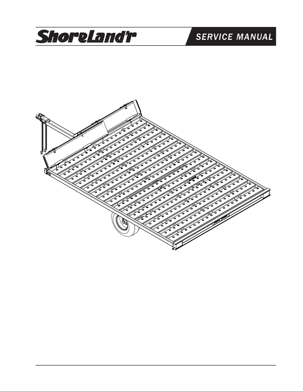
2-Place ATV Trailer
2-Place ATV Trailer w/13” Tires
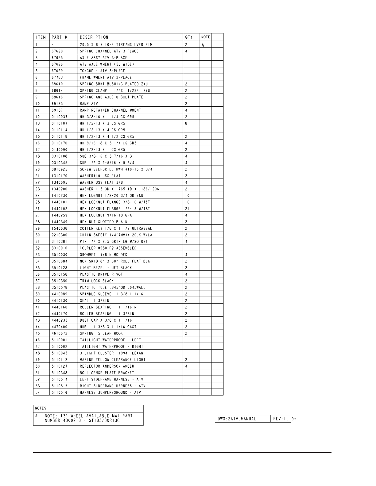
Bundles Required - 2ATV
*20.5x8x10E Tire/Rim
65069 Lit Packet - SL Utility
6778503 Frame Bundle ATV - 2 Place
*Check with your dealer/customer service representative for current tire/rim assembly
part number.
Midwest Industries, Inc. Ida Grove, IA 51445 800.859.3028 www.shorelandr.com 0003164
Page 1 REV C 02/20/06
Bundles Required - 2ATVA
*
65069 Lit Packet - SL Utility
6778503 Frame Bundle ATV - 2 Place
*Check with your dealer/customer service representative for current tire/rim assembly
part number.
ST185/80R13C Tire/Dir Rim
Page 2
Midwest Industries, Inc. Ida Grove, IA 51445 800.859.3028 www.shorelandr.com 0003164
Page 2 REV C 02/20/06
Page 3

Midwest Industries, Inc. Ida Grove, IA 51445 800.859.3028 www.shorelandr.com 0003164
Page 3 REV C 02/20/06
Page 4

Midwest Industries, Inc. Ida Grove, IA 51445 800.859.3028 www.shorelandr.com 0003164
Page 4 REV C 02/20/06
Page 5

2ATV / 2ATVA Assembly Instructions:
Cut all banding and sort hardware bags.
L a y t h e 2 AT V o r 2 AT VA o n t h e s a w h o r s e s
(recommendation) to assemble.
Raise the axle assembly up under the leaf springs and align
the pin on the bottom side of the spring with the hole in the
axle. Align the holes in a spring plate with the legs of the Ubolts just placed around the springs. Slide the spring plate
onto the U-bolts and secure with 1/2” flange lock nuts. Repeat
on the second spring on the opposite side of the trailer.
Run tongue wire harness through the tongue and plug into
the side frame harnesses on the frame.
Slide the tongue into the two (2) tongue channel on the frame
and secure with two (2) 1/2” X 4-1/2” hex bolts and two (2)
1/2” flange lock nuts.
Plug the tongue wire harness into the side frame harnesses
on the frame. The white ground wire must be attached to the
frame by placing a self-tapping screw into the round ring on
the white ground wire of the tongue harness, then drilling into
the trailer frame tube member.
See Detail B.
Insert a 3/8” X 1-1/4” hex bolt with a 3/8” flat washer and
safety chain through the lower hole on the front of the tongue.
Secure with a 3/8” flat washer and 3/8” flange lock nut.
Repeat assembly on opposite side of the tongue.
Mount the coupler to the tongue using two (2) 1/2” X 1” hex
bolts in the front holes and one (1) 1/2” X 4” hex bolt in the
rear hole of the coupler. Secure the 1/2” flange lock nuts.
AXLE ASSEMBLY:
Remove the spring channels from the axle. Attach the spring
channels to the side frame using 1/2” X 3” hex bolts and
secure with 1/2” flange lock nuts.
Place the other 1/2” X 3” hex bolt into the spring channel and
through the frame. Secure with 1/2” flange lock nuts.
NOTE:
10” Tire - Top hole on spring channel
13” Tire - Bottom hole on spring channel
In the rear spring channel place the spring bracket bushing
(Ref.#7) into specific hole location, refer to the NOTE for
placement depending on tire size. Secure the spring bracket
bushing to the spring channel using a 9/16” X 3-1/4” hex bolt
and 9/16” hex bolt.
Slide the hook end of the spring over the spring bracket
bushing just installed.
Mount the other end of the spring to the spring channel using
a 9/16” X 3-1/4” hex bolt and secure with a 9/16” hex nut. Do
not over tighten.
Mount the axle assembly to the leaf spring using two (2) 1/2”
X 2-5/16” X 5-3/4” u-bolts, one (1) spring clamp and one (1)
spring plate. Secure with 1/2” flange lock nuts. Refer to the
Detail A for placement. Repeat on opposite side of the axle
assembly.
Remove the stud thread protectors. Mount the tires to the
hubs using 1/2” lug nuts. Note the taper end of the nut must
be towards the rim. Hand tighten the lug nuts using the star
pattern as described in the owners guide. Use a torque wrench
for the final tightening of the lug nuts. Torque to 85-95 ft. lbs.
of torque. Recheck the torque after 50 miles of use, then
periodically thereafter.
Installing the Ramps and the
Retainer Attachment Channels
Installing the ramps in the following manner will allow for the
removal of the ramp from the drivers side of the trailer first.
Locate the four ramp retainer attachment channels. Note
that they are all identical.The two ramp retainer attachment
channels on the right side of the trailer will be installed on the
front side of the trailer front frame tube to support the ramp
as shown in Detail D.
Install the other two ramp retainer attachment channels on
the left side of the trailer to the rear of the front frame tube as
shown in Detail E. This will allow the ramps to overlap past
each other in the middle.
Place a 3/8” x 3 7/8” x 3” square U-bolt around the front frame
tube so the legs of the U-bolt are pointing forward. Align the
holes in one of the ramp retainer attachment channels with
the U-bolt legs, then slide into position. Note that this channel is mounted on the front side of the frame tube. Secure in
place with 3/8” hex flange lock nuts. Position the U-bolt so it
is 10 ½” from the outside of the side frame tube as shown on
page 3. Tighten in position. Repeat this process on a second
channel. Position this ramp retainer attachment channel so
that the center hole in the bracket is 27” from the center hole
in the ramp retainer attachment channel just installed. Tighten
enough only to hold in position until the ramp is installed.
Place a 3/8” x 3 7/8” x 3” square U-bolt around the front frame
tube so the legs of the U-bolt are pointing backward. See
Detail E. Align the holes in one of the ramp retainer attachment channels with the U-bolt legs, then slide into position.
Note that this channel is on the rear side of the frame tube
as shown in Detail E. Secure in place with 3/8” hex flange
lock nuts. Position the U-bolt so it is 10 ½” from the outside
of the side frame tube as described above for the opposite
side of the trailer. Tighten in position. Repeat this process
on a second channel. Position this ramp retainer attachment
channel so that the center hole in the bracket is 27” from
the center hole in the ramp retainer attachment channel just
installed. Tighten enough only to hold in position until the
ramp is installed.
Once all four of the ramp retainer attachment channels are
attached to the frame, position the right ramp in the ramp
retainer attachment channels. The ramp can either be slid
Midwest Industries, Inc. Ida Grove, IA 51445 800.859.3028 www.shorelandr.com 0003164
Page 5 REV C 02/20/06
Page 6

into the end of the channels or else placed in the approximate
position, then rotated into place. The right-hand ramp must
always be installed first.
See Detail D. Align the holes provided in the edge of the
ramp with the holes in the center of the ramp retainer attachment channels as follows: Place one of the ¼” pins with
wire retainer through the aligned holes in the ramp and the
retainer attachment channel positioned 10 ½” from the side
of the frame and secure.
Align the hole in the second ramp retainer attachment channel
with the second hole in the ramp. Note that the U-bolt may
have to be loosened so the ramp retainer can be moved either
direction to align the holes. When aligned, insert a second ¼”
pin with wire retainer. Once the pin is inserted, retighten the
U-bolt loosened to adjust for proper hole spacing. The two
pins will secure the ramps in the transport position.
Repeat this process on the second ramp.
CAUTION:
To prevent damage to your ATV trailer, tighten all fasteners
before towing.
Your ATV trailer is equipped with a totally grounded wire
harness. You must be sure the wire harness plug that comes
from the tow vehicle is grounded to the tow vehicle using the
white grounding wire.
Always secure (tie) your load down before towing.
Check all lights for proper operation before towing.
Check all lug nuts for proper torque before towing.
Midwest Industries, Inc. Ida Grove, IA 51445 800.859.3028 www.shorelandr.com 0003164
Page 6 REV C 02/20/06
 Loading...