

Page 1
p
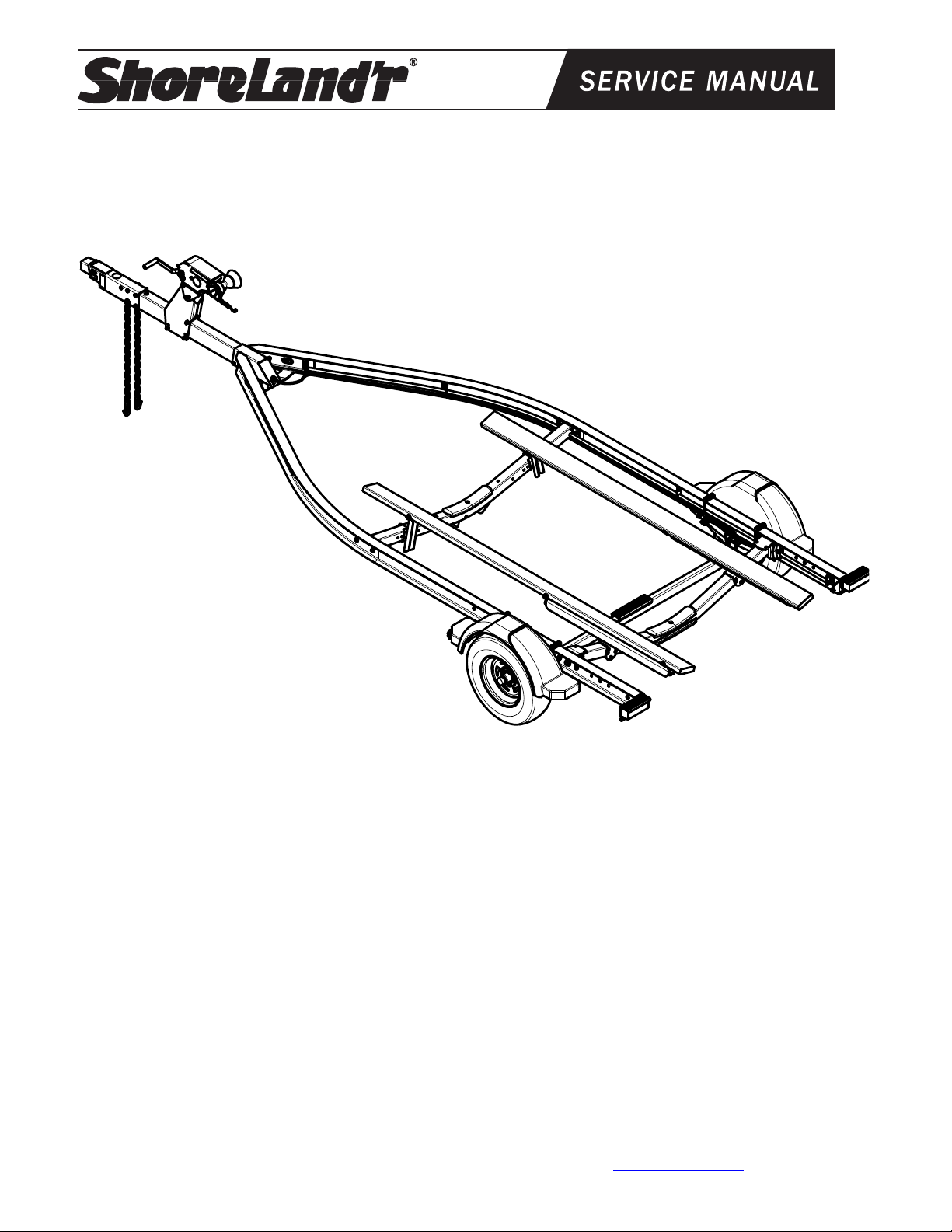
3000# Aluminum Fully Grounded Bunk Trailer
SLB30BAL
SLB30BAL Bundles
* ST215/75R14C Tire/Galv Dir
69082 Lit Packet Brake Trailer
7085300 Tongue Assy 55” S.S. Disc FG
8081800 Frame Bundle SLB30BAL FG
*Check with your dealer/customer service representative for current
tire/rim assembly part number.
IMPORTANT: All hardware for your trailer is stainless steel. It is important that you use
an anti-seize material on the bolt threads when assembling to prevent gauling.
Tire Size: ST215/75R 14-C
GVWR: 3740 lb.
Carrying Capacity: 3000 lbs.
Axle: Brake
Refer to the tire side wall for correct tire
ressure.
Midwest Industries, Inc. Ida Grove, IA 51445 800-859-3028 www.shorelandr.com 0004296
Page 1 of 12 2/2/2011
Page 2
Midwest Industries, Inc. Ida Grove, IA 51445 800-859-3028 www.shorelandr.com 0004296
Midwest Industries, Inc. Ida Grove, IA 51445 800-859-3028 www.shorelandr.com 0004296
Page 2 of 12 2/02/2011
Page 2 of 12 2/02/2011
Page 3

Midwest Industries, Inc. Ida Grove, IA 51445 800-859-3028 www.shorelandr.com 0004296
Page 3 of 12 2/02/2011
Page 4
Midwest Industries, Inc. Ida Grove, IA 51445 800-859-3028 www.shorelandr.com 0004296
Midwest Industries, Inc. Ida Grove, IA 51445 800-859-3028 www.shorelandr.com 0004296
Page 4 of 12 2/02/2011
Page 4 of 12 2/02/2011
Page 5

Midwest Industries, Inc. Ida Grove, IA 51445 800-859-3028 www.shorelandr.com 0004296
Page 5 of 12 2/02/2011
Page 6

Midwest Industries, Inc. Ida Grove, IA 51445 800-859-3028 www.shorelandr.com 0004296
Page 6 of 12 2/02/2011
Page 7

Midwest Industries, Inc. Ida Grove, IA 51445 800-859-3028 www.shorelandr.com 0004296
Page 7 of 12 2/02/2011
Page 8

Midwest Industries, Inc. Ida Grove, IA 51445 800-859-3028 www.shorelandr.com 0004296
Page 8 of 12 2/02/2011
Page 9

Midwest Industries, Inc. Ida Grove, IA 51445 800-859-3028 www.shorelandr.com 0004296
Page 9 of 12 2/02/2011
Page 10

Midwest Industries, Inc. Ida Grove, IA 51445 800-859-3028 www.shorelandr.com 0004296
Page 10 of 12 2/02/2011
Page 11

Midwest Industries, Inc. Ida Grove, IA 51445 800-859-3028 www.shorelandr.com 0004296
Page 11 of 12 2/02/2011
Page 12

TRAILER ADJUSTMENTS
Axle Adjustment
The amount of tongue weight on your trailer can be adjusted as follows: To lower the tongue weight,
adjust the axle assembly forward. To increase the tongue weight, adjust the axle assembly backward.
The distance that the axle assembly has to be moved will vary because it is directly related to the
weight and center of gravity of the boat place on it. Best towing is achieved when the tongue weight is
5-7% of the total gross load of the complete unit.
NOTE: Brake line and wire harness will need care when moving the assembly.
Rear Support System
Place the boat on the trailer so that the transom is located at the rear of the support system. On a bunk
trailer, the transom of the boat should be within 1-2” of the end of the bunk. This gives you maximum
support on the transom.
The rear cross member is adjustable forward or backward to allow the trailer to be adjusted to various
length boats. This is accomplished by removing the pivot bolt on each end that holds the rear pivot arm
to the side frame and the rear pivot offset weldments.
Once the rear pivot arm assembly is removed, remove the two additional bolts on each side frame that
mount the rear pivot offset weldments to the side frame. Move them to the desired location and
remount to the side frames with the bolts just removed. Reposition the rear pivot arm between the two
rear pivot offset weldments just installed. Secure in place using the two pivot bolts removed earlier.
Tighten. The wire harness for the three-light identification light must be re-positioned where it comes
from the black wire harness tubing to eliminate slack, and sagging of the wiring.
Bunks
The bunks must be positioned far enough apart to give your boat as much stability as possible while
transporting. Position the bunks so they are located just to the outside of the boat’s strake. This will
help center your boat and assist when loading. The bunks need to be adjusted up high enough to keep
the keel from resting on the center pads. A minimum of 1” to 2” of clearance is desirable.
Winch Post/Bow-eye
Slide the winch post base backward on the tongue until the bow roller comes in contact with the boat.
The bow roller needs to be positioned directly above the boat bow eye to prevent your boat from
moving forward in the event of a sudden stop. It can be moved up or down by removing the back bolt
that mounts the winch head to the base. When this bolt is removed, the head can be rotated up or
down to reach the height required to fit your boat. Once in this position, align the closest pair of holes in
the brackets and reinsert the bolt just removed. Tighten. Attach the winch strap and crank winch tight.
Attach the bow eye safety chain into the bow eye of the boat as well. This is just another level of
protection to keep your boat and trailer together as one unit.
Adjustments are now complete.
Double check your boat for fit. If desired fit has been achieved, tighten all fasteners that may have
either been left loose or have been loosened to do the adjusting.
Re-check all fasteners on the complete trailer to make sure they are all tight and ready for towing. All
fasteners should be periodically checked before towing.
See your ShoreLand’r Owner’s Guide for further technical information regarding your trailer and its
components.
Midwest Industries, Inc. Ida Grove, IA 51445 800-859-3028 www.shorelandr.com 0004296
Page 12 of 12 2/02/2011
 Loading...