

Shop-Vac 87P series, 92P series, 90P series User Manual

ATTENTION!
Read all safety rules carefully
before attempting to operate.
Retain for future reference.
ATTENTION!
Lisez attentivement les instructions sur la sécurité
avant d’utiliser cet appareil.
Conservez cette Notice pour
vous y reporter ultérieurement.
¡
ATENCIÓN!
Lea cuidadosamente todas
las normas de seguridad
antes de utilizar la aspiradora. Conserve esta manual para consultas futuras.
DANGER!
Never operate this unit when
flammable materials or vapors
are present because electrical devices produce arcs or
sparks that can cause a fire
or explosion.
NEVER OPERATE
UNATTENDED!
User manual
Please review before operating vac.
Manuel d’utilisation
Veuillez lire avant d’utiliser l’aspirateur.
Manual del usuario
Por favor lea esta manual antes de usar la aspiradora.
BRAND/MARQUE/MARCA
Wet/Dry Vacuum
Household and Workshop Use
Series 87P, 90P, 92P
Aspirateur pour déchets secs et humides
Pour utilisation domestique ou dans les entrepôts
Série 87P, 90P, 92P
Aspiradora para aspiración de residuos
Líquidos/Sólidos
Para Uso Doméstico y Comercial
DANGER
N’utilisez jamais cet aspirateur en présence de vapeurs
ou de matières inflammables.
Les appareils électriques
produisent des arcs ou des
étincelles qui peuvent causer
un incendie ou une explosion.
!
NE JAMAIS FAIRE
FONCTIONNER SANS
SURVEILLANCE!
¡
PELIGRO!
Nunca opere esta unidad ante
la presencia de materiales o
vapores inflamables dado que
los artefactos eléctricos producen arcos o chispas que
pueden causar un incendio o
una explosión.
¡
NO DEJE LA ASPIRADORA FUNCIONANDO SIN VIGILANCIA!
Serie 87P, 90P, 92P
SHOP-VAC CORPORATION
2323 Reach Road, P.O. Box 3307
Williamsport, PA 17701-0307
(570) 326-3557
www.shopvac.com
SHOP-VAC CANADA
1770 Appleby Line
Burlington, Ontario L7L 5P8
(905) 335-9730
www.shopvac.ca
Shop Vac-México, S.A. de C.V.
Av. Mariano Otero #5095, Local 1 PB
Col. La Calma
Zapopan, Jalisco C.P. 45070
MÉXICO
52 (33) 3188 6388
Patents Issued and Pending.
Brevets délivrés et en instance.
Patentes registradas y en trámite.
© 2012 Shop-Vac Corporation. All Rights Reserved.
© Shop-Vac Corporation, 2012. Tous droits réservés.
© 2012 Shop-Vac Corporation. Todos los derechos reservados. 87547-36
IMPORTANT SAFETY INSTRUCTIONS
When using an electrical appliance, basic precautions should always be followed, including the
following: READ ALL INSTRUCTIONS BEFORE USING THIS APPLIANCE.
WARNING – TO REDUCE THE RISK OF FIRE, ELECTRIC
SHOCK OR INJURY:
1. Do not leave appliance when plugged in. Unplug from outlet when not in use and before
servicing. Connect to a properly grounded outlet only. See Grounding Instructions.
2. Do not expose to rain – store indoors.
3. Do not allow to be used as a toy. Close attention is necessary when used by or near children.
4. Use only as described in this manual. Use only Manufacturer’s recommended attachments.
5. Do not use with damaged cord or plug. If appliance is not working as it should, has been
dropped, damaged, left outdoors or dropped into water, contact Shop-Vac Corporation for
assistance.
6. Do Not: pull or carry by cord, use cord as a handle, close a door on cord or pull cord around
sharp edges or corners. Do not run appliance over cord. Keep cord away from heated surfaces.
7. Do not unplug by pulling on cord. To unplug, grasp the plug, not the cord.
8. Do not handle plug or appliance with wet hands.
9. Do not put any object into openings. Do not use with any openings blocked; keep free of dust,
lint, hair and anything that may reduce air flow.
10. Keep hair, loose clothing, fingers and all parts of body away from openings and moving parts.
11. Do not pick up anything that is burning or smoking, such as cigarettes, matches or hot ashes.
12. Do not use without dust bag and/or filters in place.
13. Turn off all controls before unplugging.
SAVE THESE INSTRUCTIONS
14. Use extra care when cleaning on stairs.
15. Do not use to pick up flammable or combustible liquids such as gasoline or use in areas where
they may be present.
16. Do not use your cleaner as a sprayer of flammable liquids such as oil base paints, lacquers,
household cleaners, etc.
17. Do not vacuum toxic, carcinogenic, combustible or other hazardous materials such as
asbestos, arsenic, barium, beryllium, lead, pesticides or other health endangering materials.
Specially designed units are available for these purposes.
18. Do not pick up soot, cement, plaster or drywall dust without cartridge filter and collection
filter bag in place. These are very fine particles that may pass through the foam and affect the
performance of the motor or be exhausted back into the air. Additional collection filter bags are
available.
19. Do not leave the cord lying on the floor once you have finished the cleaning job. It can become
a tripping hazard.
20. Use special care when emptying heavily loaded tanks.
21. To avoid spontaneous combustion, empty tank after each use.
22. The operation of a utility vac can result in foreign objects being blown into eyes, which can
result in eye damage. Always wear safety goggles when operating vacuum.
23. STAY ALERT. Watch what you are doing and use common sense. Do not use vacuum cleaner
when you are tired, distracted or under the influence of drugs, alcohol or medication causing
diminished control.
24. WARNING! Do NOT use this vacuum cleaner to vacuum lead paint debris because this may
disperse fine lead particles into the air. This vacuum cleaner is not intended for use under EPA
Regulation 40 CFR Part 745 for lead paint material cleanup.
WARNING
– DO NOT LEAVE VACUUM UNATTENDED WHEN IT IS PLUGGED IN AND/OR OPERATING. UNPLUG UNIT WHEN NOT IN USE.
GROUNDING INSTRUCTIONS
This appliance must be grounded. If it should malfunction or breakdown, grounding provides
a path of least resistance for electric current to reduce the risk of electric shock. This appliance is equipped with a cord having an equipment-grounding conductor and grounding plug.
The plug must be inserted into an appropriate outlet that is properly installed and grounded in
accordance with all local codes and ordinances.
WARNING – IMPROPER CONNECTION OF THE EQUIP-
MENT-GROUNDING CONDUCTOR CAN RESULT IN A RISK OF ELECTRIC
SHOCK. CHECK WITH A QUALIFIED ELECTRICIAN OR SERVICE PERSON IF YOU ARE IN DOUBT AS TO WHETHER THE OUTLET IS PROPERLY GROUNDED. DO NOT MODIFY THE PLUG PROVIDED WITH THE
APPLIANCE – IF IT WILL NOT FIT THE OUTLET, HAVE A PROPER OUTLET
INSTALLED BY A QUALIFIED ELECTRICIAN.
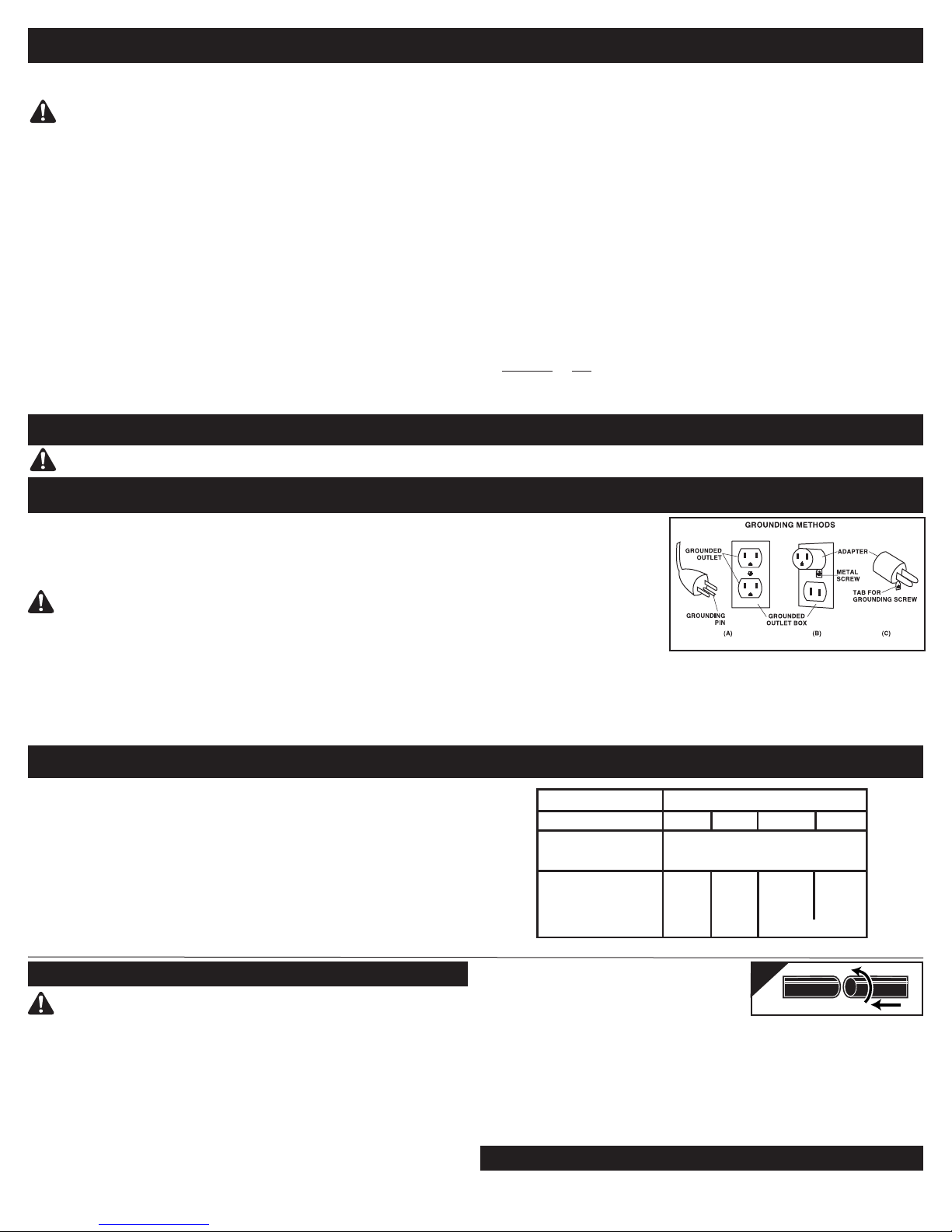
This appliance is for use on a nominal 120-volt circuit, and has a grounded plug that looks
like the plug illustrated in sketch A. A temporary adaptor that looks like the adaptor illus-
EXTENSION CORDS
When using the appliance at a distance where an extension cord becomes necessary, a 3-conductor
grounding cord of adequate size must be used for safety, and to prevent loss of power and overheating. Use the table below to determine A.W.G. wire size required. To determine ampere rating of your
vacuum, refer to nameplate located on rear of motor cover. Before using appliance, inspect power
cord for loose or exposed wires and damaged insulation. Make any needed repairs or replacements
before using your appliance. Use only three-wire outdoor extension cords which have three-prong
grounding-type plugs and three-pole receptacles which accept the extension cord’s plug. When
vacuuming liquids, be sure the extension cord connection does not come in contact with the liquid.
NOTE: STATIC SHOCKS ARE COMMON IN DRY AREAS OR WHEN THE RELATIVE HUMIDITY OF THE AIR
IS LOW. THIS IS ONLY TEMPORARY AND DOES NOT AFFECT THE USE OF THE APPLIANCE. TO REDUCE
THE FREQUENCY OF STATIC SHOCKS IN YOUR HOME, THE BEST REMEDY IS TO ADD MOISTURE TO
THE AIR WITH A CONSOLE OR INSTALLED HUMIDIFIER.
UNPACKING AND SET-UP
WARNING – ALWAYS DISCONNECT THE PLUG FROM THE
WALL OUTLET BEFORE REMOVING THE TANK COVER.
1. Pull lid latches in an outward motion and remove tank cover. Remove any accessories,
which may have been shipped in the tank.
2. Attach caster system following the instructions and illustrations in this manual.
3. Before replacing tank cover ensure you have the proper filters installed for your cleaning
operation.
A. For dry pick up refer to Dry Pick Up Operation.
B. For wet pick up refer to Wet Pick Up Operation.
C. When using the pump operation feature refer to Pump Operation.
4. Make sure inlet deflector is fully inserted into deflector guide on inside of tank. (See
Installing the Cartridge Filter)
5. Replace tank cover and apply pressure with thumbs to each latch until it snaps tightly in
place. Make sure both lid latches are clamped securely.
trated in sketches B and C may be
used to connect this plug to a 2-pole
receptacle as shown in sketch B
if a properly grounded outlet is not
available. The temporary adaptor
should be used only until a properly
grounded outlet (sketch A) can be
installed by a qualified electrician.
The green colored rigid ear, lug or
the like extending from the adaptor
must be connected to a permanent
ground such as a properly grounded outlet box cover. Whenever the adaptor is used, it must be
held in place by a metal screw.
IN CANADA, THE USE OF A TEMPORARY ADAPTOR IS NOT PERMITTED BY THE CANADIAN
ELECTRICAL CODE. Make sure that the appliance is connected to an outlet having the same
configuration as the plug. No adapter should be used with this appliance.
Volts
120V
Ampere Rating
More Not More
Than Than
0 - 6
6 - 10
10 - 12
12 - 16
6. Insert long machine hose end with locking-nut into
inlet of tank and tighten. Do not over-tighten.
7. Attach ergonomic elbow grip to accessory end
of hose for a more comfortable hand grip while
vacuuming. Twist slightly to tighten the connection
(Figure 1).
8. Attach the extension wands to the ergonomic elbow grip. Twist slightly to tighten the connection (Figure 1).
9. Attach one of the cleaning accessories (depending on your cleaning requirements) to the
extension wands. Twist slightly to tighten the connection (Figure 1).
10. Plug the cord into the wall outlet. Your cleaner is ready for use. I = ON, O = OFF
NOTE: MANY MORE USEFUL TOOLS ARE AVAILABLE AT YOUR LOCAL DEALER OR SHOP-VAC
WEBSITE.
Total length of cord in feet
25 50 100
150
AWG
18
18
16
14
16
16
16
12
16
14
14
Not recommended
1
14
12
12
CASTER SYSTEM ASSEMBLY
Not all units are equipped with the same caster system. Follow the instructions,
which apply to your specific unit.
®
A
A
A
A
A
A
B
B
B
B
B
B
A
A
B
B
B
B
B
B
B
A
A
A
A
A
A
A
A
A
A
B
A
B
Screw
Sealing
Washer
Hex Head
Locknut
Carriage
Handle
Without Caster Feet
You will find four casters (Figure 2) with your wet/dry
2
3
vacuum. Assemble as follows:
1. With cord disconnected from receptacle and tank
cover removed, turn tank upside down so that bottom
is facing up.
2. Insert casters into bottom of tank by placing stem of caster into holes provided. Apply pressure and twisting motion until casters snap into place (Figure 3).
3. Return tank to upright position.
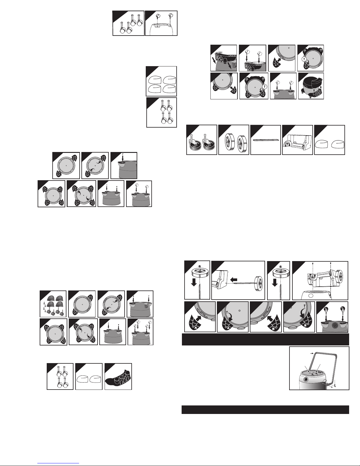
5-8 U.S. Gallons (18.9 - 30.2L) With Caster Feet
You will find four caster feet (Figure 4), four casters (Figure 5), and four
screws with your wet/dry vacuum. Assemble as follows:
4
1. With cord disconnected from receptacle and tank cover removed, turn
tank upside down so that bottom is facing up.
2. Remove any webbing that attaches the caster feet to each other.
3. With front of tank inlet facing you, take caster feet marked with the letter
A (Figure 6) and insert stem of caster foot into holes on left front and
right rear of tank also marked with letter A (Figure 7). Make sure caster
5
feet are fully inserted into tank bottom and secure with screws provided
(Figure 8).
4. Take caster feet marked with the letter B (Figure 9) and insert stem of
caster foot into holes on right front and left rear of tank also marked
with the letter B (Figure 10). Make sure caster feet are fully inserted
into tank bottom and secure with screws provided (Figure 11).
5. Insert casters into feet by placing stem of caster into holes provided. Apply pressure and
twisting motion until casters snap into place (Figure 12).
6. Return tank to upright position.
10
7
11
8
12
6
9
10 U.S. Gallons (37.8L) and Up With Caster Feet
You will find four caster feet, four casters and four screws (Figure 13) with your wet/dry
vacuum. Assemble as follows:
1. With cord disconnected from receptacle and tank cover removed, turn tank upside down so
that bottom is facing up.
2. With front of tank facing you, take caster feet marked with the letter A (Figure 14) and
place in slots on left front and right rear of tank also marked with the letter A (Figure 15).
Secure with screws provided (Figure 16).
3. Take caster feet marked with the letter B (Figure 17) and place in slots on right front and
left rear of tank also marked with the letter B (Figure 18). Secure with screws provided
(Figure 19).
4. If flat washers are included in hardware package place flat washer over stem of caster
before installing casters into feet. NOTE: Flat washers are not required with all units.
5. Insert casters into feet by placing stem of caster into holes provided. Apply pressure and
twisting motion until casters snap into place (Figure 20). Return tank to upright position.
13
14
15
16
B
also marked with the letter B. Secure with screw provided (Figure 29).
7. Insert casters into feet by placing stem of casters into holes provided. Apply pressure and
twisting motion until casters snap into place (Figure 30).
8. Return tank to upright position.
9. Place tool basket (not standard with all models) with curved surface against tank on rear
caster dolly assembly (Figure 31).
24
28
25
29
26
30
27
A
31
With Rear Wheel Dolly
You will find two casters (Figure 32), two large rear wheels (Figure 33), one axle (Figure 34), rear dolly/
basket (Figure 35), two caster feet (Figure 36) and four screws with your wet/dry vacuum. Assemble
as follows:
32
33
34 35 36
1. With cord disconnected from receptacle and tank cover removed, turn tank upside down so that the
bottom is facing up.
2. Place axle upright on a hard surface and hammer on (1) cap nut. Place (1) wheel on axle and slide
down to cap nut (Figure 37). Be sure flat side of wheel hub is facing outward.
3. Slide axle through holes provided in dolly/basket (Figure 38).
4. Slide remaining wheel onto axle and hammer on second cap nut (Figure 39).
5. Take rear dolly assembly and place into slots (on rear of tank opposite drain) and secure with
screws provided (Figure 40).
6. With tank drain facing you, take caster foot marked with the letter A (Figure 41) and place in
slot on left side of tank also marked with the letter A and secure with screw provided (Figure
42).
7. Take caster foot marked with the letter B (Figure 43) and place in slot on right side of tank
also marked with the letter B and secure with screw provided (Figure 44).
8. Insert casters into feet by placing stem of caster into holes provided. Apply pressure and
twisting motion until casters snap into place (Figure 45).
9. Return tank to upright position.
37
41
38
39 40
42 43 44
45
17
18
19
20
With Rear Caster Dolly/Tool Holder
You will find four casters (Figure 21), two caster feet (Figure 22), rear caster dolly/tool holder
(Figure 23), and four screws with your wet/dry vacuum. Assemble as follows:
21
22
23
1. With cord disconnected from receptacle and tank cover removed, turn tank upside down so
that the bottom is facing up.
2. Take rear caster dolly and place into slots (on rear of tank, opposite of drain) and secure
with screws provided (Figure 24).
3. If flat washers are included in hardware package place flat washer over stem of caster
before installing casters into feet. NOTE: Flat washers are not required with all units.
4. Insert casters into bottom of rear caster dolly by placing stem of caster into holes provided.
Apply pressure and twisting motion until casters snap into place (Figure 25).
5. With tank drain facing you, take caster foot marked with the letter A (Figure 26) and
6. Take caster foot marked with the letter B (Figure 28) and place in slot on right side of tank
place in slot on left side of tank also marked with the letter A. Secure with screw provided
(Figure 27).
INSTALLING THE CARRIAGE HANDLE
(Not standard with all models)
Stand vacuum right side up. Place metal carriage handle
outside of tank and under the side carrying handles. Be sure
to spread the ends of the carriage handles when assembling
to prevent damage to the tank. Align holes of carriage
handle to holes in tank and fasten tightly with screws,
washers, and nuts provided. The sealing washer and screw
have a close fitting tolerance. Rubber side of sealing washer
should fit against inside wall of tank. Failure to properly
install rubber washer could result in water leakage or loss of performance. Replace the tank
cover and clamp the lid latches securely.
TOOL HOLDER
(Not standard with all models)
If your tool holder looks like the one pictured in Figure 46, follow these instructions.
1. With rear of unit facing you, take tool holder and position it with tabs facing rear of unit
(Figure 47).
2. Place “J” shaped tabs into the slots on cord wraps (Figure 48).
3. Press down until tabs snap into place.
4. Press down on center of tool holder until tab latches on bottom lid (Figure 49).
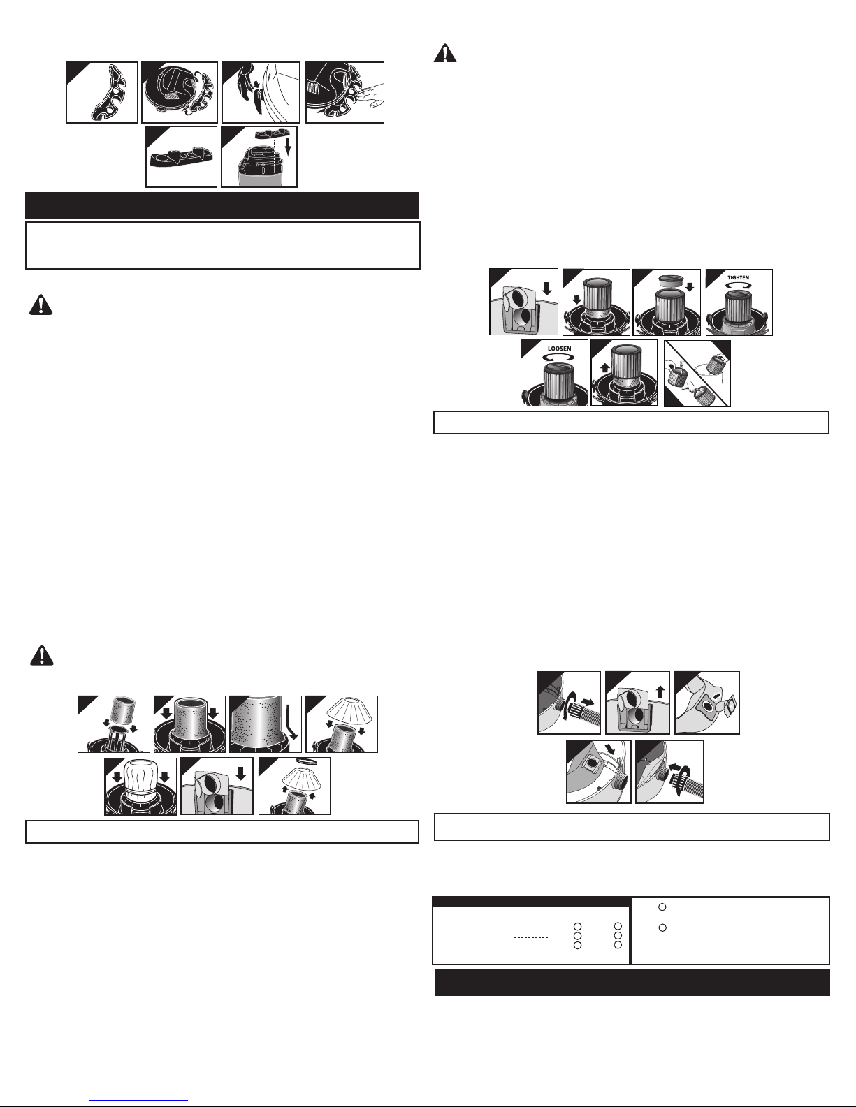
If your tool holder looks like the one pictured in Figure 50, follow these instructions.
1. With rear of unit facing you, take tool holder and slide over notches on rear of tank (Figure
51).
46
47
50
48
51
49
DRY PICK UP OPERATION
INSTALLING FOAM SLEEVE AND REUSABLE
DRY FILTER
(Not standard with all units)
WARNING – ALWAYS DISCONNECT THE PLUG FROM
THE WALL OUTLET BEFORE REMOVING THE TANK COVER.
1. The foam sleeve and reusable dry filter may be used to pick up dust and dry material; you
must install both to insure proper filtration. If the vacuum has been used to pick up liquids,
the foam sleeve must be cleaned and dried before installing for dry pick up. (See Wet Pick
Up Operation on how to clean foam sleeve).
2. With tank cover in an upside down position, slide foam sleeve down over lid cage pulling
until foam sleeve completely covers lid cage (Figure 52). Foam sleeve must be positioned
on the OUTSIDE of groove around lid cage for the reusable dry filter to fit properly (Figure
53, 54).
3. Center the reusable dry filter on bottom of lid cage (Figure 55), slide mounting ring over
filter until ring is positioned against the top of the lid cage (Figure 56).
NOTE: ENSURE THAT THE MOUNTING RING IS COMPLETELY SECURE AND IN POSITION BY
PRESSING DOWN FIRMLY AROUND THE RING IN SEVERAL PLACES. BE SURE THE REUSABLE
DRY DISC FILTER COMPLETELY COVERS THE FOAM SLEEVE. CHECK TO ENSURE THAT ALL
EDGES OF THE REUSABLE DRY FILTER ARE SECURE UNDER THE MOUNTING RING.
4. Make sure inlet deflector is fully inserted into deflector guide on inside of tank. If it is not,
install inlet deflector by sliding it downward into slot on deflector guide (Figure 57). NOTE:
Hose must be removed before inlet deflector can be inserted into or removed from deflector
guide. Opening on inlet deflector can face either side of tank. Inlet deflector should always
be in place for any type of cleaning.
5. To clean the reusable dry filter
a. Remove mounting ring and filter from lid cage (Figure 58).
b. Shake off excess dirt and dust or (depending on the condition of the filter) rinse with
water. DO NOT MACHINE WASH OR DRY.
c. To clean foam sleeve refer to Wet Pick Up Operation in this manual.
d. Allow filters to dry completely before reinstalling.
CAUTION – KEEP FILTERS CLEAN
IMPORTANT: BEFORE INSTALLING FILTER BE SURE THAT FOAM SLEEVE IS OUTSIDE OF
GROOVE AROUND LID CAGE (Figure 53, 54).
52 53
54
55
Wet Pick Up:
WARNING – THE CARTRIDGE FILTER IS NOT COMPATIBLE
WHEN UTILIZING THE PUMP PICK UP ASSEMBLY.
1. The cartridge filter can be used for wet pick up. However, when picking up large quantities
of water containing debris we recommend using the foam sleeve (not standard with all
models). (See the Wet Pick Up Operation section for foam sleeve installation).
2.
Make sure inlet deflector is fully inserted into deflector guide on inside of tank. If it is not,
install inlet deflector by sliding it downward into slot on deflector guide (Figure 59). NOTE:
Hose must be removed before inlet deflector can be inserted into or removed from deflector
guide. Opening on inlet deflector can face either side of tank. Inlet deflector should always be
in place for any type of cleaning.
3. Installation for wet pick up is the same as for dry pick up. Follow steps 3 and 4 under Dry
Pick Up (Installing the cartridge filter).
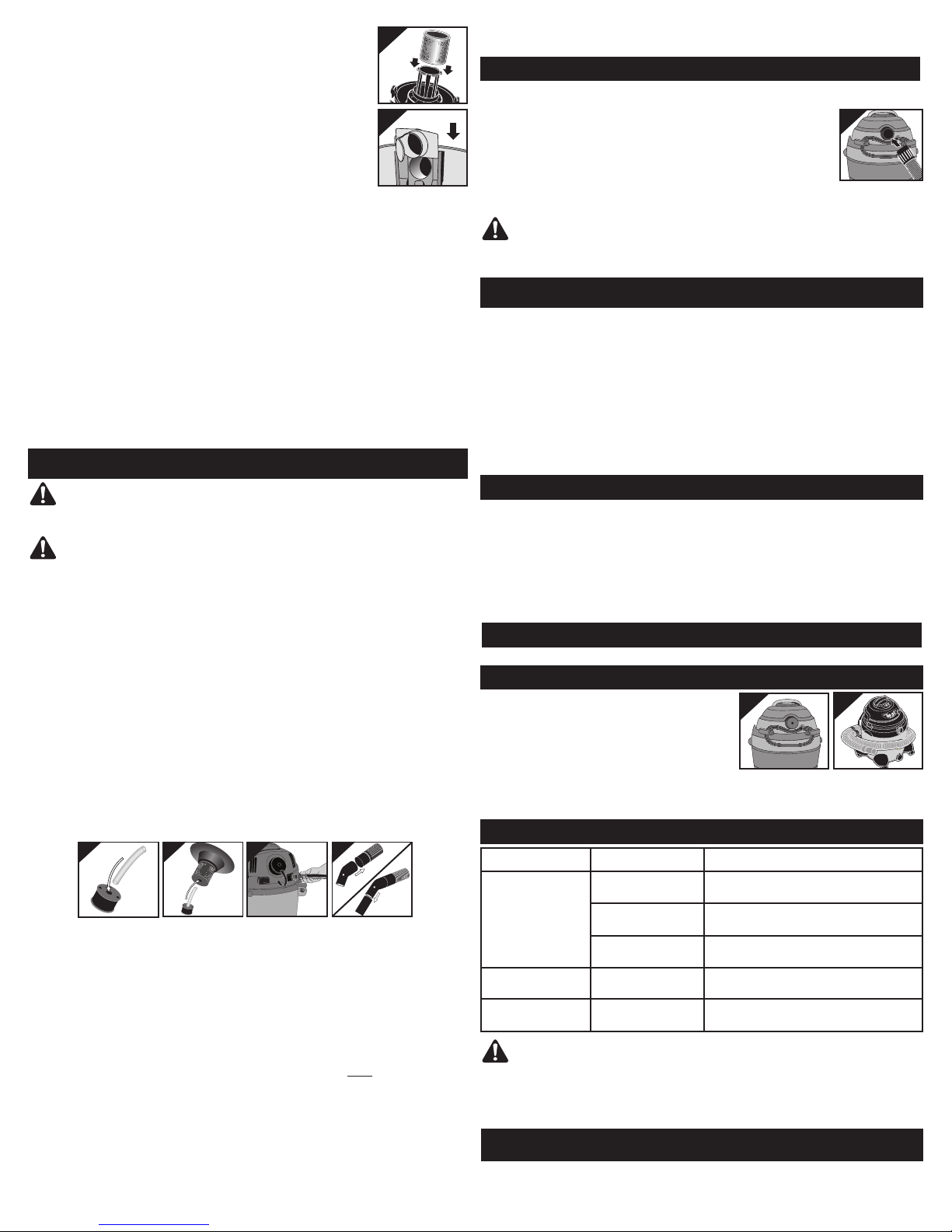
Cleaning:
1. Remove filter by holding the tank cover while turning the filter retainer counter-clockwise to
loosen and remove. Slide filter off the lid cage (Figures 63 & 64).
2. Clean cartridge filter by shaking or brushing off excess dirt or rinse (from the inside of the
filter) with water, dry completely (approximately 24 hours) and reinstall (Figures 65 & 66).
59 60
63
64
INSTALLING THE DISPOSABLE FILTER BAG
(Not Standard with All Models)
1. Use for dry pick up only. Use in conjunction with cartridge filter for picking up soot, cement,
plaster or drywall dust.
2. With cord disconnected from receptacle, pull latches in an outward motion and remove tank
cover.
3. Unscrew hose locking-nut and remove hose from inlet (Figure 67).
4. Remove inlet deflector from deflector guide (Figure 68). NOTE: Hose must be removed
before inlet deflector can be taken out.
5. With the opening of the inlet deflector facing the left or right side of the filter bag, slide filter
bag collar over deflector matching notches of bag collar to tabs on inlet deflector, bag will
only fit properly one way (Figure 69).
6. Slide deflector with collection bag attached into deflector guide (Figure 70).
7. Reinsert hose into inlet and tighten locking-nut (Figure 71).
8. When secured in place, expand bag and position around the inside of tank.
9. Replace tank cover.
NOTE: When removing filter bag from tank, remove inlet deflector from filter bag collar and
reinstall into deflector guide. Inlet deflector should always be in place for any type of cleaning.
67
68
61
62
66
65
69
56
57
58
INSTALLING THE CARTRIDGE FILTER
(Not standard with all units)
NOTE: If foam sleeve is installed, it does not need to be removed before installing the car-
tridge filter. Foam sleeve must be positioned on the INSIDE of groove around lid cage for the
cartridge filter to fit properly.
Dry Pick Up:
NOTE: If the filter has been used for wet pick up, it must be cleaned and dried before using
for dry pick up.
1. The cartridge filter can be used for most general dry pick up.
2.
Make sure inlet deflector is fully inserted into deflector guide on inside of tank. If it is not,
install inlet deflector by sliding it downward into slot on deflector guide (Figure 59). NOTE:
Hose must be removed before inlet deflector can be inserted into or removed from deflector
guide. Opening on inlet deflector can face either side of tank. Inlet deflector should always
be in place for any type of cleaning.
3. With tank cover in an upside down position, slide cartridge filter over lid cage, pushing
until the filter seals against the cover (Figure 60).
4. Place filter retainer into top of the cartridge filter, hold the tank cover with one hand while
turning the handle on the filter retainer clockwise to tighten and lock into place (Figure 61
& 62).
70
71
WARNING FOR FINE DUST & POWDERS
When vacuuming fine dust, or powders of any kind (ex. plaster, drywall dust, cold ashes, concrete dust, etc.)...a high efficiency drywall filter bag must be used. When vacuuming normal household dust and debris, standard household disposable filter bags may be used. These
"large bag" filters connect to the air inlet fitting on the inside of the vacuum tank.
FILTER SELECTION GUIDE
SIZE
5-8 U.S. Gal (18.9-30.3L)
10-14 U.S. Gal (37.8-53L)
15-22 U.S. Gal (56.8-83.2L)
Fine dust
Drywall
90671/
90672/
90673/
Household
H
I
J
Standard
90661/
90662/
90663/
90107/ REUSABLE DRY FILTER AND MOUNTING RING
S
fits most Shop-Vac
E
F
G
R
90585/ FOAM FILTER SLEEVE fits most Shop-Vac
Wet/Dry Vacuums and should remain in place
at all times.
®
Wet/Dry Vacuums.
®
WET PICK UP OPERATION
1. To use the pump operation feature refer to Pump Operation.
2. Remove ALL dirt and debris found in tank.
3. Remove all dry use filters from vacuum.
4. A clean cartridge filter may be used for vacuuming small amounts of liquids. For proper
installation instructions when using the cartridge filter, refer to Wet Pick Up under the
Installing the Cartridge Filter section.
5. For best results when vacuuming large quantities of liquids containing
debris, it is recommended using the foam sleeve. With tank cover in
an upside down position, slide foam sleeve down over lid cage pulling
until foam sleeve completely covers lid cage (Figure 72). Foam sleeve
must be positioned on the INSIDE of groove around the lid cage.
6.
Make sure inlet deflector is fully inserted into deflector guide on inside
of tank. If it is not, install inlet deflector by sliding it downward into slot
on deflector guide (Figure 73). NOTE: Hose must be removed before
inlet deflector can be inserted into or removed from deflector guide.
Opening on inlet deflector can face either side of tank. Inlet deflector
should always be in place for any type of cleaning.
7. Misting in exhaust air or dripping of liquid around the lid may occur
if the filter becomes saturated. Remove filter and allow to dry or replace with another dry
filter.
8. Turn unit off immediately upon completing job or when tank is full and ready to be emptied
(refer to Emptying Liquid Wastes). Raise the hose to drain any excess liquid into the tank.
9. The interior of the tank and filters should be periodically cleaned. (To clean the cartridge
filter, refer to Cleaning under Installing the Cartridge Filter).
Cleaning the Foam Sleeve:
1. Always disconnect the plug from the wall receptacle before removing the tank cover. Place
tank cover in an upside down position. Remove foam sleeve by sliding it up and off the lid
cage.
2. Shake excess dust off foam sleeve with a rapid up and down movement.
3. Hold foam sleeve under running water for a minute or two, rinsing from the inside. A water
wash is not always required (depending on the condition of the foam sleeve).
4. Gently wring out excess water. Blot foam sleeve with a clean towel, and allow to dry. The
foam sleeve is now ready to be reinstalled.
NOTE: WET PICK UP ACCESSORIES SHOULD BE WASHED PERIODICALLY, ESPECIALLY AFTER
PICKING UP WET STICKY KITCHEN ACCIDENTS. THIS CAN BE ACCOMPLISHED WITH A WARM
SOLUTION OF SOAP AND WATER.
72
73
PUMP OPERATION
WARNING – TO REDUCE THE RISK OF ELECTRICAL
SHOCK, DO NOT DIRECT DISCHARGE STREAM AT UNIT!
WARNING – THE CARTRIDGE FILTER IS NOT
COMPATIBLE WHEN UTILIZING THE PUMP PICK UP ASSEMBLY.
NOTE: Not for use as a sump pump. Do not leave unit unattended while in use.
Set-up:
1. Always disconnect the plug from the wall receptacle before removing the tank cover.
2. Remove tank cover and any filters other then foam sleeve.
3. Remove ALL dirt and debris found in tank.
4. If not already done, install foam sleeve and make sure inlet deflector is fully inserted into
deflector guide following the instructions and illustrations under Wet Pick Up Operation.
5. Insert tube into pick up cage and push until tube comes to a stop (Figure 74).
6. Take pick up assembly from step 5 and insert tube into hole in bottom of lid cage and push
until assembly comes to a stop (Figure 75). NOTE: Do not attempt to pump without pick up
cage in place or screen on pick up cage. Failure to do this could result in damage to pump.
7. Replace tank cover and secure latches.
8. Remove outlet-fitting cover and connect a standard garden hose (not included) to outlet fit-
ting (Figure 76). Place other end of garden hose at suitable drain.
9. Attach the 2-1/2” hose to tank inlet.
10. Place wet pick up elbow on the hose end and attach desired accessory to elbow (Figure
77). Elbow must be in place during pump operation to prevent overfilling of unit. Do not
attempt pump operation without elbow in place. Do not cover bleed hole in elbow. Failure
to follow these precautions will result in overfilling of unit and misting through exhaust port.
74 75 77
Operation:
1. Plug vacuum in and push the ON switch button. NOTE: Switch will automatically return to a
neutral position.
2. Start vacuuming up the liquid. The unit will automatically begin pumping when at least 4”
of liquid is in the bottom of the tank.
3. The unit will automatically shut off when full.
4. To empty a full tank, remove vacuum hose from the liquid. Do not lift hose to empty liquid
into tank. This will cause the unit to overfill and misting through the exhaust port will occur.
5. The ON/OFF switch must be manually held in the ON position for approximately 10-15
seconds to allow the water level to be reduced sufficiently and then pumping will continue
automatically. Once the vacuum is pumping manually release the switch and allow it to
operate on its own. ATTENTION: HOLD SWITCH IN ON POSITION ONLY UNTIL WATER
STARTS TO FLOW. RELEASE SWITCH WHEN PUMPING BEGINS.
6. The unit will continue to discharge liquid until there is about 4" (10 cm) left in the tank.
NOTE: IF THE UNIT SHUTS OFF BEFORE LIQUID IS PUMPED OUT REPEAT STEPS 5 AND 6.
7. When the level of liquid lowers and the unit stops pumping continue vacuuming up the liq-
uid.
8. Repeat steps 4-7 when vacuum is full and shuts off.
9. After the job has been completed, allow liquid to be pumped until unit has stopped pumping
and there is 4” of liquid remaining in tank.
10. Make sure unit is in the off position.
11. Disconnect plug from the wall receptacle and remove tank cover.
76
12. Remove and clean pump pick up assembly
13. Empty remaining liquid from tank (refer to Emptying Liquid Wastes).
BLOWER FEATURE
This vacuum can be used as a powerful blower. To use your unit as a blower unscrew blower port cover
located on the backside of the motor housing (Figure 78). The blower port cover is equipped with a
retaining strap to prevent loss of the port cover while blower is in use. Clear hose of
any obstructions before attaching to blower port. Insert hose end with locking-nut
into blower port on rear of unit and tighten. Do not over-tighten. Caution should be
used when using as a blower due to the powerful force of air when using certain
attachments.
NOTE: For maximum performance, when vacuuming, remove blower port
cover.
78
WARNING – ALWAYS WEAR EYE PROTECTION TO PRE-
VENT ROCKS OR DEBRIS FROM BEING BLOWN OR RICOCHETING INTO
THE EYES OR FACE WHICH CAN RESULT IN SERIOUS INJURY.
EMPTYING LIQUID WASTES FROM THE TANK
Not all units are equipped with tank drains. Follow the instructions, which apply
to your specific unit.
Without Tank Drain
Liquid waste may be emptied by removing the tank cover. To empty, stop the motor and
remove the plug from the wall receptacle. Remove the tank cover and deposit the liquid
waste contents in a suitable drain. After tank is empty, return the cover to its original position. To continue use, plug the cord into the wall receptacle and turn the unit on.
With Tank Drain
Liquid waste may be emptied by removing the tank drain. To empty, turn unit off and remove
plug from wall receptacle. Remove the drain cap and deposit the liquid waste contents in a
suitable drain. After the tank is empty, return the drain cap to its original position. To continue use, plug the cord into the wall receptacle and turn the unit on.
AUTOMATIC SUCTION SHUT-OFF
The cleaner is equipped with an automatic shut off feature when picking up liquids. As the
level of the liquid rises an internal float electronically shuts the unit off when liquid reaches the
tank capacity. At this point, the liquid must be emptied to allow vacuuming to continue. Refer
to sections above.
NOTE: IF ACCIDENTALLY TIPPED OVER, THE VACUUM COULD LOSE SUCTION. IF THIS
OCCURS, PLACE VAC IN UPRIGHT POSITION AND TURN SWITCH OFF. THIS WILL ALLOW THE
FLOAT TO RETURN TO ITS NORMAL POSITION, AND YOU WILL BE ABLE TO CONTINUE OPERATION.
LUBRICATION
No lubrication is necessary as the motor is equipped with lifetime lubricated bearings.
STORAGE
Before storing your vacuum cleaner the tank should be
emptied and cleaned. The power cord can be wrapped
around the cord wraps provided on the tank cover on
rear of unit (Figure 79). Accessories may be stored
in the tool holder (not standard with all models). If a
hose holder (not standard with all models) has been
included, assemble as follows. Install hose holder end
with fastener onto hose. Slide or snap fastener into notch securing in place. Remove extension
wands and/or accessory from end of hose and place hose end into open end of hose holder to
secure hose in place for easy storage (Figure 80). The cleaner should be stored indoors.
79
80
TROUBLESHOOTING
Trouble Possible Cause Remedy
Suction weakens or
cleaner runs hot
Misting in the
exhaust air
Mounting ring
falling off
WARNING –
SHOULD BECOME DETACHED OR BROKEN, EXPOSING THE MOTOR OR ANY
OTHER ELECTRICAL COMPONENTS, OPERATION SHOULD BE DISCONTINUED
IMMEDIATELY TO AVOID PERSONAL INJURY OR FURTHER DAMAGE TO THE
VACUUM. REPAIRS SHOULD BE MADE BEFORE REUSING THE VACUUM.
Clogged filter Brush dirt from filter. If condition continues,
Air leak Check all fittings for tight fit (nozzles, hose, etc.)
Obstruction in hose
or nozzle
Saturated filter Replace saturated filter with a dry filter.
Foam sleeve
incorrectly positioned
change filter.
Check that tank cover is sealed properly.
Check nozzle, hose, etc. for obstructions, and
remove if present.
Position foam sleeve on the outside of
groove around lid cage.
IF ANY OF THE MOTOR HOUSING PARTS
THREE YEAR HOME USE WARRANTY
Your Shop-Vac® vacuum cleaner is warranted for normal household use, in accordance with
the User Manual, against original defects in material and workmanship for a period of three
 Loading...