

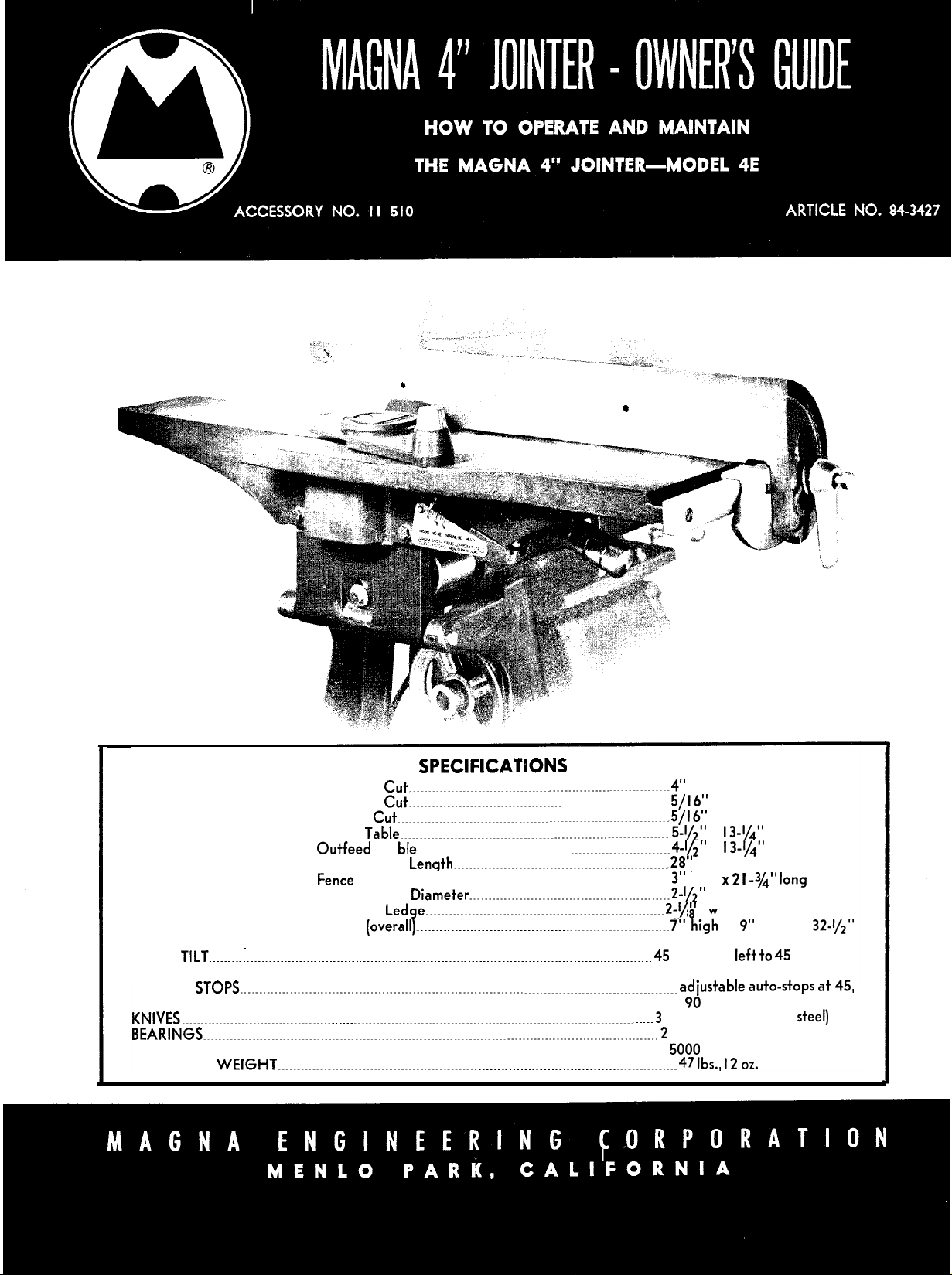
SPECIFICATPONS
CAPACITY____________________________.
Width of
Depth of
Ra
DIMENSIONS______________________._
FENCE
FENCE
TlLT_________I____________________________________________________________________________________________________________
STOPS__________________________________________________________________________________________________________________
lnfeed
Outfeed
Overall Table
Fence_..___....___..___________________________________________________________________3”
Cutter Head
Rabbeting
Jointer
KNIVES._________________________________________________________________________________________________________________________._____
BEARINGS________________________________________________________________________________________________________________________
SPEED
_________________________________________________________________________________________________________________________________
SHIPPING
WEIGHT________________________________________________________________________________________________________47
Cut____________________________________________________________________4”
Cut..____________________________________________._____________________5/
bbet
Cut________________________________________-______________________________~5/
Table______________________________________________________________________
Ta
ble__________________________________________________________________4-1/2”
Length________________________________________________________.Z8”
Diameter____________________________________________________2-~~”
Ledge______________________________________________________________Z-~
(overall)__________________________________________________________________
16”
16”
5-,/z”
x I3-1/4”
x I
3-1/4”
highx 2 I
”
wide
7”
kgh
long
45 degrees
right
adiustable
90
and 45 degrees
-3/4” long
x 9”
wide x
left +o 45
auto-stops at 45,
3 (precision-ground
32-1/2”
degrees
steel)
2 (lubricated for life)
5000
rpm [recommended)
lbs., 12 oz.
HOW TO OPERATE AND MAINTAIN
Magna 4” Jointer--Model 4E
Purchase of the
toward proficient woodworking. Like SHOPSMITH, the
Jointer is designed to accomplish quickly and accurately
many operations requiring tedious hours of labor if done
by hand. Basically, it is a rotary cutter which will plane
edges smooth and square, ready for gluing or assembling.
It will also do a fine job on light surfacing cuts but should
not be confused with the Thickness Planer as Jointers often
are. The latter is a very heavy industrial machine designed
to dress stock to exact thicknesses.
The basic usefulness of the Jointer is illustrated by a
quick preview of standard operational procedure on a
saw-jointer combination such as you have available with
SH6PSMITH.
MAGNA 4”
When cutting
JOINTER
stbck
is
another step
to width you first
establish a smooth, s uare
jointing cut on one
the rip fence during the rip cut on the saw. Then the
second edge is jointed. The rip cut is made oversize to
compensate for stock removal when making the second
jointer cut. Thus
sions and also
no further attention.
Complete information for mounting the MAGNA 4”
JOINTER on SHOPSMITH is contained in the MOUNTING KIT
in the MOUNTING KIT carton.
should be all set, ready for simultaneous operation with
the SHOPSMITH table saw to make homeworkshop
ity
(accessory no.
still easier, more professional and more productive.
3
e
ou
have sized your stock to exact dimen-
oitained
“work-edge“ by making a
ge of the stock. This edge rides
smooth, square edges requiring
I I
52 I)
instruction sheet packed
At
this stage the Jointer
activ-
OUTFEED
TABLE
ADJUSTMENT KNOB
(DEPTH-OF-CUT)
TWO-SOCKET WRENCH
-
QUADRANT
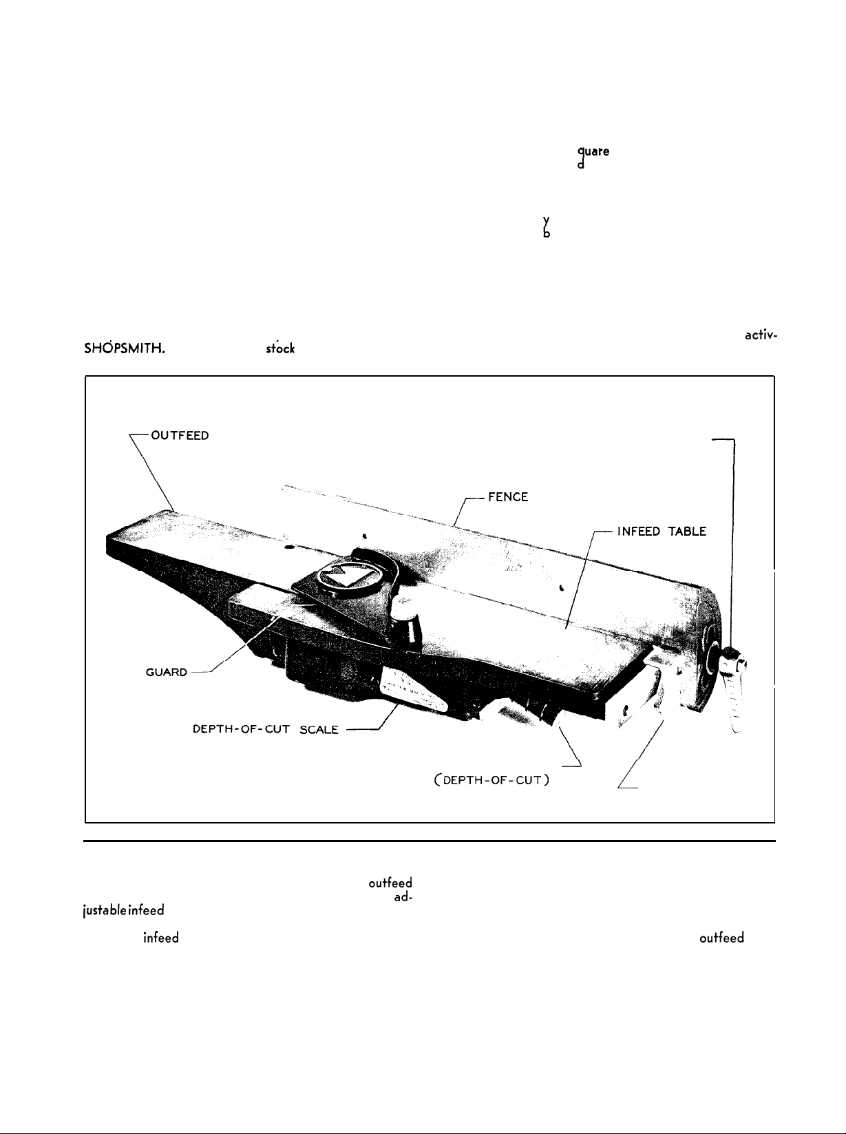
JOINTER
The MAGNA
table (cast integrally with the Jointer base) and an
justable
settings with an easy-to-grip hand knob. How far you
lower the
which is removed during the pass. On the MAGNA
JOINTER this setting does not have to be measured; it
may be taken directly from the indicator scale.
nomenclature
4” JOINTER
infeed
table which is controlled for depth-of-cut
infeed
table determines the amount of wood
(Fig. I), has a fixed
outfeed
ad-
A dual purpose “two-socket” wrench is used to lock the
fence in any position across the tables and at any degree
of tilt.
The guard, which should be positioned as shown for
most operations, may also be located on the outfeed, table
to cover the exposed cutter head behind the fence when
doing rabbeting operations. On very wide rabbets, where
little of the cutter head is exposed, this is not necessary.
2
HOW TO ADJUST THE JOINTER
The Jointer has been factory adjusted and tested for accuracy. It will operate to high standards if used and maintained correctly. Correct procedures for adjustment and periodical checking are described in the following paragraphs. READ THE INSTRUCTIONS CAREFULLY. The MAGNA 4” JOINTER
deserves the best of care.
is a valuable, precision machine which
Knife adjustment
The combination of fixed
adjusted knives in the MAGNA 4” JOINTER make the
one critical Jointer adjustment a very simple matter. The
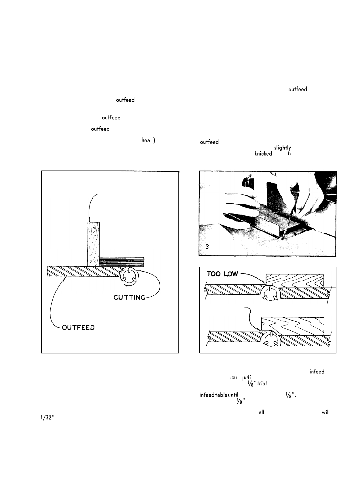
horizontal plane of the
to the cutting circle of the knives. Check this by placing a
straight edge on the
the cutter head. Turn the cutter head by hand
-use hands on the belt, not the cutter
knife is at the top-most point of the cutting circle. The
knife should bare yIscrape the straight edge. If it lifts
the straight edge, the knife is set too high. If it does
not touch at all, the knife is set too low (Fig. 2).
outfeed
/
STRAIGHT
outfeed
outfeed
table so that is juts out over
table and easily
table must be tangent
CAUTION
6
)
until one
hea
EDGE
does not the work will not clear the
a rabbet cut.
Lock
The check on blade height and blade position in the cutter
head should be made on all three knives.
alignment are these (Fig. 4): If, after passing over the
cutter head, the edge of the work hits the edge of the
outfeed
set too low. If the work drops
the pass resulting in a knicked end,
high.
the wedge in place with the three Allen screws.
Operational danger signals which will indicate mis-
table and must be forced across, the knives are
slight1
outfeed
K
t
table during
at the very end of
e
knives are set too
CUTTING1
CIRCLE
OUTFEED
TABLE
2
Make this
is required, loosen the three Allen screws which lock the
knife-retaining wedge. Adjust the two Allen screws on
which the knife rests (Fig. 3). If the knife is too high the
screws should be lowered-if the knife is too low the
screws should be raised.
After the knife is adjusted for height,
tion in the cutter head. The forward edge of the knife
(edge nearest the rabbeting ledge), should extend about
l/32”
check
at both ends of the knife. If adjustment
check
it for posi-
beyond the ron ef t dge of the out-feed table. If it
TOO HIGH
-I
1
4
,
Adjusting for depth-of-cut
Turning the hand knob clockwise lowers the infeed table
for depth- f t d’ to
the pointer, make a l/e”
sure the cut in the wood and, if necessary, adjust the
infeed table until
exactly on the l/e”
which should be made periodically consistent with proper
machine maintenance,
correct.
-cu
a
ius
ments. To check the accuracy of
trial
cut in a piece of stock. Mea-
the cut is exactly I/B”. Set the pointer
mark (Fig. 5). After this adjustment,
aII
other pointer settings
wiII
be

Adjusting the guard
The cap on the guard of the MAGNA 4” JOINTER
contains a spring which supplies the pressure that automatically keeps the guard over the cutter head. During
the pass, the guard covers the unused section of the
cutter head while the work itself covers that area which
is cutting. The side pressure of the guard also helps to
keep the work against the fence. NEVER WORK WITH-
OUT THE GUARD UNLESS
SARY. It was designed for your safety.
IT IS ABSOLUTELY
NECES-
Fence adjustments
In normal operating position the fence should be
perpendicular to the horizontal plane of the tables. To
check, follow this procedure. Use the two-socket wrench
to loosen the nut which secures fence tilt. Set the fence
on the quadrant “zero”
square (Fig. 7). If the fence should require a slight adjustment
loosen the two slotted screws which hold the fence
bar to the Jointer. Adjust the bar until the fence checks
out exactly square to the tables. Lock the slotted screws.
mark and lock it. Check with a
To put the guard in place
(Fig. 6) and slip the hex shaft in t
of the rabbeting ledge while you hold the cap. It is never
necessary to apply excessive spring pressure on the guard
-one full revolution of the cap is sufficient for virtually
all operations.
THEN SET POINTER EXACTLY ON
mere1
‘18
turn the cap clockwise
x
e
hex hole at the front
IN. DEPTH OF CUT
b’;
5
TURN CAP CLOCKWISE
ONE REVOLUTION
The auto-stop for the 90 degree position may be adjusted now (Fig. 8). Bring the stop forward and thread the
screw down until its
screw setting with the nut. Now, when the fence has been
tilted and you want it back to the 90 degree setting,
simply bring the stop forward and tilt the fence up until
the
adiustment
cedure with the fence tilted forward 45 degrees and again
with the fence tilted back 45 degrees. Thus you have
accurate, automatic stops at the three most used fence
positions.
To move the fence across the table loosen the locking
nut (Fig. 9) set the fence where needed and lock the nut.
ADJUST SCREW
LOCK
JAM NUT
end
bears against the stop. Lock the
screw hits the stop. Follow this same pro-
FENCE
\
STOP IN FORWARD
POSITION
8
MOVEMENT ACROSS TABLE LOCKED WITH THIS NUT
9
\
STOP IN NEUTRAL
POSITION
FENCE TILT LOCKED WITH THIS NUT
I-
TWO WAY SOCKET WRENCH

OPERAT ION
The Jointer is used to plane edges square and smooth
and to accomplish other cuts such as those shown in
Fig. IO. Jointing-planing the edge of a board-should
always be done with the grain of the wood. Working
against the grain seldom produces a satisfactory surface
and also increases the danger of kickback (Fig.
Depth-of-cut settings on jointing operations should
never exceed
I/
16”
does a good job and wastes less wood.
Although the jointing operation is a smooth movement
from start to finish it is best shown in three steps. The
best side of the stock is placed against the fence with
the work edge down on the
should be placed as shown to hold the work down on the
table and snug against the fence. THE GUARD SHOULD
BE IN PLACE AT ALL TIMES AS SHOWN. The guard
is removed in some of the photos but this is only to show
the operation more clearly.
t/s”.
Normally, a setting of from
infeed
table (Fig. 12). Hands
I I).
l/32”
to
RIGHT
WRONG
I I
DIRECTION OF FEED
As the work advances over the cutter head the guard
moves aside to permit its passage. The left hand does
most of the work of keeping the stock snug against the
fence and down on the tables (Fig.
hand moves it forward. Some operators object to passing
either hand over the cutter head but if the work is wide
enough and the guard is used, there is little danger if
the hands are positioned as shown. It also eliminates the
need for repositioning the hands during the pass-a procedure which could be more dangerous.
At the
end
of the cut (Fig.
about the same position. Avoid heavy downward pressure
at the end of the cut since this might tilt the work into
the cutter which would result in a gouged end.
l3),
while the right
14)
the hands are still in
5

The two holes in the Jointer fence permit mounting a
J/4”
plywood auxiliary fence when a quantity of extra wide
boards must be jointed. Attach it with two I” F. H. screws
inserted from the back side of the Jointer fence (Fig. 15).
Jointing end grain requires two passes (Fig.
the first pass to the point where the work has passed about
I” across the cutter head. Then turn the work around and
complete the pass as shown.
The Jointer may also be used to do light surfacing
operations. Depth-of-cut should never exceed
work is placed flat on the
the cutter head as in jointing (Fig.
the combination pusher-hold down. This tool, which you
can easily make yourself (Fig.
surfacing operations.
infeed
table and advanced over
IT).
Notice the use of
l8),
should be used on all
16).
I /
16”.
Make
The
Rabbeting
Rabbeting is done by bringing the fence across the
table and locking it a distance away from the ends of the
knives equal to the width of the rabbet required.
of-cut for the rabbet is gauged by lowering the
table. The
cutter
to
5/l
wide (over
tion so that t e same maximum depth-of-cut adjustment
should be observed. However, the full depth-of-cut can be
achieved by making successive passes lowering the table
after each pass until the cut is complete.
For rabbets that are
cut can be attained in two passes. Full depth-of-cut on
rabbets under t/z”
Support for the work is provided by the
and rabbeting ledge regardless of whether the work is
held flat on the table (Fig.
ass is made by advancing the work over the
hea
cf
as in jointing. Rabbet cuts may be made up
6”
deep and 4” wide. When the rabbet is extra
the action is similar to a surfacing opera-
I” ,
I,
to
I”
l/z”
can be accomplished in a single pass.
wide the full
19),
or on edge (Fig. 20).
depth-of-
infeed
Depth-
infeed
table
lb
FIRST PASS
SECOND PASS
Bevel cuts
To make bevel cuts, tilt the fence to the angle desired
(Fig. 2
1)’
and pass the work across the cutter head while
maintaining full contact with the fence. It is
sary to make more than one pass before the Level is
complete.
6
usual1
neces-

Recessing
A
recess cut (often called stop
most often
in base members and t
stand legs. It is formed by using sto
ends
of the cut. The work
a
block and d
vanced
Then it is turned
shown in Fig.
23.
until it hits the rear block (Fig. 22).
and a second pass made.
is
R
place
ed
chamfering) is used
e
bottoms of
table and
blocks to gauge the
B
against the forward
The result is
NOTE: CENTER MAY BE CUT OR SANDED OFF
-
OR RETAINED AS DECORATIVE DETAIL.
CARE OF JOINTER KNIVES
With proper care and occasional honing the Jointer knives will function for a long time without regrinding. Occasionally the
knives should be cleansed of the gum and pitch which will adhere to them. If this accumulates it will reduce the efficiency of the knives.
A good way to clean them is to spray them with SHOPSMITH RUST PREVENTIVE (accessory no.
minutes and then wipe off with a rag.
To hone them, wrap an
covered end of the stone on the table so that the exposed end juts out over the cutter head (Fig. 24). The cutter head should be
turned to allow the stone to rest flat on the bevel of the knife. Hold the cutter head in this position (by gripping the drive belt) and
move the stone back and forth across the knife. Hone an equal amount on each knife.
When knives are chipped or otherwise dulled beyond resharpening by honing they must be removed from the cutter head and
refinished on a grinding wheel. Through the use of special homemade jigs this can be accomplished on the table saw (Fig.
losing
SHOPSMITH as a tool sharpener (Fig. 26). (Note-Figs.
FOR EVERYONE.)
Knives that have been reground enough to bring the knife width down to less than I
recommended.
oilstone
in paper leaving about I”
of it exposed. Lower the
25 and 26 are from the new book POWER TOOL WOODWORKING
l/16”
I2
049).
Let this soak in for a few
infeed
table about l/g” and rest the
should be discarded. Further use is not
25)’
paper-
or by
GENERAL MAINTENANCE AND LUBRICATION
The two grease-sealed bearings on which the cutter head revolves do not require lubrication.
attention for the life of the Jointer.
The ground surfaces of the fence,
occasional coating of hard paste wax will do a good job.
If the Jointer is idle for long periods of time the surfaces should be coated with SHOPSMITH RUST PREVENTIVE SPRAY.
Occasionally, place a few drops of light machine oil on the fence bar, in the semi-circular groove in the quadrant, and on the
infeed
table inclined ways.
The MAGNA JOINTER
many people who still do not own a SHOPSMITH
is given in Fig. 27.
as exceptionally long tables for a 4” Jointer. For this and other reasons which mark it a superior machine,
h
infeed
table and
outfeed
table should be protected to insure clean, smooth operation. An
h
ave requested information for mounting it as a single-purpose tool. This information
They will function without further
4”
JOINTER STAND
ASSEMBLE WITH GLUE AND FINISHING NAILS.
MOUNT JOINTER WITH 3,
3,
‘/4” SQ.
NUTS, AND
INSTALL STOPS WITH N0.8~1” FLAT HD
USE 45 INCH. BELT.
LEG SECTION
I
..I
SIDE
PANEL
FRONT
LEG,
\ 3/8”X450 )
+---
/
‘14 it
0.
V4
”
WASHERS.
I5 ”
- 14”
2 ” STD.
----A
-----I
SQ.
-- SLIDE STOPS
HD. BOLTS,
WOOD SCREWS.
DRILL 3,
5/16”
SEE DETAIL B FOR
LOCATION OF HOLES
TOP,
3/4”
PLYWOOD
SLIDE,
3/8”
SIDES,
l/2” ”
BACK,
l/2* ”
SHEU; 7/8”
LEGS, I
l/2 0
SLIDE STOPS . . . . . .
l/2 ‘I.
. STOCK
SHELF STOPS. . . . . .
V8”O xl2
”
”
HOLES.
I’2
,-‘--
*Tiiu
SECTION A - A
/------
7
I7
v$--pd
DETAIL
B
27
/STONE
24
WITH END WRAPPED IN
INFEED TABLE
’

P 6306
B 2906
P I
I26
B 2904 _
p
--_-
-------
___.__
MAGNA 4” JOINTER PARTS LIST
_,
/-----6307
Asm bly.
NQ.
B 2959
P 1653
A 2951
A 2950
A 2960
P
1385
B 2793
P 6308 Screw--Machine
P 1404
A
2912
P
1507
P
A
2961 Washer-Spring
P
I15140
B
2906
B 2902
P 6306
A 3050
P 6307
P 1529 Washer-Lock
B 3051
P 1014
II5130
D
2921
P 6300 Screw---Set
P
1449 Nut-Jam
P 6304 Screw-Hex. Cap
B 2924 Wrench--Fence Lock
P 1450 Nut-Hex.
P
1528 Washer
B 3076
I15131
II5150
KIescription
Indicator---Depth
Screw-Drive
Screw--Depth
S+Iid-Table Mourit
Pointer-Depth
Screw--Pan Head
Bar-Fence
Not-Square
Knob-Adjusting
Washer
1451
Nut-Hex.
1917
Key-Allen
CUTTER HEAD ASSEMBLY
Blade
Wedge
Screw-Sot. Set
Screw-Set
Screw-Hex. Cap
Puliey
Screw---Sot. Set
FENCE ASSEMBLY
Fence
Pin-dowei
Qtladrant
GUARD ASSEMBLY
. . . . . .
. . . . . . , .
. . . . . . . . . . 3
. . , . . . . . . 3
. . . . . . . . .
. . . . . . . . . . I
. . . . . . . . .
Assembly
. . . . . . . . I
. . . ~ . . . .
. . . . . . ~ . I
. . . . . . . .
. . . . . . .
. . . . . . . .
. . . . . . . .
. . . . . . I
. . . . . . .
. . . . . . f I
. . I .
. . . . . , .
. . . . . I
. . . . , .
. I . . . .
. . . . . .
. . . . . .
. . . . . .
. . . . . ~ .
. . . . . .
. . . . .
. . . . . . . .
. . . . .
. . . .
. . . . .
.
.
. . I
.-
3
3
9
6
2
I
3
2
I
2
I
I
I
I
I
I
I
I
I
I
2
2
15.95 7
4.95 8
I
.20 5
.I0
_
.25
_. IO
.I5
I
.05
3
.lO.
3
I .OO _
.I0
__ 3
.05
3
.05 3
.05
.lO.
3
.I0 ._..
.lO.
3
.I0
3
7.95 IO
.lO.
3
.05
3
.05
.05
.
3
3
IO
When ordering parts from the above list be sure to supply part
number and description for each item plus the model and serial
3
3
3
number of your machine. This information should be provided to the
dealer from whom you purchased the Jointer.
Because the
aligned it is not advisable to supply them separately. Should it ever
become necessary to replace either of the tables, ship the entire
chine, less mounting kit, guard and fence to the factory nearest you.
MAGNA ENGINEERING CORP.
Berkeley, California
tory job.
order a new cutter head assembly
one to us for rebuilding.
When it is necessary to return parts directly to the factory be
sure to package securely, insure sufficiently and ship prepaid.
Parts which are
called out
require factory trained help for replacement-therefore they cannot
be supplied as replacement parts.
infeed
table and
2550 Ninth Street
If the bearings or the
shown in the exploded views but which are not
in the parts list are either permanently assembled or
outfeed
table must be perfectly
MAGNA CORPORATION
12819 Coit Road
Cleveland, 0 hio
cutter head ever need replacing,
( # I
I5I40),
or return the old
ma-
Should you desire further information on Jointer techniques and procedures as well as detailed instructions
for all power tool applications, see the new
R. J.
DeCristoforo,
which is available through your local SHOPSMITH dealer.
book,
Magna Engineering Corporation
8 53
9048
Copyright
1953---Magna
Engineering Corporation
POWER TOOL WOODWORKING FOR EVERYONE by
PLANTS IN BERKELEY AND CLEVELAND
 Loading...