

Shopify MotoMask PRO User Manual
USER'S MANUAL

CONTENTS
Brief description
2
Attention
2
Parts overview
3
Masking roller assembly
7
Frame assembly procedure
10
Attaching the frame to the wall
22
Testing the product
24
How to retrofit the masking roller
25
Size and measurement overview
28
Masking system setup
30

BRIEF DESCRIPTION
2
Thank you for purchasing the multi masking MotoMask PRO screen.
The masking system is retrofittable and can be purchased and installed later on.
FEATURES
• Separate frame and masking system.
• Built-in wireless RF receiver, as well as RS485 for smart home setups.
• Automatically stops if an obstacle is met to protect the motor.
• The position of the masking can be fine tuned and stored using the remote.
• For the 16:9 version, you can even close the entire masking fabric
while not in use.
• Professional grade quality for maximum rigidity even for very large screen
XXL sizes.
ATTENTION
Please read following instruction before installation of the product:
• Please handle with care.
• During installation, please choose a suciently sized, clean area.
• Lifting and attaching this very heavy screen system to the wall after
assembly normally requires 3 or more people.

PARTS OVERVIEW
3
Outer
frame
Frames>3m in width are divided.
The quantity of sections depends
on the size of the frame.
Inner
frame
Frames>3m in width are divided.
The quantity of sections depends
on the size of the frame.
DrawingItem Description
"L" shape
connection part 1
Used for connecting the inner and outer frame.
Quantity depends on the size of the frame.
L" shape
connection part 2
Used for connecting the corners
of both inner and outer frame.
Quantity: 16 PCS
“U” shape
connection
part 1
Used for connection of the inner and outer
frame. Quantity depends on the size
of the frame.
“U” shape
connection
part 2
Used for fixing the supporting bar.
Quantity depends on the size of the frame.
Supporting
bar
Diameter: 30 × 30mm
Quantity and length depends on the size
of the frame.
Lower wall
mounting bracket
Used for mounting the lower section
of the frame. Quantity depends on the size
of the frame.
Upper wall
mounting bracket
Used for mounting the upper section
of the frame. Quantity depends on the size
of the frame.

4
Preinstalled
metal 1
Used for fixing the supporting bar
connector. (Preinstalled in support
bar). Quantity depends on the size
of the frame.
Preinstalled
metal 2
Preinstalled in inner and outer frame.
Quantity depends on the size
of the frame.
Corner connector 2
for upper outer
frame.
Used for connecting the upper corners
of the outer frame. Please notice the
dierence from the other included
corner connectors.
Quantity: 2PCS
Preinstalled
metal 3
Used for fixing the supporting bar.
Quantity depends on the size
of the frame.
Connector
parts
Used for connecting the inner
and outer frame >3m wide. Quantity
depends on the size of the frame.
Corner connector 1
for upper outer
frame.
Used for connecting the upper corners
of the outer frame. Please notice the
dierence from the other included
corner brackets. Quantity: 2PCS
Grip rail
Used to attach the UltraWeave
screen fabric. Quantity depends
on the size of the frame.
DrawingItem Description
3mm inner
hexagon
spanner
4mm inner
hexagon
spanner
Quantity: 4PCS
Corner connector 3
for the lower corners
of the outer frame.
Used for connecting the lower two
corners of the outer frame. Please notice
the dierence from the other included
corner connectors. Quantity: 4PCS
Quantity: 4PCS
5
M6*8 screws
Quantity depends on the size
of the frame.
M6*8 set screws
Used for fixing metal in the frame
(most are pre-installed). Quantity
depends on the size of the frame.
DrawingItem Description
Gloves
Quantity: 2
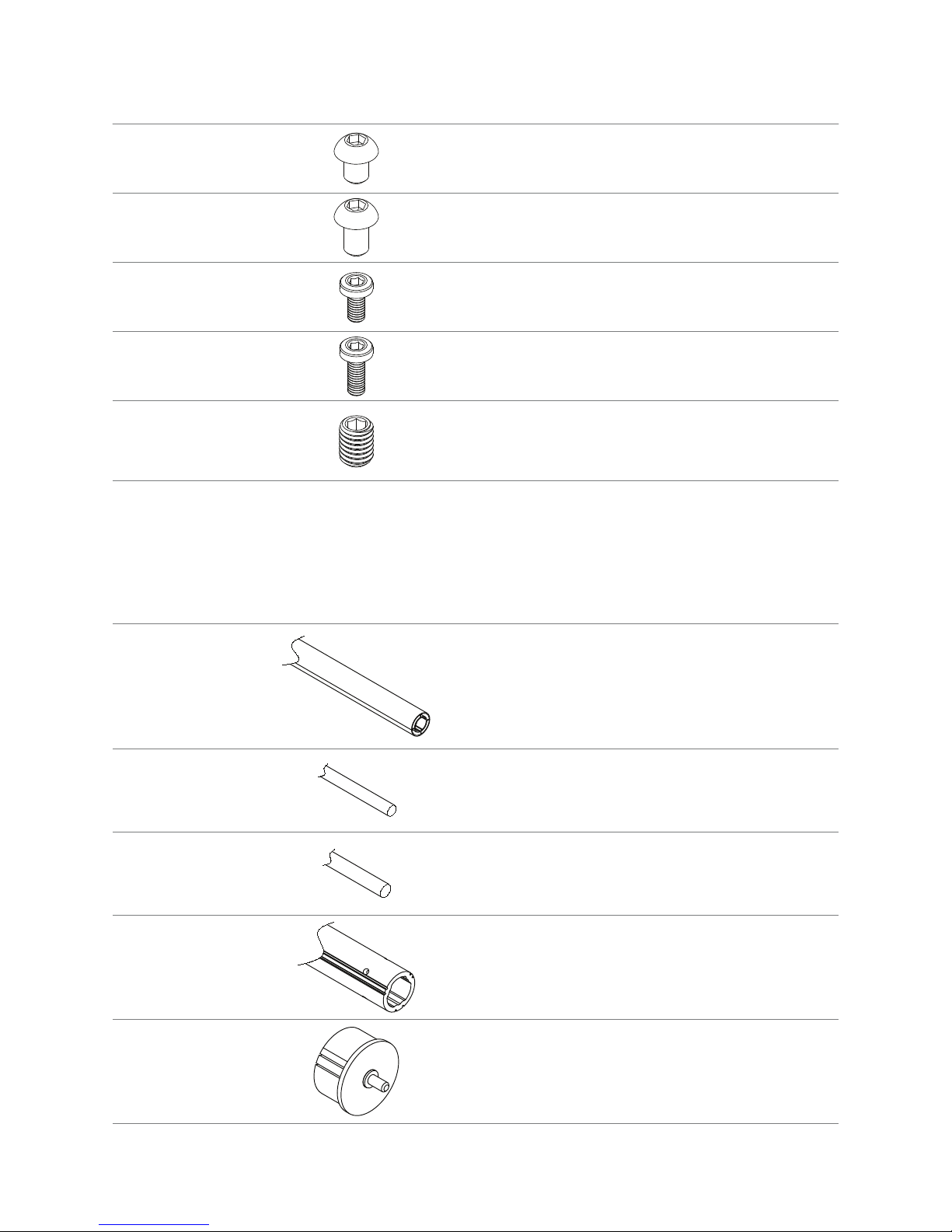
Tail
plug
Please make sure the tail plug is installed
on the correct side before securing it into
the masking roller.
Quantity depends on the size of the roller.
Weight
steel rod
Roller
connection
parts
70mm
diameter
roller
Masking rollers>3m
are divided in two or more parts.
Quantity depends on the size of the roller.
MASKING ROLLER PARTS OVERVIEW
Glass fiber
bar
Quantity depends on the size of the roller.
Length: 300mm.
Pre-installed in divided rollers.
Quantity depends on the size of the roller.
M6*10 screws
Quantity depends on the size
of the frame.
M6*12 screws
Quantity depends on the size
of the frame.
M6*20 screws
Quantity depends on the size
of the frame.

6
DrawingItem Description
Cross screwdriver
Used for the 70mm diameter roller.
(Only supplied for divided masking rollers.)
Right masking
roller bracket
Installed on the (right) motor side.
Quantity:1PCS
Left masking
roller bracket
Installed on the tail (left) side.
Quantity:1PCS
Bottom
bar
Bottom bars >3m
are divided in two or more parts.
Quantity depends on the size of the roller.
Bottom bar
connection
parts
Length: 120mm
Used to connect the bottom bars if divided.
Quantity depends on the size
of the masking roller.
Tubular motor
Motor and integrated control system
110V (US) or 220V.
Power cable
EU or US type.
Fabric for the
masking roller
Only supplied separately for the divided
masking rollers, pre-installed for the
non-divided version (<3m).
Quantity:1PCS
M4*6 screws
Used for the bottom bar.
(Only supplied for divided masking rollers.)
MASKING ROLLER ASSEMBLY
(only applicable for divided rollers, <3m rollers are pre-assembled)
7
Required tools for the installation.
• Fabric for the masking roller (supplied)
• 3M double sided tape (supplied)
• Cross screwdriver (supplied)
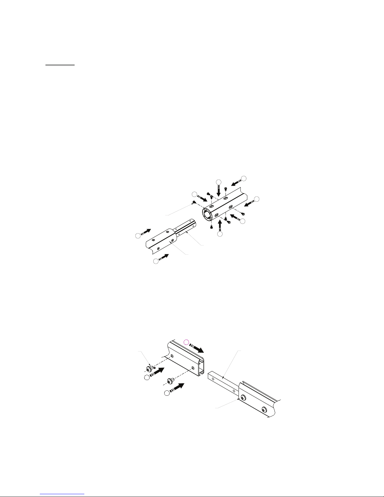
Step 1: Connect the divided roller.
• Most of the parts required for connecting the masking roller is already pre-installed.
• Align the two parts, slide the parts together and then secure them with the included screws.
Sliding the two parts together can sometimes be a bit tricky as the spacing is very tight
(it has to be to ensure sucient rigidity). If needed, please use a rubber hammer
or a similar device to help sliding the parts together.
Drawing 4-1
Step 2: Connect the divided bottom bar.
• The connection parts are already fixed.
• Insert the connecting piece into the other lower bar part and then tighten the screw to complete
the connection of the divided bar. (Note: the screw used for securing the bottom bar must be
facing the back (i.e. not the audience) of the screen.)
This side
has been fixed
1
Connection
parts
2
2
Drawing 4-2
M4*6 screws
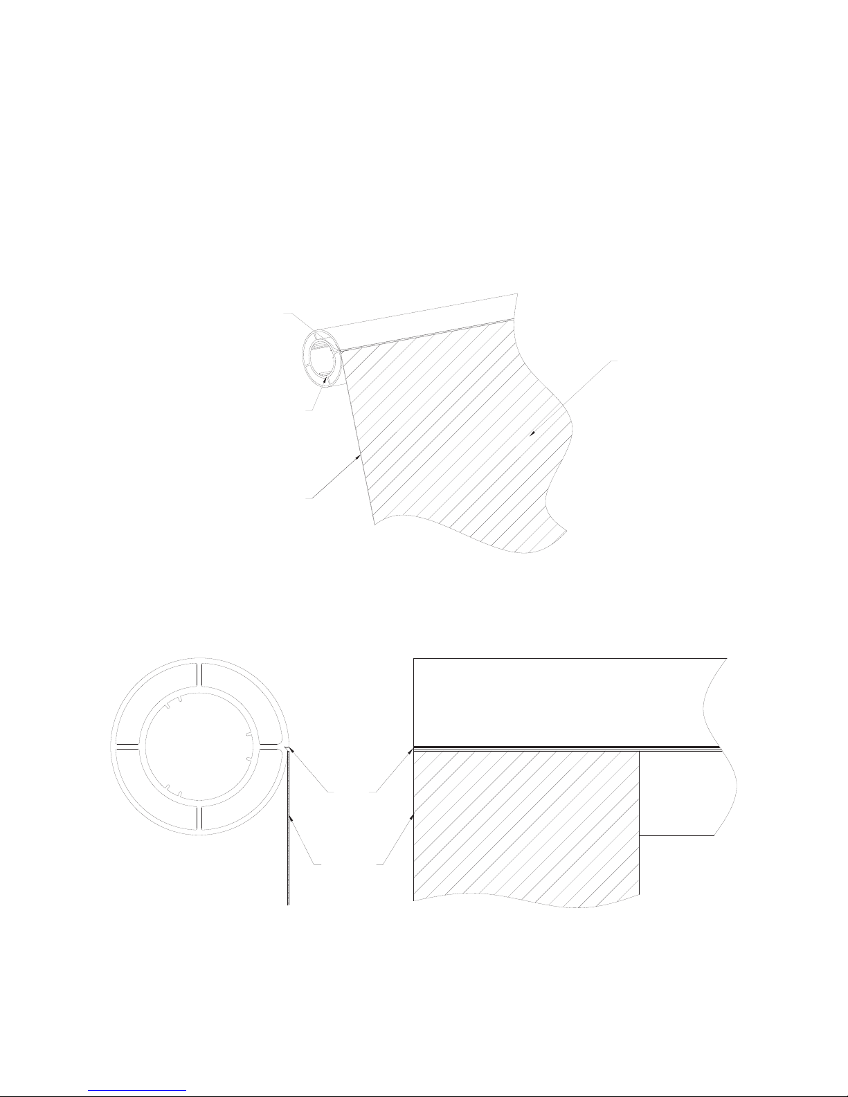
Step 3: Fixing the masking fabric to the roller.
1. Please make sure you find a clean and suciently sized area to perform the installation.
Connection parts
M6*10 Screws
These parts are pre-fixed
1
1
1
1
2
2
2
2
8
2. Please attach the included 3M double sided tape to the masking roller, just below the small step
found in the roller.
3. Place the roller tube with the motor side to the left and tail side to the right. Please note that
when installing the masking roller into the frame later on, this direction is opposite (seen from
the back of the frame), i.e. the motor is on the right side and tail on the left.
4. Install the fabric flush with the edge at the left side and install it towards the right as per
drawing 4-3. There will be an approximate gap of 5mm left on the right (tail) side.
For the 2.40:1 2-way masking systems, please attach the left side flush, but use a 5mm gap
on the right (tail) side as well, as per drawing 4-5.
Masking fabric
Edge of the masking fabric
Edge of the roller
Drawing 4-3
Step
Drawing 4-4
Step
Masking
fabric

9
5. Please insert the glass fiber bars into the lower pocket of the masking fabric as per drawing 4-6.
6. Please insert the weight steel rod in the cavity just below as per drawing 4-6. Please note that
the connection piece might block the passage, so you might need to lift and navigate a little
at this section.
Drawing 4-6
Drawing 4-5
Step
Masking
fabric
5mm
Back side
step
Weight
steel rod
Glass fiber bar
Bottom bar
Bottom bar connection parts
Viewing side

10
How to distinguish the placement of corner connection parts and position
of the masking roller.
Drawing 4-5 (Viewed from the back of the frame.)
Motor sideTail plug side
Corner connector 1
Corner
connector 2
Corner connector 1
Corner
connector 2
M6
M6
M6
M6
FRAME ASSEMBLY PROCEDURE
Step 1: Put the inner and outer frame parts according to the layout in drawing 5-1-1.
All parts have corresponding numbers attached to them.
• The frame section parts are labeled as per drawing 5-1-1.
• For smaller frames, the numbers are corresponding to the number of parts that make out the
frame, always starting with part 1 from the right short side. For example, for a <3m non-divided
frames, the total number of components of both the outer and inner frame is 4 (per frame
section), the right short side has #1, the lower long side has #2, the left short side #3 and finally
the upper long side #4.
 Loading...