

Shopguard Systems S682TX Users Manual
Service Manual
JuniorGuard series
Rev. March/03

Table of contents:
1. Overview of the 8.2 MHz systems
2. Factors to be considered during installation
3. Parameters of Juniorguard
4. The transmitter board (TX) and its settings
5. Overview of the receiver board (RX) and the test box, possible settings
6. Examples of complete systems
7. Addendum
8. Recommended tools
9. FCC

1.Overview of 8.2 MHz systems
The transmitter of the radio frequency system emits frequency modulated (generally
with ±10% frequency deviation) radio signal with 8.2 MHz carrier. The security labels
(tags) include LC resonator circuits tuned to a particular frequency (8.2 MHz ±5%). In
the field radiated by the antenna they generate a signal clearly detectable by the
receiver. The receiver analyses this signal in several cycles and based on a well-defined
algorithm, according to different criteria – supposed that the signal shows the attributes
of a real label – and gives an alarm. This alarm is generally an audible and visible
signal, but the relay outputs are capable of driving other external devices, too. In the
system developed by Shopguard we use microprocessor control, digital signal
processing and correlation filters, therefore, signal detection is extremely reliable and
the number of false alarms is minimal. The system handles the complete range of
available tags: hard tags (drop-shaped and circular) with prints defined by the customer,
guard frames for goods (safers) with wire loops (swinging coil with a single winding) or
paper labels that fit for CDs, double CDs, DVDs, MCs, VIDEOs and GAMEBOY
modules, as well as paper labels that can or can not be deactivated. The deactivator
device for paper labels can be integrated into the system; removers for hard tags and
opener for savers are also available.

2. In this section we list the circumstances that can disturb the system’s
proper operation.
¾ The distance from electronic cash registers, and computer displays (and from
other digitally operated equipment) should be at least 70-75 cm,
¾ Cables carrying pulse signals (e.g. cables connecting the keyboard to the alarm
centre, cables connecting to regulators of air condition systems) should run at
least ~70 cm from the antenna,
¾ Cables of power line equipment (230 V / 400 V) may not run in parallel
(vertically) with the antenna body within ~1.5 m,
¾ Power cables should not run in the basement between the antennas,
¾ The distance between metallic objects, mirrors and the antenna should be at least
30-40 cm,
¾ Moving grids, shades, automatic doors may not be placed within ~0.5 m (1m is
recommended),
¾ At switch-on (and permanently in case of faulty ignition circuit), high voltage
advertising lights and any kind of gas-discharge tubes (e.g. halides lamps)
produce a noise with many harmonics that reduces the system’s operability,
¾ In order to avoid mutual disturbances, the nearby goods EAS (Electronic Article
Surveillance) systems must be synchronized,
¾ No labels should be placed near-by the power cable,
¾ No labels should be placed beside the antennas, within a range of 1.5 – 2 x the
response distance,
¾ If possible, the antennas should not be placed beside metallic or metal bearing
columns,
¾ The RX (receiver) antenna must be placed far away from the noise sources.
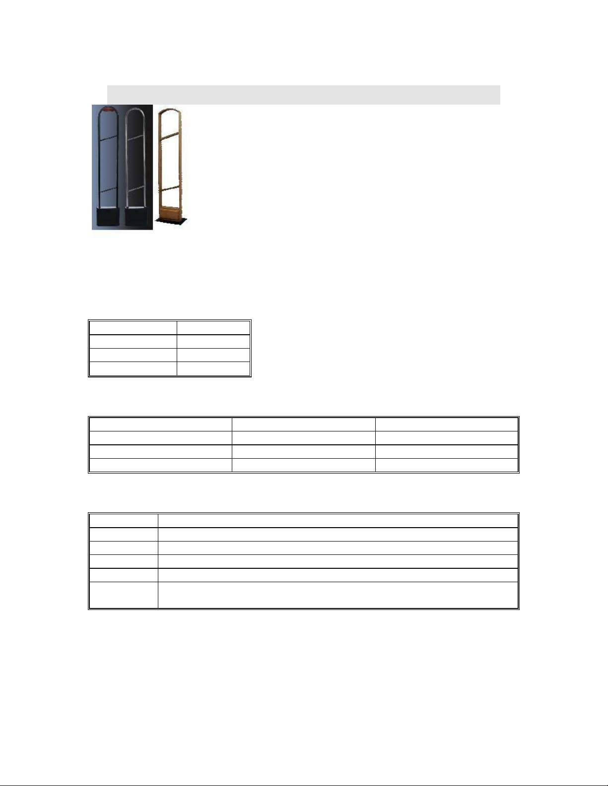
3.Parameters of Juniorguard
It’s a very attractive styling antenna. It’s available in black, chrome, antique silver and wood
variant.
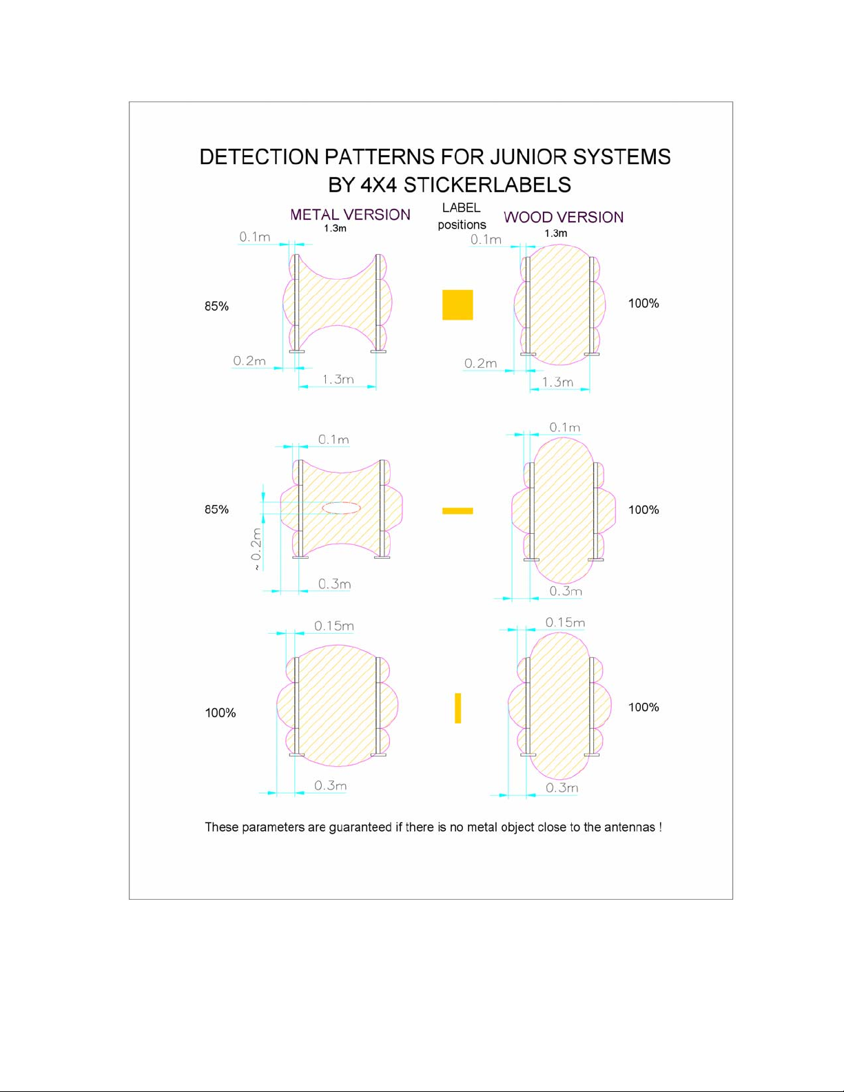
Available detection distances:
TAGS: DISTANCES:
40x40 mm paper 130 cm
Mini hard tag 160 cm
Round hard tag 160 cm
The necessary settings:
TX RX
Impedance JP 10, 11 at 3 Tuning capacitor JP 12, 13 at 1 JP 9 at 1
Damping resistor It’s in inside of antenna It’s in inside of antenna
The main characteristic parameters of the system:
Height: 1.68 m / 5.51 feet
Width: 0.33 m / 1.08 feet
Depth: 0,09 m / 0.29 feet
Weight: 8 kg
Material: Chromium or colour steel tube
Power: 220-240 VAC @ 50 Hz (EU)
110-120 VAC @ 60 Hz (US)
4. The transmitter board (TX) and its settings
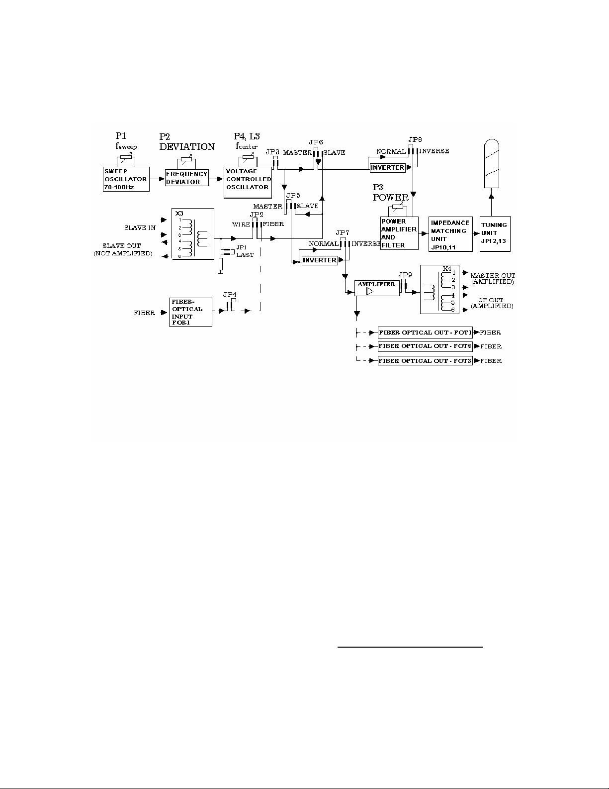
4.1. Schematic diagram of the transmitter board:
The above figure shows the schematic diagram of the transmitter circuit. Functions of the
individual blocks are:
Sweep oscillator:
Provides the approx. 82 Hz modulation frequency for VCO.
Voltage controlled oscillator (VCO):
This is a voltage-controlled oscillator with 8.2 MHz output frequency. This output frequency
is frequency modulated by the sweep generator. The frequency deviation is generally ±10 %.
Slave inputs:
If the antenna operates as a slave, we drive the power amplifier with the signal of a master
transmitter. The connection can be established with cables. We use this solution with few
antennas only, because it may collect and forward noises and it may cause unwanted
couplings that may make impossible to operate larger systems. In larger systems (in case of
certain bad environmental conditions even with 2 antennas) we use optical connections,
because they are insusceptible for external electric disturbances, do not cause couplings but
they are expensive, need special tools and knowledge. Optical interfaces are optional!
The
optical input is FOR1.
Phase inverter circuits:
In case of several transmitter antennas, inversion of the antenna signal phase may be needed,
because the antenna signals block out each other in counter phase.
Slave outputs:
 Loading...