

Page 1
READ THIS FIRST
STEP A
Model W1875
***IMPORTANT UPDATE***
Applies to Models Mfd. Since 01/21
and Owner's Manual Printed 11/20
Phone #: (360) 734-3482 • Tech Support: [email protected] • Web: www.woodstockint.com
The following changes were recently made since the owner's manual was printed:
• Miter Slot to Blade Parallelism on Page 50 of the owner's manual has been revised.
Aside from the information contained in this update, all other content in the owner's manual is
applicable and MUST be read and understood for your own safety.
IMPORTANT: Keep this update with the owner's manual for future reference. If you have any further
questions, contact our Technical Support.
Revised Miter Slot to Blade Parallelism
Your table saw will give the best results if the miter slot
is adjusted parallel to the blade. If the miter slot is not
exactly parallel, your cuts and your finished work will be
lower in quality, but more importantly, the risk of kickback
will be increased.
Tools Needed Qty
Combination Square ............................................1
Marker
Flat Head Screwdriver
To adjust blade parallel to miter slot, do these steps:
1.
2.
3.
4.
............................................................1
DISCONNECT MACHINE FROM POWER!
Tilt blade to 0°, raise blade all the way, then
remove blade guard and anti-kickback pawls.
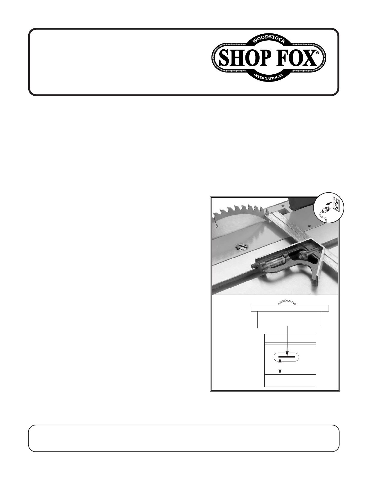
Use combination square to measure distance from
miter slot to a carbide tip on blade, as shown in
Figure 64. Make sure face of square is even along
miter slot.
With end of square just touching blade tip, lock
square in place. Now, mark carbide tip with a marker where you made this measurement.
1
⁄4" ....................................1
Blade tilted to 0º
Front
A
Figure 64. Making first slot-to-blade
measurement at 0°.
COPYRIGHT © OCTOBER, 2022 BY WOODSTOCK INTERNATIONAL, INC.
WARNING: NO PORTION OF THIS MANUAL MAY BE REPRODUCED IN ANY SHAPE OR FORM WITHOUT
THE WRITTEN APPROVAL OF WOODSTOCK INTERNATIONAL, INC.
Printed in China#22495CS
Page 2
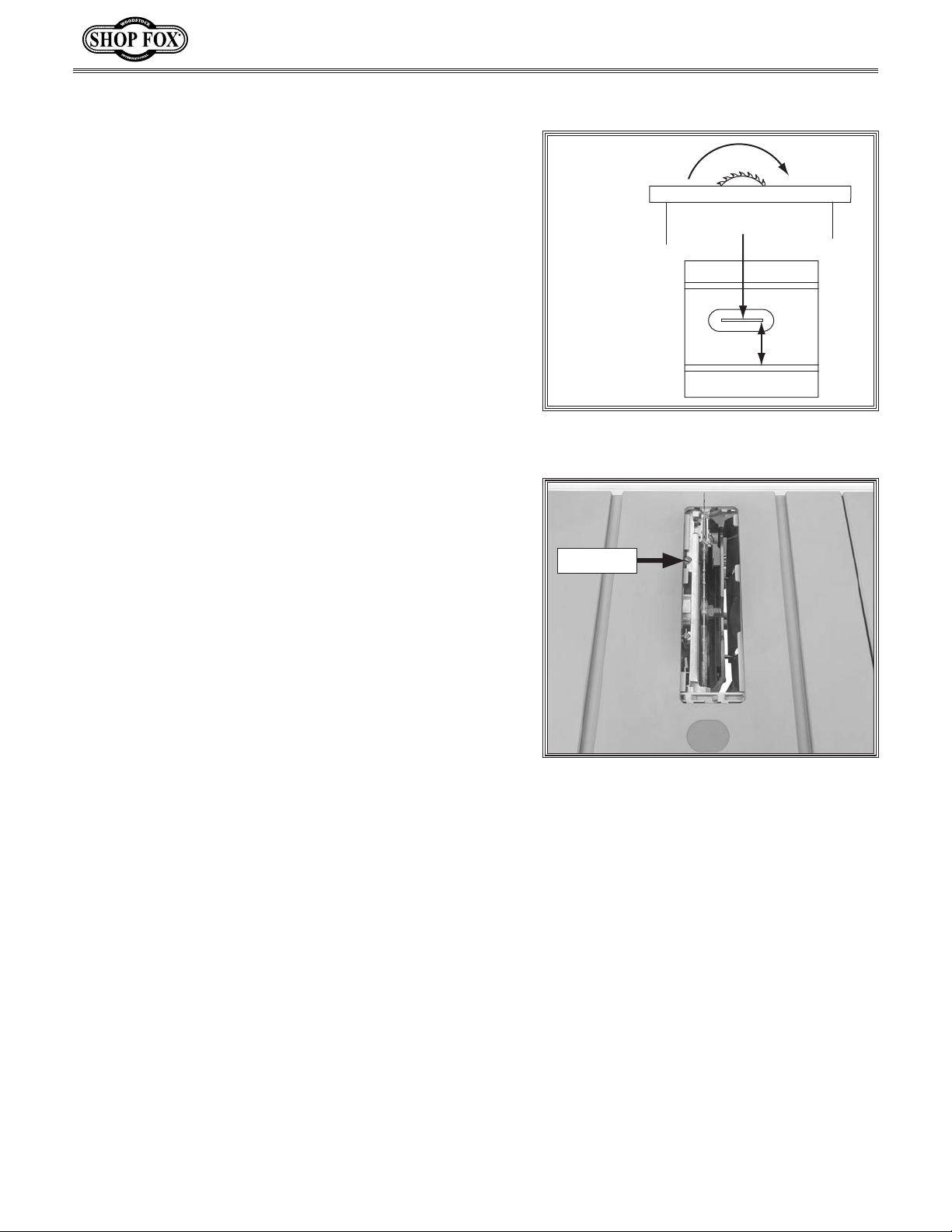
Rotate marked blade tip to other end of table insert.
5.
6.
Slide square down to other end of table insert and
compare distance from marked blade tip to end of
square, as shown in Figure 65
.
Model W1875 (Mfd. Since 01/21)
STEP B
— If blade tip measurement is equal on both sides,
blade is parallel to miter slot.
If blade tip does not touch end of square similar to
—
first measurement, blade parallelism eccentric will
need to be adjusted. Proceed to Step 7.
Remove table insert.
7.
8. Adjust eccentric shown in Figure 66 to adjust blade
angle in relation to miter slot.
Turn eccentric clockwise to adjust rear of blade
—
and spreader/riving knife toward motor.
Turn eccentric counterclockwise to adjust rear of
—
blade and spreader/riving knife away from motor.
Repeat Steps 3-8 until blade and miter slot are par-
9.
allel.
Blade tilted to 0º
Front
B
Figure 65. Making second slot-to-blade
measurement at 0°.
Eccentric
Install table insert, blade guard, and pawls.
10.
Figure 66. Location of blade parallelism
eccentric.
-2-
Page 3
MODEL W1875
BENCHTOP TABLE SAW
OWNER'S MANUAL
(FOR MODELS MANUFACTURED SINCE 1/21)
Phone: (360) 734-3482 • Online Technical Support: [email protected]
COPYRIGHT © NOVEMBER, 2020 BY WOODSTOCK INTERNATIONAL, INC.
WARNING: NO PORTION OF THIS MANUAL MAY BE REPRODUCED IN ANY SHAPE OR FORM WITHOUT
THE WRITTEN APPROVAL OF WOODSTOCK INTERNATIONAL, INC.
#20601AI Printed in China
Page 4
This manual provides critical safety instructions on the proper setup,
operation, maintenance, and service of this machine/tool. Save this
document, refer to it often, and use it to instruct other operators.
Failure to read, understand and follow the instructions in this manual
may result in fire or serious personal injury—including amputation,
electrocution, or death.
The owner of this machine/tool is solely responsible for its safe use.
This responsibility includes but is not limited to proper installation in
a safe environment, personnel training and usage authorization,
proper inspection and maintenance, manual availability and comprehension, application of safety devices, cutting/sanding/grinding tool
integrity, and the usage of personal protective equipment.
The manufacturer will not be held liable for injury or property
damage from negligence, improper training, machine modifications or
misuse.
Some dust created by power sanding, sawing, grinding, drilling, and
other construction activities contains chemicals known to the State of
California to cause cancer, birth defects or other reproductive harm.
Some examples of these chemicals are:
• Lead from lead-based paints.
• Crystalline silica from bricks, cement and other masonry products.
• Arsenic and chromium from chemically-treated lumber.
Your risk from these exposures varies, depending on how often you
do this type of work. To reduce your exposure to these chemicals:
Work in a well ventilated area, and work with approved safety equipment, such as those dust masks that are specially designed to filter
out microscopic particles.
Page 5
Contents
INTRODUCTION .....................................2
Woodstock Technical Support
Machine Specifications
Identification
Controls & Components
Glossary of Terms
SAFETY ...............................................9
Standard Machinery Safety Instructions
Additional Safety for Table Saws
Preventing Kickback
Protecting Yourself From Kickback
ELECTRICAL ....................................... 13
Circuit Requirements
Polarized Plug
Extension Cords
SETUP .............................................. 15
Unpacking
Items Needed for Setup
Hardware Recognition Chart
Inventory
Machine Placement
Assembly
Dust Collection
Test Run
..................................... 6
................................... 14
................................ 14
....................................... 15
........................................ 17
......................................... 18
................................. 20
.......................................... 21
.......................... 3
................................ 8
........................... 12
.......................... 13
............................ 18
.................. 2
......................... 7
...... 9
............ 11
.......... 12
....................... 15
................. 16
SHOP-MADE SAFETY ACCESSORIES ............ 41
Featherboards
Push Sticks
Push Blocks
ACCESSORIES ...................................... 46
Table Saw Accessories
MAINTENANCE .................................... 47
General
Cleaning & Protecting
Lubrication
SERVICE ............................................ 49
General
Blade Angle Indicator
Miter Slot to Blade Parallelism
Spreader or Riving Knife Alignment
Fence Scale Calibration
Table/Dado Insert Adjustment
Calibrating Fence to Blade
Miter Gauge Adjustments
Brush Replacement
Troubleshooting
Electrical Safety Instructions
Electrical Components
Wiring Diagram
.......................................... 47
.......................................... 49
.................................. 41
...................................... 44
...................................... 45
......................... 46
......................... 47
...................................... 48
.......................... 49
............... 50
......... 51
....................... 53
............... 54
................... 55
..................... 56
............................ 57
................................. 58
................. 61
........................ 62
................................. 62
SAFETYINTRODUCTION
SETUPELECTRICAL MAINTENANCE
OPERATIONS
OPERATIONS....................................... 22
General
Workpiece Inspection
Non-Through & Through Cuts
Blade Size Requirements
Blade Selection
Blade Installation
Blade Guard Assembly
Riving Knife
Ripping
Crosscutting
Miter Cuts
Blade Tilt/Bevel Cuts
Dado Cutting
Rabbet Cutting
.......................................... 22
.......................... 23
................ 24
...................... 25
................................. 25
.............................. 27
......................... 28
..................................... 31
........................................... 33
..................................... 34
....................................... 35
.......................... 35
.................................... 36
................................. 39
PARTS .............................................. 63
Trunnions & Blade
............................................. 64
Fence
Miter Gauge
Anti-Kickback Pawls & Blade Guard
............................................. 67
Table
Motor & Gear Box
.............................................. 70
Base
Mobile Stand
Labels & Cosmetics
WARRANTY ........................................ 73
.............................. 63
..................................... 65
......... 66
.............................. 68
.................................... 71
............................ 72
SERVICE PARTS
USE THE QUICK GUIDE PAGE LABELS TO SEARCH OUT INFORMATION FAST!
Page 6
Model W1875 (For Machines Mfd. Since 1/20)
INTRODUCTION
INTRODUCTION
Woodstock Technical Support
This machine has been specially designed to provide many years of trouble-free service. Close attention
to detail, ruggedly built parts and a rigid quality control program assure safe and reliable operation.
Woodstock International, Inc. is committed to customer satisfaction. Our intent with this manual is to
include the basic information for safety, setup, operation, maintenance, and service of this product.
We stand behind our machines! In the event that questions arise about your machine, please
contact Woodstock International Technical Support at (360) 734-3482 Ext. 2 or send e-mail to:
[email protected]. Our knowledgeable staff will help you troubleshoot problems and process warranty claims.
If you need the latest edition of this manual, you can download it from
http://www.woodstockint.com/manuals.
If you have comments about this manual, please contact us at:
Woodstock International, Inc.
Attn: Technical Documentation Manager
P.O. Box 2309
Bellingham, WA 98227
Email: [email protected]
Like all machinery there is potential danger
when operating this machine. Accidents are
frequently caused by lack of familiarity or
failure to pay attention. Use this machine
with respect and caution to decrease the
risk of operator injury. If normal safety precautions are overlooked or ignored, serious
personal injury may occur.
No list of safety guidelines can be complete.
Every shop environment is different. Always
consider safety first, as it applies to your
individual working conditions. Use this and
other machinery with caution and respect.
Failure to do so could result in serious personal injury, damage to equipment, or poor
work results.
-2-
Page 7

Model W1875 (For Machines Mfd. Since 1/20)
MODEL W1875
2 HP BENCHTOP TABLE SAW WITH STAND
Product Dimensions
Weight........................................................................................................... 70 lbs.
Width (side‐to‐side) x Depth (front‐to‐back) x Height................................... 57 x 28‐1/2 x 36 in.
Footprint (Length x Width).................................................................... 35‐1/2 x 26‐1/2 in.
Shipping Dimensions
Type......................................................................................................... Cardboard
Content........................................................................................................ Machine
Weight........................................................................................................... 72 lbs.
Length x Width x Height........................................................................... 40 x 31 x 17 in.
INTRODUCTION
Electrical
Power Requirement.................................................................... 120V, Single‐Phase, 60 Hz
Full‐Load Current Rating......................................................................................... 15A
Minimum Circuit Size............................................................................................. 20A
Connection Type......................................................................................... Cord & Plug
Power Cord Included.............................................................................................. Yes
Power Cord Length........................................................................................ 78‐3/4 in.
Power Cord Gauge............................................................................................ 14 AWG
Plug Included....................................................................................................... Yes
Included Plug Type............................................................................................... 1‐15
Switch Type...................................................................... Magnetic ON/OFF Button Switch
Motors
Main
Horsepower................................................................................................. 2 HP
Phase.............................................................................................. Single‐Phase
Amps.......................................................................................................... 15A
Speed.................................................................................................. 4400 RPM
Type.................................................................................................... Universal
Power Transfer .......................................................................................... Direct
Bearings................................................................. Sealed & Permanently Lubricated
-3-
Page 8

INTRODUCTION
Model W1875 (For Machines Mfd. Since 1/20)
Main Specifications
Main Information
Table Saw Type....................................................................................... Portable
Maximum Blade Diameter............................................................................... 10 in.
Arbor Size................................................................................................ 5/8 in.
Arbor Speed.......................................................................................... 4400 RPM
Maximum Width of Dado............................................................................ 13/16 in.
Blade Tilt Direction....................................................................................... Right
Max Blade Tilt.......................................................................................... 45 deg.
Maximum Depth of Cut At 90 Degrees............................................................ 3‐1/2 in.
Maximum Depth of Cut At 45 Degrees............................................................ 2‐1/2 in.
Max Rip Right of Blade w/Included Fence & Rails............................................. 31‐1/8 in.
Max Rip Left of Blade w/Included Fence & Rails.................................................... 12 in.
Additional Blade Information
Included Blade Information........................................................................ 10" x 40T
Riving Knife/Spreader Thickness................................................................... 0.090 in.
Required Blade Body Thickness........................................................... 0.060 ‐ 0.086 in.
Required Blade Kerf Thickness............................................................ 0.094 ‐ 0.126 in.
Rim Speed at Max Blade Diameter.............................................................. 11,500 FPM
Table Information
Floor to Table Height.............................................................................. 36‐1/2 in.
Table Size with Extension Wings Width............................................... 28‐1/2 ‐ 35‐1/8 in.
Table Size with Extension Wings Depth............................................................... 23 in.
Distance Front of Table to Center of Blade..................................................... 13‐3/4 in.
Distance Front of Table to Blade At Maximum Cut............................................. 8‐5/8 in.
Main Table Size Thickness.......................................................................... 1‐5/8 in.
Fence Information
Fence Type........................................................................................... Aluminum
Fence Size Length........................................................................................ 27 in.
Fence Size Width.................................................................................... 1‐9/16 in.
Fence Size Height.................................................................................... 2‐3/8 in.
Fence Rail Type..................................................................................... Aluminum
Fence Rail Length........................................................................................ 35 in.
Fence Rail Width..................................................................................... 2‐1/2 in.
Fence Rail Height.................................................................................... 1‐1/4 in.
Miter Gauge Information
Miter Gauge Slot Type.................................................................................. T‐Slot
Miter Gauge Slot Size Width.......................................................................... 3/4 in.
Miter Gauge Slot Size Height.......................................................................... 3/8 in.
Construction
Table.................................................................................................. Aluminum
Wings................................................................................................. Aluminum
Trunnions.............................................................................................. Cast Iron
Body Assembly........................................................................................... Plastic
Fence Assembly..................................................................................... Aluminum
Rails................................................................................................... Aluminum
Miter Gauge Construction......................................................................... Aluminum
Guard.............................................................................................. Clear Plastic
Arbor Bearings.......................................................... Sealed & Permanently Lubricated
-4-
Page 9

Model W1875 (For Machines Mfd. Since 1/20)
Other Related Information
Number of Dust Ports......................................................................................... 1
Dust Port Size......................................................................................... 2‐1/2 in.
Other
Country of Origin ............................................................................................... China
Warranty ....................................................................................................... 2 Years
Approximate Assembly & Setup Time ................................................................. 15 Minutes
Serial Number Location .......................................................................... Machine ID Label
Sound Rating ............................................................................................... 97 ‐ 99 dB
Features
Built‐In Folding Stand Offers Easy Portability and Quick Setup at Job Sites
All Accessories Mount Directly to Saw Body for Easy Transport and Storage
Micro‐Adjusting Blade Angle Handwheel
Aluminum Fence with Micro‐Adjustment
Quick‐Release Blade Guard and Riving Knife/Spreader
2‐1/2" Dust Port
Extension Table Expands Up To 42‐1/2" Wide for Ripping Large Workpieces
INTRODUCTION
Accessories
Aluminum Fence
Miter Gauge
Blade Guard with Anti‐Kickback Pawls
Combo Riving Knife/Spreader
Plastic Push Stick
Arbor Wrench
Included 10 in. Carbide‐Tipped Blade
Standard and Dado Table Inserts
-5-
Page 10
INTRODUCTION
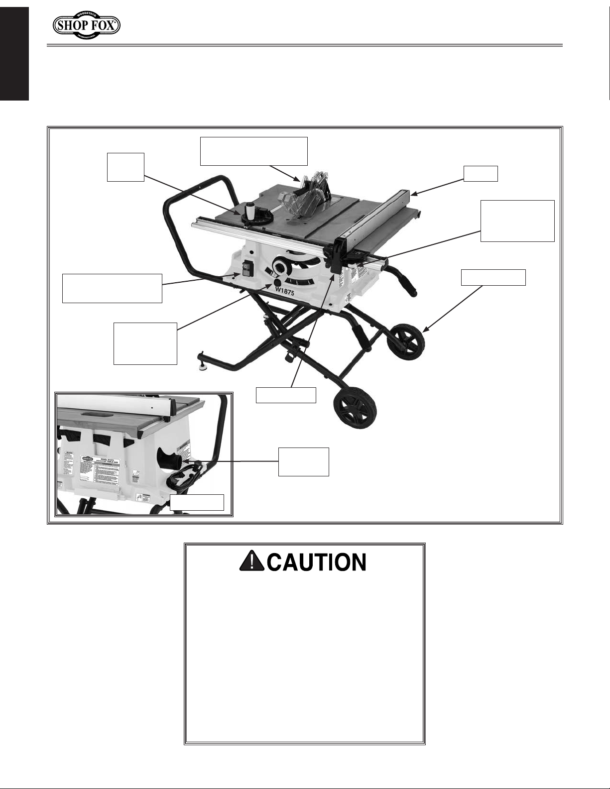
Become familiar with the names and locations of the controls and features shown below to better
Miter
Gauge
Model W1875 (For Machines Mfd. Since 1/20)
Identification
Blade Guard w/
Anti-Kickback Pawls
Fence
Fence
Micro-Adjust
Knob
ON/OFF
Push Button Switch
Blade
Height/Tilt
Handwheel
Roller Stand
Fence Lock
21⁄2"
Dust Port
Rear View
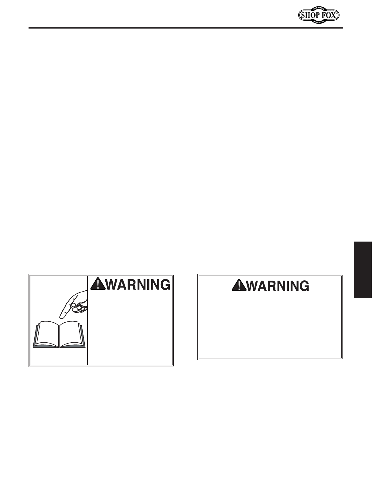
For Your Own Safety Read Instruction
Manual Before Operating Saw
a) Wear eye protection.
b) Use saw-blade guard and spreader for
every operation for which it can be
used, including all through sawing.
c) Keep hands out of the line of saw blade.
d) Use a push-stick when required.
e) Pay particular attention to instructions
on reducing risk of kickback.
f) Do not perform any operation freehand.
g) Never reach around or over saw blade.
-6-
Page 11
Model W1875 (For Machines Mfd. Since 1/20)
Controls & Components
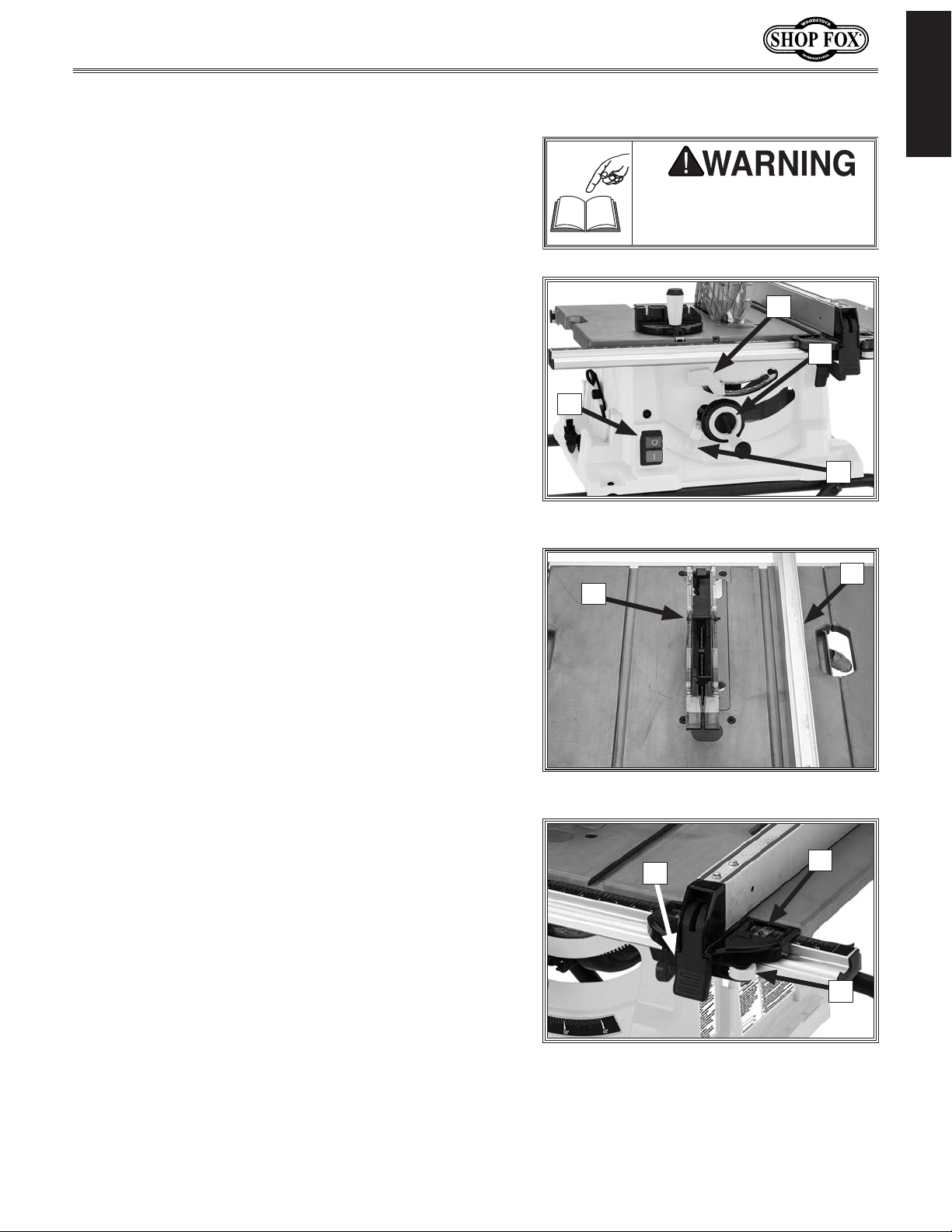
Refer to Figures 1–3 and the following descriptions to
become familiar with the basic controls and components
of this machine. Understanding these items and how they
work will help you understand the rest of the manual and
reduce your risk of injury when operating this machine.
A. ON/OFF Button Switch: Push ON button to start
motor. Push OFF button to stop motor.
B. Blade Tilt Lock Lever: Secures blade tilt setting.
Move right to unlock and allow blade tilt adjustment;
move left to secure setting.
INTRODUCTION
To reduce your risk of serious
injury, read this entire manual
BEFORE using machine.
B
C
C. Blade Height/Tilt Handwheel: Rotates to adjust
blade height from 0–3
blade; rotate counterclockwise to lower blade. Push
inward and rotate to angle blade from 0°–45°.
D. Blade Tilt Indicator: Indicates angle of blade from
0–45°.
E. Blade Guard w/Anti-Kickback Protection: Clear
guard helps to prevent hands and fingers from
contacting rotating blade. Anti-kickback pawls and
spreader reduce risk of kickback (for information on
kickback and how to prevent it, refer to Page 12).
F. Fence: Supports long edge of workpiece during rip
cuts. Refer to Page 33 for more information.
G. Fence Lock Lever: Locks fence position. Move up to
loosen fence; move down to lock fence.
H. Fence Scale & Pointer: Indicates distance from
fence to blade. Set to desired width of finished
workpiece.
1
⁄2". Rotate clockwise to raise
A
D
Figure 1. Power and blade controls.
F
E
Figure 2. Blade guard and fence.
H
G
I. Fence Micro-Adjust Knob: Rotates to finely adjust
distance between fence and blade.
-7-
I
Figure 3. Fence controls.
Page 12

Model W1875 (For Machines Mfd. Since 1/20)
Glossary of Terms
The following is a list of common definitions, terms and phrases used throughout this manual as they relate
INTRODUCTION
to this table saw and woodworking in general. Become familiar with these terms for assembling, adjusting
or operating this machine.
Arbor: A metal shaft extending from the drive
mechanism that is the mounting location
for the saw blade.
Bevel Edge Cut: A cut made with the blade
tilted to an angle between 0˚ and 45˚ to
cut a beveled edge onto a workpiece. Refer
Page 35 for more details.
to
Blade Guard Assembly: Metal or plastic safety
device that mounts over the saw blade. Its
function is to prevent the operator from
coming into contact with the saw blade.
Refer to
Crosscut: Cutting operation in which the miter
gauge is used to cut across the shortest
width of the workpiece. Refer to
for more details.
Dado Blade: Blade or set of blades that are
used to cut grooves, rabbets, or other nonthrough cuts. Refer to
details. The saw and arbor are not intended
to safely use a larger dado blade.
Dado Cut: Non-through cutting operation that
uses a dado blade to cut a flat bottomed
groove into the face of the workpiece.
Refer to
Featherboard: Safety device used to keep the
workpiece against the rip fence and against
the table surface. Refer to
more details.
Kerf: The resulting cut or gap in the workpiece
after the saw blade passes through during a
cutting operation.
Kickback:
propelled back towards the operator at a
high rate of speed.
Page 28 for more details.
Page 34
Page 26 for more
Page 36 for more details.
Page 41 for
An event in which the workpiece is
Non-Through Cut: A cut in which the blade
does not cut through the top of the
workpiece. Refer to
details.
Parallel: Being an equal distance apart at every
point along two given lines or planes (i.e.
the rip fence face is parallel to the face of
the saw blade).
Perpendicular: Lines or planes that intersect
and form right angles (i.e. the blade is
perpendicular to the table surface).
Push Stick: Safety device used to push the
workpiece through a cutting operation.
Used most often when rip cutting thin
workpieces. Refer to
details.
Rabbet: Non-through cutting operation that
creates an L-shaped channel along the edge
of the workpiece. Refer to
more details.
Rip Cut: Cutting operation in which the rip
fence is used to cut across the widest width
of the workpiece. Refer to
more details.
Riving Knife: Metal plate located behind the
blade. It maintains the kerf opening in the
wood when performing a cutting operation.
Refer to
Straightedge: A tool used to check the flatness,
parallelism, or consistency of a surface(s).
Thin Kerf Blade: A blade with a kerf or
thickness that is thinner than a standard
blade cannot be used on this saw without
using a thin-kerf riving knife.
Through Cut: A cut in which the blade cuts
completely through the workpiece. Refer to
Page 24 for more details.
Page 31 for more details.
Page 24 for more
Page 44 for more
Page 39 for
Page 33 for
-8-
Page 13
Model W1875 (For Machines Mfd. Since 1/20)
SAFETY
OWNER’S MANUAL.
TRAINED OPERATORS ONLY.
DANGEROUS ENVIRONMENTS.
MENTAL ALERTNESS REQUIRED.
electrical components or improperly grounded
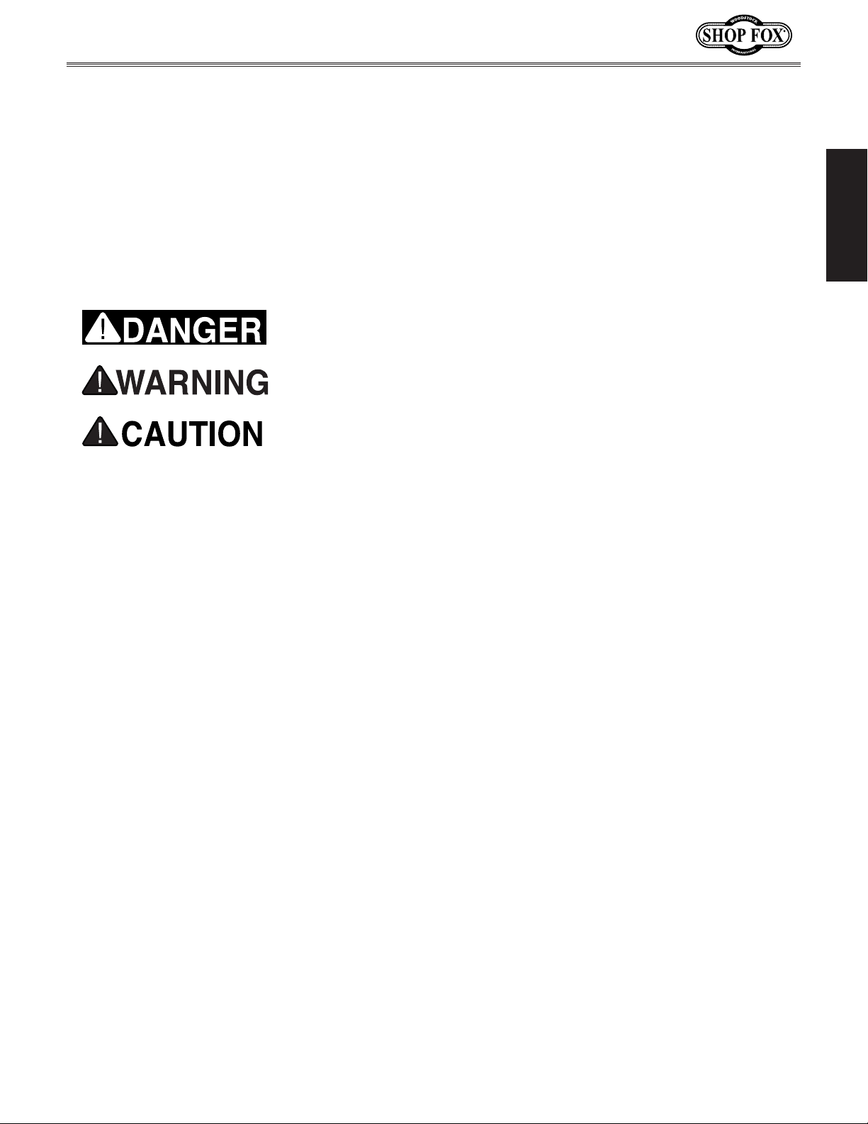
manual uses a series of symbols and signal words intended to convey the level of importance of the
safety messages. The progression of symbols is described below. Remember that safety messages by
SAFETY
For Your Own Safety,
Read Manual Before Operating Machine
The purpose of safety symbols is to attract your attention to possible hazardous conditions. This
themselves do not eliminate danger and are not a substitute for proper accident prevention measures—this responsibility is ultimately up to the operator!
NOTICE
Standard Machinery Safety Instructions
Standard Machinery Safety Instructions
Indicates an imminently hazardous situation which, if not avoided,
WILL result in death or serious injury.
Indicates a potentially hazardous situation which, if not avoided,
COULD result in death or serious injury.
Indicates a potentially hazardous situation which, if not avoided,
MAY result in minor or moderate injury.
This symbol is used to alert the user to useful information about
proper operation of the equipment or a situation that may cause
damage to the machinery.
SAFETY
Read and understand this
owner’s manual BEFORE using machine.
have a higher risk of being hurt or killed. Only
allow trained/supervised people to use this
machine. When machine is not being used,
disconnect power, remove switch keys, or
lock-out machine to prevent unauthorized
use—especially around children. Make
workshop kid proof!
machinery in areas that are wet, cluttered,
or have poor lighting. Operating machinery
in these areas greatly increases the risk of
accidents and injury.
alertness is required for safe operation of
machinery. Never operate under the influence
of drugs or alcohol, when tired, or when
distracted.
Untrained operators
Do not use
Full mental
ELECTRICAL EQUIPMENT INJURY RISKS. You can
be shocked, burned, or killed by touching live
machinery. To reduce this risk, only allow an
electrician or qualified service personnel to
do electrical installation or repair work, and
always disconnect power before accessing or
exposing electrical equipment.
DISCONNECT POWER FIRST. Always disconnect
machine from power supply BEFORE making
adjustments, changing tooling, or servicing
machine. This eliminates the risk of injury
from unintended startup or contact with live
electrical components.
EYE PROTECTION. Always wear ANSI-approved
safety glasses or a face shield when operating
or observing machinery to reduce the risk of
eye injury or blindness from flying particles.
Everyday eyeglasses are not approved safety
glasses.
-9-
Page 14

WEARING PROPER APPAREL. Do not wear
clothing, apparel, or jewelry that can become
HAZARDOUS
HEARING PROTECTION.
REMOVE ADJUSTING TOOLS.
INTENDED USAGE.
AWKWARD POSITIONS.
CHILDREN & BYSTANDERS.
GUARDS & COVERS.
FORCING MACHINERY. Do not force machine. It
will do the job safer and better at the rate for
loss of control. Before starting, verify machine
malfunction, leading to serious personal injury
from heated surfaces, high traffic areas, harsh
entangled in moving parts. Always tie back
or cover long hair. Wear non-slip footwear to
avoid accidental slips, which could cause loss
of workpiece control.
DUST. Dust created while using
SAFETY
machinery may cause cancer, birth defects,
or long-term respiratory damage. Be aware of
dust hazards associated with each workpiece
material, and always wear a NIOSH-approved
respirator to reduce your risk.
Always wear hearing
protection when operating or observing
loud machinery. Extended exposure to this
noise without hearing protection can cause
permanent hearing loss.
Tools left on
machinery can become dangerous projectiles
upon startup. Never leave chuck keys,
wrenches, or any other tools on machine.
Always verify removal before starting!
Only use machine for its
intended purpose—never make modifications
without prior approval from Woodstock
International. Modifying machine or using
it differently than intended will void the
warranty and may result in malfunction or
mechanical failure that leads to serious
personal injury or death!
Keep proper footing and
balance at all times when operating machine.
Do not overreach! Avoid awkward hand
positions that make workpiece control difficult
or increase the risk of accidental injury.
Keep children and
bystanders at a safe distance from the work
area. Stop using machine if they become a
distraction.
Model W1875 (For Machines Mfd. Since 1/20)
which it was designed.
NEVER STAND ON MACHINE. Serious injury may
occur if machine is tipped or if the cutting
tool is unintentionally contacted.
STABLE MACHINE. Unexpected movement during
operation greatly increases risk of injury or
is stable and mobile base (if used) is locked.
USE RECOMMENDED ACCESSORIES. Consult
this owner’s manual or the manufacturer for
recommended accessories. Using improper
accessories will increase risk of serious injury.
UNATTENDED OPERATION. To reduce the risk
of accidental injury, turn machine OFF and
ensure all moving parts completely stop
before walking away. Never leave machine
running while unattended.
MAINTAIN WITH CARE. Follow all maintenance
instructions and lubrication schedules to
keep machine in good working condition. A
machine that is improperly maintained could
or death.
CHECK DAMAGED PARTS. Regularly inspect
machine for any condition that may affect
safe operation. Immediately repair or replace
damaged or mis-adjusted parts before
operating machine.
MAINTAIN POWER CORDS. When disconnecting
cord-connected machines from power, grab
and pull the plug—NOT the cord. Pulling the
cord may damage the wires inside, resulting
in a short. Do not handle cord/plug with wet
hands. Avoid cord damage by keeping it away
chemicals, and wet/damp locations.
accidental contact with moving parts or flying
debris—make sure they are properly installed,
undamaged, and working correctly.
Guards and covers reduce
EXPERIENCING DIFFICULTIES. If at any time
you experience difficulties performing the
intended operation, stop using the machine!
-10-
Contact Technical Support at (360) 734-3482.
Page 15

Model W1875 (For Machines Mfd. Since 1/20)
Serious cuts, amputation, or death can occur from contact with rotating saw blade during operation. Workpieces, broken blades, or flying particles thrown by blade can blind or strike operators or
bystanders with deadly force. To reduce the risk of these hazards, operator and bystanders MUST
completely heed the hazards and warnings below.
Make sure blade
Damaged saw blade teeth
Never use blades
risk of operator
HAND & BODY POSITIONING
BLADE GUARD.
RIVING KNIFE.
KICKBACK.
FEEDING WORKPIECE
D
Additional Safety for Table Saws
from saw blade and out of blade path during
operation, so they cannot accidentally slip into
blade. Only operate at front of machine and
always stand to side of blade path. Never reach
behind or over blade, or under blade guard
when blade is spinning.
The blade guard protects operator
from rotating saw blade. Make sure blade guard
is installed, adjusted correctly, and used for
all possible “through cuts.” Promptly repair or
replace if damaged. Re-install immediately after
operations that require its removal.
Use riving knife for all “nonthrough cuts.” Make sure it is aligned and positioned correctly. Promptly repair or replace it if
damaged.
. Keep hands away
PUSH STICKS/PUSH BLOCKS. To reduce risk of
accidental blade contact, use push sticks/push
blocks whenever possible. In event of an accident, these will often take damage that would
have occurred to hands/fingers.
FENCE. To reduce risk of kickback, make sure
fence remains properly adjusted and parallel
with blade. Always lock fence before using. Do
not use fence while using miter gauge. Make
sure fence is not touching the blade when the
saw is started.
CUT-OFF PIECES. To avoid risk of injury due to
blade contact, turn saw OFF and allow blade to
completely stop before removing cut-off pieces
near blade or trapped between blade and table
insert. Never use your hands to move cut-of f
pieces away from blade while saw is running.
SAFETY
workpiece back toward operator. Know how to
reduce risk of kickback, and learn how to protect yourself if it does occur.
rectly increases risk of kickback. Always allow
blade to reach full speed before cutting, feed
workpiece from front of saw, making sure workpiece is flat against table and a fence, miter
gauge, or other guide is used to feed workpiece
in a straight line. Feed cuts through to completion. Never start saw with workpiece touching
blade or pull workpiece from behind blade.
Never back workpiece out of cut, move it sideways, or perform a “freehand” operation. Never
plunge cut.
ADO AND RABBET OPERATIONS. Dado and rab-
beting operations require special attention
since they must be performed with blade guard
removed, which increases risk of blade contact.
DO NOT attempt dado or rabbeting operations
without first reading these sections in this manual.
Kickback occurs when saw blade ejects
. Feeding workpiece incor-
BLADE ADJUSTMENTS. Adjusting blade height or
tilt during operation increases risk of crashing
blade and sending metal fragments flying with
deadly force at operator or bystanders. Only
adjust blade height and tilt when blade is completely stopped and saw is O F F.
is not touching the guard, riving knife, or workpiece before the saw is started.
CHANGING BLADES. Accidental startup while
changing saw blade can result in serious injury.
To reduce risk of accidental blade contact,
always disconnect power before changing
blades.
DAMAGED SAW BLADES.
can become deadly projectiles.
that have been dropped or damaged.
CUTTING CORRECT MATERIAL. Cutting metal,
glass, stone, tile, etc., increases
injury due to kickback or flying particles. Only
cut natural and man-made wood products, laminatecovered wood products, and some plastics.
Never cut materials not intended for this saw.
-11-
Page 16
Preventing Kickback
Below are ways to avoid the most common
causes of kickback:
• Only cut workpieces with at least one smooth
and straight edge. DO NOT cut warped,
cupped or twisted wood.
SAFETY
• Keep the blade guard installed and working
correctly for all through cuts.
Model W1875 (For Machines Mfd. Since 1/20)
• Never move the workpiece backwards or
try to back it out of a cut while the blade
is moving. If you cannot complete a cut for
some reason, stop the saw motor and allow
the blade to completely stop before backing
the workpiece out. Promptly fix the condition
that prevented you from completing the cut
before starting the saw again.
Protecting Yourself
• Never attempt freehand cuts. If the
workpiece is not fed parallel with the blade,
kickback will likely occur. Always use the rip
fence or miter gauge to guide the workpiece.
• Make sure the spreader or riving knife is
aligned with the blade and secured tightly. A
misaligned spreader or riving knife can cause
the workpiece to catch or bind, increasing
the chance of kickback.
• Take the time to check and adjust the rip
fence parallel with the blade; otherwise, the
chances of kickback are extreme.
• The spreader or riving knife maintains the
kerf in the workpiece, reducing the chance of
kickback. Always use the riving knife for all
non-through operations, unless a dado blade
is installed. Always use the spreader with the
blade guard for all through cuts.
• Feed cuts through to completion. Anytime
you stop feeding a workpiece in the middle
of a cut, the chance of kickback is greatly
increased.
• Keep the blade guard installed and in good
working order. Only remove it when performing
non-through cuts and immediately re-install
the blade guard when finished. Remember,
always use the riving knife for all non-through
operations, unless a dado blade is installed.
• Make multiple, shallow passes when performing a non-through cut. Making a deep nonthrough cut will greatly increase the chance of
kickback.
From Kickback
Even if you know how to prevent kickback, it
may still happen. Here are some ways to protect
yourself if kickback DOES occur:
• Stand to the side of the blade during every
cut. If kickback does occur, the thrown
workpiece usually travels directly in front of
the blade.
• Wear safety glasses or a face shield. In the
event of kickback, your eyes and face are the
most vulnerable parts of your body.
• Never, for any reason, place your hand behind
the blade. Should kickback occur, your hand
will be pulled into the blade, which could
cause amputation.
• Use a push stick to keep your hands farther
away from the moving blade. If kickback
occurs, the push stick will most likely take
the damage your hand would have received.
• Use featherboards or anti-kickback devices to
assist with feeding and prevent or slow down
kickback.
Statistics show that most common accidents
among table saw users can be linked to
kickback. Kickback is typically defined as the
high-speed expulsion of stock from the table
saw toward its operator. In addition to the
danger of the operator or others in the area
being struck by the flying stock, it is often the
case that the operator’s hands are pulled into
the blade during kickback.
-12-
Page 17
Model W1875 (For Machines Mfd. Since 1/20)
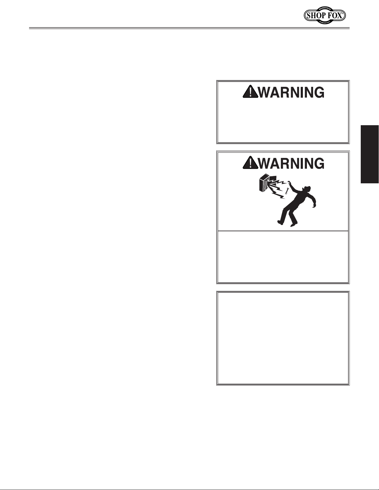
This machine must be connected to the correct size and
type of power supply circuit, or fire or electrical damage
may occur. Read through this section to determine if an
adequate power supply circuit is available. If a correct
circuit is not available, a qualified electrician MUST install
one before you can connect the machine to power.
A power supply circuit includes all electrical equipment
between the breaker box or fuse panel in the building
and the machine. The power supply circuit used for
this machine must be sized to safely handle the fullload current drawn from the machine for an extended
period of time. (If this machine is connected to a circuit
protected by fuses, use a time delay fuse marked D.)
This machine is prewired to operate on a power supply
circuit that has a verified ground and meets the following
requirements:
The full-load current rating is the amperage a machine
draws at 100% of the rated output power. On machines
with multiple motors, this is the amperage drawn by the
largest motor or sum of all motors and electrical devices
that might operate at one time during normal operations.
or machine damage. To reduce this risk,
where only one machine will be running
multiple machines will be running at the
ELECTRICAL
Circuit Requirements
The machine must be properly set up
before it is safe to operate. DO NOT
connect this machine to the power
source until instructed to do so later
in this manual.
ELECTRICAL
Full-Load Current Rating
Full-Load Current Rating at 120V .................. 15 Amps
Circuit Requirements for 120V
Circuit Type ............... 110V/120V, 60 Hz, Single-Phase
Circuit Size ............................................. 20 Amps
Plug/Receptacle .................................... NEMA 1-15
Incorrectly wiring or grounding this
machine can cause electrocution, fire,
only an electrician or qualified service
personnel should do any required
electrical work on this machine.
NOTICE
The circuit requirements listed in this
manual apply to a dedicated circuit—
at a time. If this machine will be
connected to a shared circuit where
same time, consult with an electrician
to ensure that the circuit is properly
sized for safe operation.
-13-
Page 18
When using extension cords, make sure the cords are
rated for outdoor use. Outdoor use cords are marked with
a “W-A” or a “W” to signify their rating. Always check to
indicate smaller sizes. When using extension cords, always
choose the shortest cord possible, with the greatest-sized
running this tool at different lengths:
Polarized Plug
This tool is double-insulated and therefore does not have
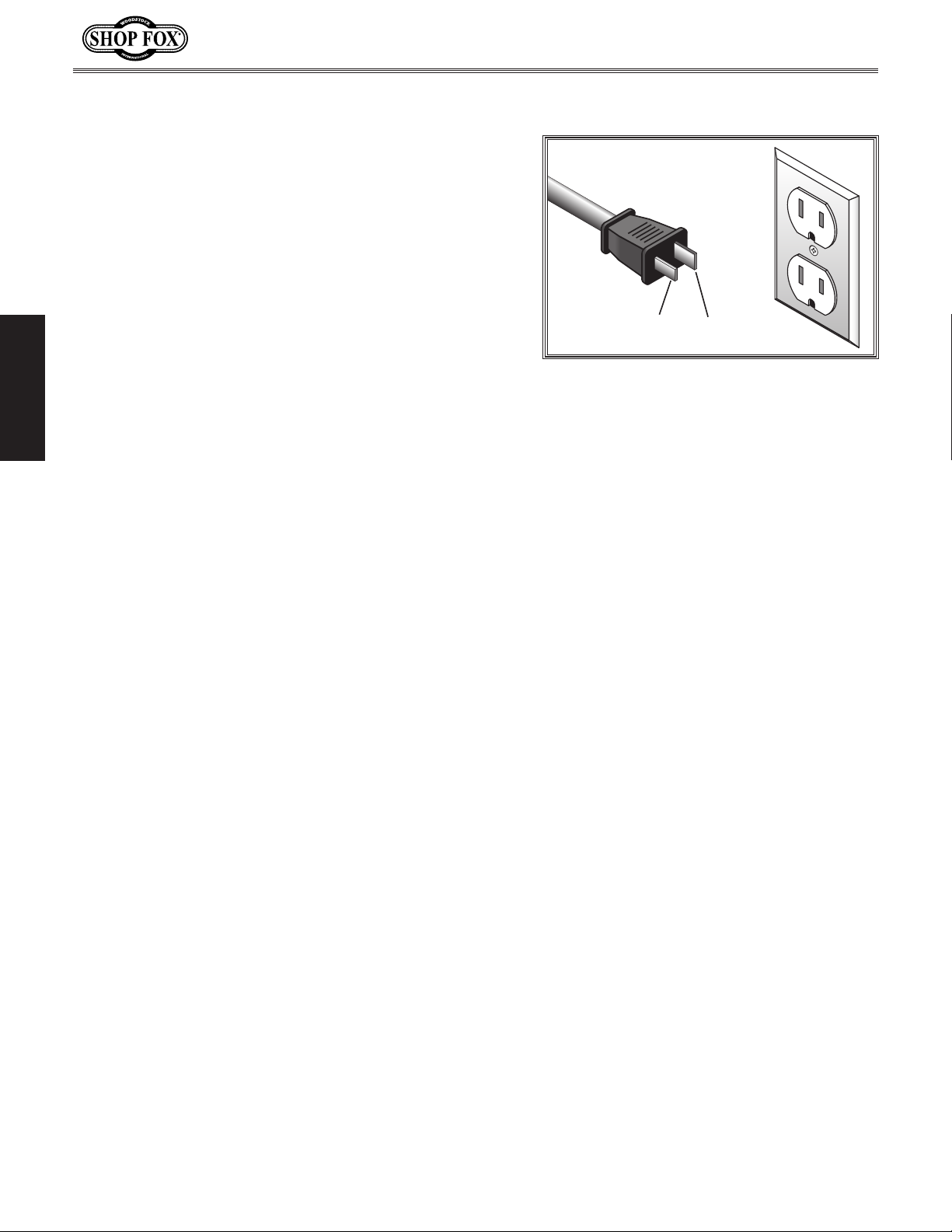
a grounding wire or plug. The two-pronged, NEMA 1-15
plug has a polarized end; this means that one prong
(the neutral connector) is wider than the other (the
hot connector). Polarized plugs must be used only with
polarized receptacles. Do not attempt to plug this tool
into a non-polarized receptacle. If a polarized receptacle
is not available, a qualified electrical technician will have
to install one before the saw can be plugged in.
Model W1875 (For Machines Mfd. Since 1/20)
5-15 Receptacle
1-15 Plug
Hot
Neutral
Extension Cords
ELECTRICAL
make sure that the extension cords are in good working
order and free of any type of damage, such as exposed
wires, cuts, creased bends, or missing prongs.
Extension cords cause voltage drop, which may damage
electrical components and shorten motor life. Voltage
drop increases as the extension cord size gets longer
and the gauge size gets smaller (higher gauge numbers
gauge.
Below is a list of minimum gauge sizes needed for
Minimum Gauge Size at 120V ...................... 12 AWG
Maximum Length (Shorter is Better) ................50 ft.
Figure 4. NEMA 1-15 plug & receptacle.
-14-
Page 19
Model W1875 (For Machines Mfd. Since 1/20)
This machine has been carefully packaged for safe
transportation. If you notice the machine has been
damaged during shipping, please contact your authorized
Shop Fox dealer immediately.
The following items are needed, but not included, to set
up your machine.
This machine presents
serious injury hazards
to untrained users. Read
to become familiar with
tions before starting the
SETUP
Unpacking
through this entire manual
the controls and opera-
Items Needed for Setup
Description Qty
• An Assistant .................................................1
• Safety Glasses for Each Person ..........................1
• Wrench or Socket 13mm .................................1
• Hex Wrench 3mm ..........................................1
• Straightedge ................................................1
• Dust Collection System ...................................1
• Dust Hose 21⁄2" .............................................1
• Hose Clamps 21⁄2" .........................................2
machine!
Wear safety glasses during
entire setup process!
SETUP
USE helpers or power
lifting equipment to lift
this machine. Otherwise,
serious personal injury
may occur.
-15-
Page 20
Model W1875 (For Machines Mfd. Since 1/20)
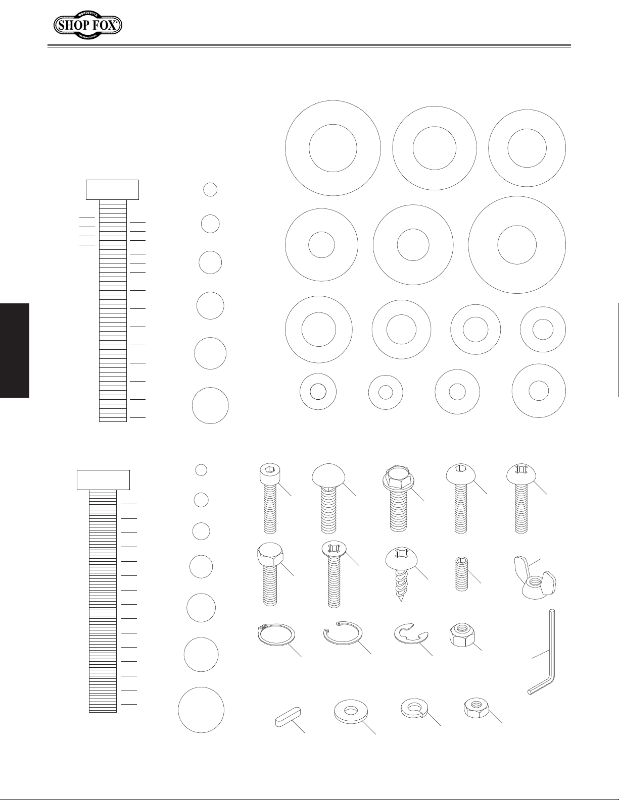
Hardware Recognition Chart
USE THIS CHART TO IDENTIFY
D
I
A
R
5
⁄8"
M
E
T
E
R
HARDWARE DURING THE
INVENTORY/ASSEMBLY
PROCESS.
A
W
E
H
S
#10
1
⁄4"
3
⁄8"
1
⁄2"
5
⁄8"
5
⁄16"
7
⁄16"
9
⁄16"
3
⁄4"
7
⁄8"
1
⁄4"
5
⁄16"
R
E
H
8mm
S
A
D
I
A
M
E
T
E
R
W
R
E
H
S
10mm
A
W
1
1
1
⁄4"
1
1
⁄2"
3
⁄4"
1
2
⁄16" INCH APART
1
SETUP
LINES ARE
1
2
⁄4"
1
2
⁄2"
3
2
⁄4"
3
3
⁄8"
7
⁄16"
1
⁄2"
D
I
A
R
E
7
R
E
H
S
A
#10
⁄16"
D
I
A
W
M
E
T
E
R
M
E
T
E
R
E
H
S
A
D
R
E
H
S
A
W
4mm
H
S
A
W
WASHERS ARE MEASURED BY THE INSIDE DIAMETER
R
W
I
A
R
3
⁄8"
M
E
T
E
D
D
I
A
R
A
E
T
9
⁄16"
M
E
T
E
R
M
E
T
E
R
H
S
A
A
I
D
M
R
E
E
H
S
D
I
R
E
H
S
A
W
5
A
A
M
E
R
⁄16"
W
E
T
T
E
R
E
H
S
A
W
D
I
I
A
M
E
R
5mm
E
H
S
A
W
R
E
12mm
W
R
D
1
⁄2"
I
D
I
A
A
M
E
R
E
H
1
S
A
W
D
R
E
H
S
A
W
6mm
M
T
E
R
D
I
⁄4"
I
A
R
E
T
E
R
A
M
E
T
E
R
M
E
T
E
5mm
10mm
15mm
20mm
25mm
30mm
35mm
MEASURE BOLT DIAMETER BY PLACING INSIDE CIRCLE
40mm
45mm
50mm
55mm
LINES ARE 1MM APART
60mm
65mm
70mm
75mm
4mm
5mm
6mm
8mm
10mm
12mm
16mm
Cap
Screw
Hex
Bolt
External
Retaining
Ring
Key
Carriage
Bolt
Flat
Head
Screw
Internal
Retaining
Ring
Flat Washer
Flange
Bolt
Tap
Screw
E-Clip
Lock
Washer
Button
Head
Screw
Set
Screw
Lock
Nut
Hex
Nut
Phillips
Head
Screw
Wing
Nut
Hex
Wrench
-16-
Page 21
Model W1875 (For Machines Mfd. Since 1/20)
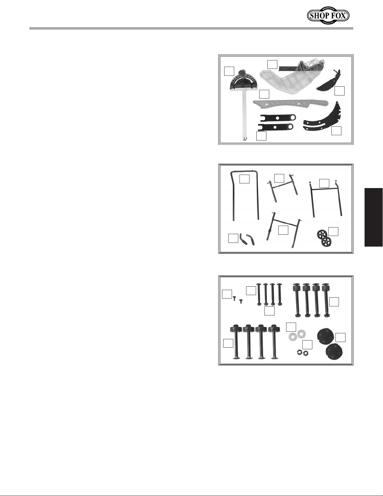
The following is a list of items shipped with your machine.
Before beginning setup, lay these items out and inventory
them.
Note:
check around/inside the machine and packaging materials.
Often, these items get lost in packaging materials while
unpacking or they are pre-installed at the factory.
Inventory
C
B
If you cannot find an item on this list, carefully
Table Saw Inventory (Figure 5) Qty
A. Main Table Saw Unit (Not Shown) .......................1
B. Miter Gauge ................................................1
Blade Guard ................................................1
C.
D. Push Stick ...................................................1
E. Anti-Kickback Pawls .......................................1
Arbor Wrenches ............................................2
F.
Spreader/Riving Knife ....................................1
G.
Dado Insert (Not Shown) .................................1
H.
Stand Inventory (Figure 6) Qty
U-Bracket ...................................................1
I.
Middle Bracket .............................................1
J.
Foot Bracket................................................1
K.
Handles ......................................................2
L.
Wheel Bracket .............................................1
M.
8" Wheels ...................................................2
N.
D
F
Figure 5. Table saw inventory.
I
L
Figure 6. Stand inventory.
J
M
E
G
K
SETUP
N
Stand Hardware (Figure 7) Qty
O. Tap Screws M5 x 10 .......................................2
Button Head Cap Screws M6-1 x 55 (Machine) ........4
P.
Lock Nuts M6-1 (Machine) ................................4
Q.
Middle Bracket Fasteners
R.
— Carriage Bolts M8-1.25 x 40 ...........................4
— Spacers ....................................................4
— Lock Nuts M8-1.25 ......................................4
Foot Bracket Fasteners
S.
— Carriage Bolts M8-1.25 x 40 ...........................4
— Spacers ....................................................4
— Lock Nuts M8-1.25 ......................................4
Fender Washers 8mm (Wheel) ...........................2
T.
Lock Nuts M8-1.25 (Wheel) ..............................2
U.
Wheel Caps .................................................2
V.
O
S
P
R
Q
T
V
U
Figure 7. Stand hardware.
-17-
Page 22
Machine Placement
Refer to the Machine Specifications for the
weight and footprint specifications of your
machine. Some workbenches may require
additional reinforcement to support the weight
of the machine and workpiece materials.
Consider anticipated workpiece sizes and
additional space needed for auxiliary stands,
work tables, or other machinery when
establishing a location for this machine in the
shop. Below is the minimum amount of space
needed for the machine.
users can injure themselves
Before beginning the assembly process, refer to Items
Needed for Setup
Ensure all parts have been properly cleaned of any
heavy-duty rust-preventative applied at the factory (if
applicable). Be sure to complete all steps in the assembly
procedure prior to performing the
or connecting
the machine to power.
Workbench Load
Model W1875 (For Machines Mfd. Since 1/20)
1
⁄2"
28
Placement Location
SETUP
Assembly
and gather everything you need.
57"
= Power Connection
Figure 8. Minimum working clearances.
INJURY HAZARD! Untrained
with this machine. Restrict
access to machine when
you are away, especially if
it is installed where children are present.
U-Bracket
x 2
Test Run
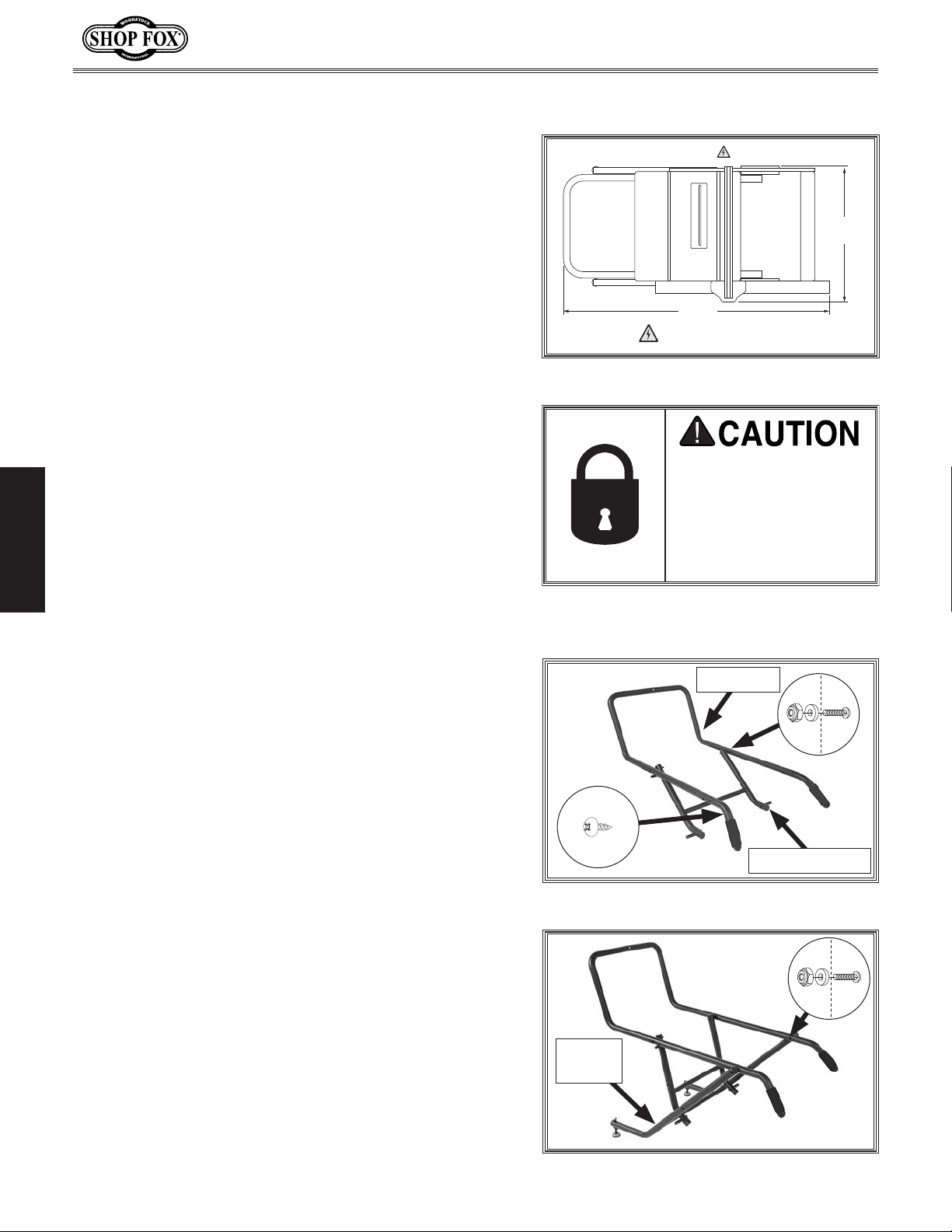
To assemble stand and mount saw, do these steps:
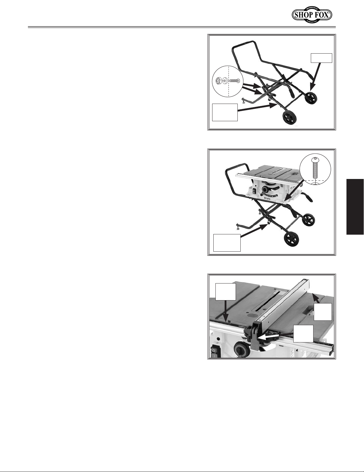
1. Attach each handle to U-bracket with M5 x 10 tap
screw (see
2. Attach middle bracket to U-bracket with (2) M8-1.25
x 40 carriage bolts, (2) spacers, and (2) M8-1.25 lock
nuts (see Figure
3. Attach foot bracket to U-bracket with (2) M8-1.25 x
40 carriage bolts, (2) spacers, and (2) M8-1.25 lock
nuts (see
Figure 9).
9).
Figure 10).
x 2
Middle Bracket
Figure 9. U-bracket assembly.
x 2
Foot
Bracket
Figure 10. Foot bracket assembly.
-18-
Page 23
Model W1875 (For Machines Mfd. Since 1/20)
4. Attach wheel bracket to middle bracket with (2)
M8-1.25 x 40 carriage bolts, (2) spacers, and (2)
M8-1.25 lock nuts (see
Figure 11).
Wheel
5. Attach wheel bracket to foot bracket with (2)
M8-1.25 x 40 carriage bolts, (2) spacers, and (2)
M8-1.25 lock nuts (see
6. Remove wheel cap from stand and mounting
hardware from wheels. Attach each wheel to
wheel bracket with (2) 8mm fender washers and
(2) M8-1.25 lock nuts, then replace wheel cap (see
Figure 11).
7
. Push release latch (see Figure 12) and pull handles
up until release latch clicks, locking the stand.
. Place table saw on stand and secure with (4) M6-1
8
x 55 button head cap screws and (4) M6-1 lock nuts
Figure 12).
(see
Note: Full extension of extension wing requires
table saw be oriented on stand as shown in Figure
12.
Figure 11).
x 4
Wheel
Bracket
Figure 11. Wheel bracket assembly.
x 4
SETUP
Release
Latch
9. Place fence on front rail, then lower back of fence
onto rear rail. Lower lock lever to secure and align
fence (see
Figure 13).
Figure 12. Table saw mounted on stand.
Front
Rail
Rear
Rail
Lock
Lever
Figure 13. Fence in position on table.
-19-
Page 24
Do not confuse this CFM recommendation with the rating
of the dust collector. To determine the CFM at the dust
port, you must consider these variables: (1) CFM rating of
the dust collector, (2) hose type and length between the
dust collector and the machine, (3) number of branches
or wyes, and (4) amount of other open lines throughout
the system. Explaining how to calculate these variables
is beyond the scope of this manual. Consult an expert or
purchase a good dust collection “how-to” book.
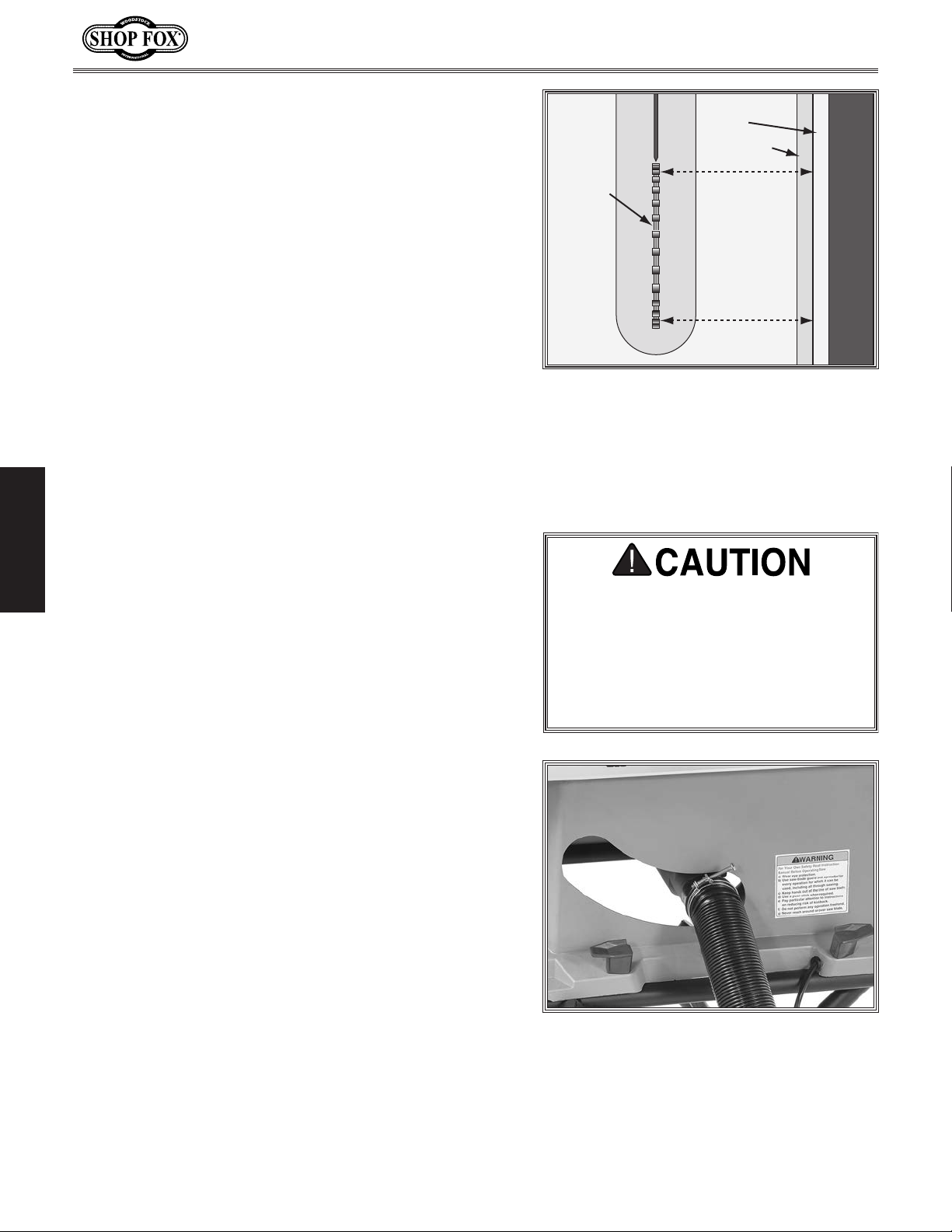
10. Slide fence up against right hand edge of miter slot,
and lock it in place. Examine how fence lines up
with miter slot (see
Figure 14).
Model W1875 (For Machines Mfd. Since 1/20)
Fence
Miter Slot
Note: It is permissible for back of fence to pivot
1
outward not more than
⁄64" from being parallel with
miter slot. This creates a slightly larger opening
between fence and blade, at rear of blade, to
reduce risk of workpiece binding or burning as it is
fed through cut. Many woodworkers intentionally
set up their fence in this manner. Keep this in mind
before adjusting your fence. For more details refer
to Offsetting Fence on Page 55.
— If fence is still parallel with miter slot, proceed to
Step 11.
— If fence is not parallel with miter slot, then
you MUST adjust fence so that it is parallel, as
described in
Calibrating Fence to Blade on Page
55.
If miter slot is not parallel with blade, you must
—
SETUP
follow procedures described in
Miter Slot to Blade
Parallelism on Page 50.
Install blade guard as instructed on Page 28.
11.
Dust Collection
Recommended CFM at Dust Port: ................ 150 CFM
Blade
Fence is
Parallel to
Miter Slot,
which is
Parallel to
Blade
Figure 14. Checking fence parallelism with
blade.
This machine creates substantial
amounts of dust during operation.
Breathing airborne dust on a regular
basis can result in permanent respiratory illness. Reduce your risk by wearing a respirator and capturing the dust
with a dust collection system.
Tools Needed Qty
Dust Collection System
1
Dust Hose 2
Hose Clamps 2
⁄2" ..................................................1
1
⁄2" ...............................................2
........................................1
To connect a dust collection hose, do these steps:
1. Fit a 21⁄2" dust hose over the dust port, as shown in
Figure 15, and secure it in place with a hose clamp.
-20-
Figure 15. Dust port connected to dust
collection system.
Tug the hose to make sure it does not
2.
come off.
Note: A tight fit is necessary for
proper performance.
Page 25
Model W1875 (For Machines Mfd. Since 1/20)
performed. Operating an improperly set
Once assembly is complete, test run the machine to
ensure it is properly connected to power and safety
components are functioning properly.
If you find an unusual problem during the test run,
immediately stop the machine, disconnect it from power,
and fix the problem BEFORE operating the machine again.
The
section of this
manual can help.
Test Run
Troubleshooting table in the SERVICE
The Test Run consists of verifying the following: 1) The
motor powers up and runs correctly.
Serious injury or death can result
from using this machine BEFORE
understanding its controls and related
safety information. DO NOT operate, or
allow others to operate, machine until
the information is understood.
To test run machine, do these steps:
1. Clear all setup tools away from machine.
2. Connect machine to power supply.
3. Turn machine ON, verify motor operation, then turn
machine OFF.
The motor should run smoothly and without unusual
noises.
DO NOT start machine until all
preceding setup instructions have been
up machine may result in malfunction
or unexpected results that can lead
to serious injury, death, or machine/
property damage.
SETUP
-21-
Page 26
OPERATIONS
This machine will perform many types of operations
that are beyond the scope of this manual. Many of these
operations can be dangerous or deadly if performed
incorrectly.
The instructions in this section are written with the
understanding that the operator has the necessary
knowledge and skills to operate this machine. If at any
time you are experiencing difficulties performing any
operation, stop using the machine!
The overview below provides the novice machine operator
with a basic understanding of how the machine is used
during operation, so the machine controls/components
discussed later in this manual are easier to understand.
Due to its generic nature, this overview is
to be an instructional guide.
General
Model W1875 (For Machines Mfd. Since 1/20)
To reduce your risk of serious injury
or damage to the machine, read this
entire manual BEFORE using machine.
NOT intended
To complete a typical operation, the operator does the
following:
Examines workpiece to make sure it is suitable for
1.
cutting.
Adjusts blade tilt, if necessary, to correct angle for
2.
desired cut.
OPERATIONS
Adjusts blade height no more than 1⁄4" higher than
3.
thickness of workpiece.
Adjusts fence to desired width of cut, then locks it
4.
in place.
Checks outfeed side of machine for proper support
5.
and to make sure workpiece can safely pass all the
way through blade without interference.
Puts on safety glasses, respirator, and hearing
6.
protection, and locates push sticks/blocks if needed.
Starts saw.
7.
8. Feeds workpiece all the way through blade while
maintaining firm pressure on workpiece against table
and fence, and keeping hands and fingers out of
blade path and away from blade.
Stops machine immediately after cut is complete.
9.
To reduce the risk of eye injury and
long-term respiratory damage, always
wear safety glasses and a respirator
while operating this machine.
If you are an inexperienced operator,
we strongly recommend that you read
books or trade articles, or seek training
from an experienced operator of this
type of machinery before performing
unfamiliar operations. Above all, safety
must come first!
-22-
Page 27
Model W1875 (For Machines Mfd. Since 1/20)
Workpiece Inspection
Some workpieces are not safe to cut or may
require modification before they can be made
safe to cut.
Before cutting, get in the habit of inspecting
all workpieces for the following:
• Material Type: This machine is intended
for cutting natural and man-made wood
products, laminate covered wood products,
and some plastics. Cutting drywall or
cementitious backer board creates
extremely fine dust and may reduce the
life of the bearings. This machine is NOT
designed to cut metal, glass, stone, tile,
etc.; cutting these materials with a table
saw may lead to injury.
• Foreign Objects: Nails, staples, dirt,
rocks and other foreign objects are often
embedded in wood. While cutting, these
objects can become dislodged and hit the
operator, cause kickback, or break the
blade, which might then fly apart. Always
visually inspect your workpiece for these
items. If they can't be removed, DO NOT
cut the workpiece.
• Large/Loose Knots: Loose knots can
become dislodged during the cutting
operation. Large knots can cause kickback
and machine damage. Choose workpieces
that do not have large/loose knots or plan
ahead to avoid cutting through them.
• Wet or "Green" Stock: Cutting wood
with a moisture content over 20% causes
unnecessary wear on the blades, increases
the risk of kickback, yields poor results.
• Excessive Warping: Workpieces with
excessive cupping, bowing, or twisting are
dangerous to cut because they are unstable
and often unpredictable when being
cut. DO NOT use workpieces with these
characteristics!
• Minor Warping: Workpieces with slight
cupping can be safely supported if the
cupped side is facing the table or the
fence. On the contrary, a workpiece
supported on the bowed side will rock
during a cut and could cause kickback or
severe injury.
OPERATIONS
READ and understand this
entire manual before using
this machine. Serious personal injury may occur
if safety and operational
information is not understood and followed. DO
NOT risk your safety by
not reading!
USE this and other machinery with caution
and respect. Always consider safety first,
as it applies to your individual working
conditions. No list of safety guidelines can
be complete—every shop environment is
different. Failure to follow guidelines could
result in serious personal injury, damage to
equipment or poor work results.
-23-
Page 28
Non-Through
& Through Cuts
Non-Through Cuts
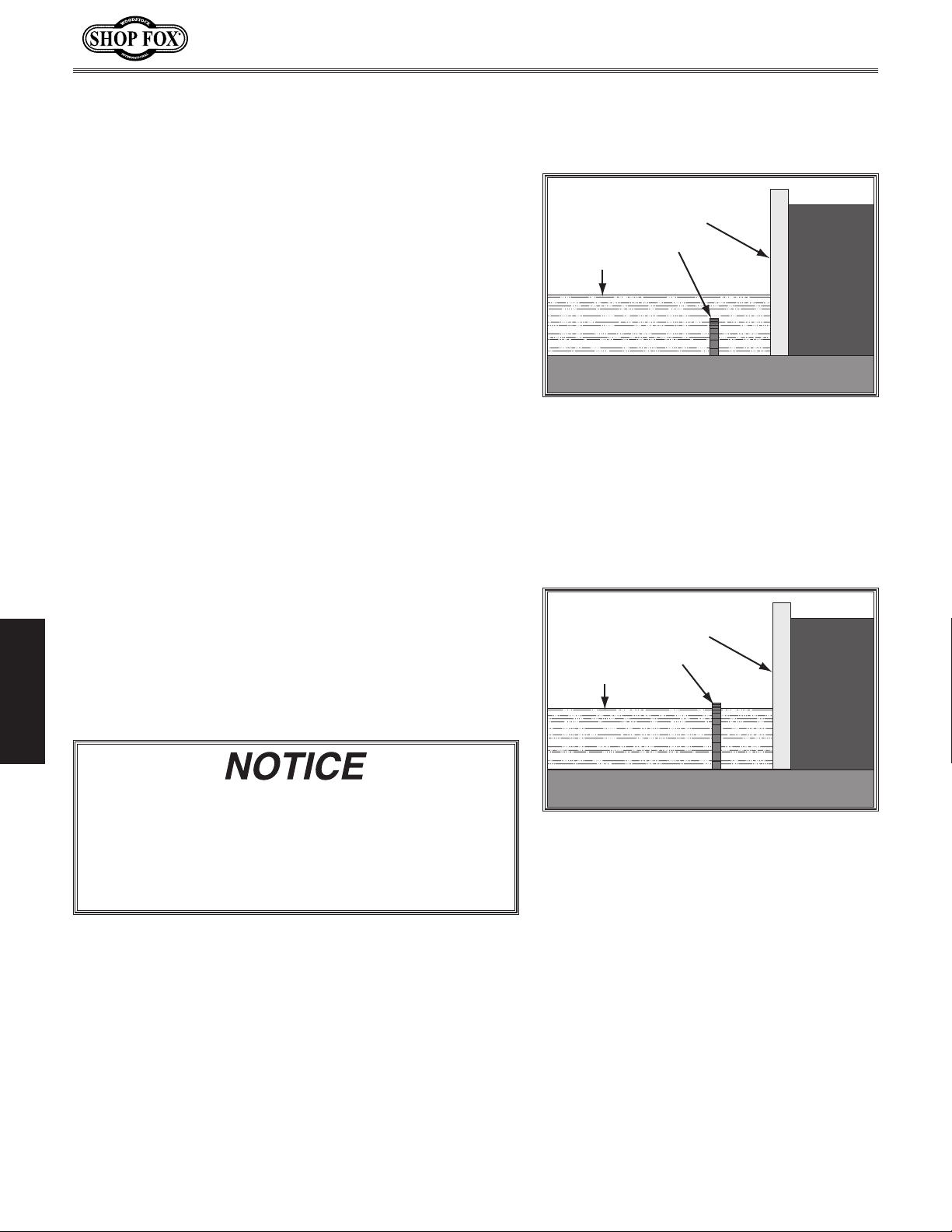
A non-through cut is a sawing operation where the blade
does not protrude above the top face of the wood stock,
as shown in
Examples of non-through cuts include dadoes and
rabbets. Non-through cuts have a higher risk of injury
from kickback because the blade guard must be removed.
However, the riving knife MUST be installed because it
still provides some protection.
Figure 16.
Model W1875 (For Machines Mfd. Since 1/20)
Fence
Saw Blade
Workpiece
IM P O R TA N T: When making non-through cuts with a dado
blade, do not attempt to cut the full depth in one pass.
Instead, take multiple light passes to reduce the load on
the blade.
A dado blade smaller than 10" will require removal of the
riving knife, because the riving knife will be higher than
the blade.
Through Cuts
A through cut is a sawing operation in which the
workpiece is completely sawn through, as shown in
Figure
cuts, miter cuts, and beveled cuts. The blade guard
assembly MUST be used when performing through cuts.
OPERATIONS
17. Examples of through cuts are rip cuts, cross
If you have never used this type of machine or
equipment before, seek training from an experienced
machine operator or read "how to" books before
beginning any projects. Regardless of the content
in this section, Shop Fox will not be held liable for
accidents caused by lack of training.
Figure 16. Example of a non-through cut.
Fence
Saw Blade
Workpiece
Figure 17. Example of a through cut
(blade guard not shown for illustrative
purposes).
-24-
Page 29
Model W1875 (For Machines Mfd. Since 1/20)
Blade Size Requirements
When choosing a main blade, make sure the blade size
meets the requirements listed below. The thickness of the
blade body and teeth can be measured with calipers or
any precision measuring device.
Blade Size Requirements:
• Body Thickness: 0.060"-0.086" (1.5-2.1mm)
• Kerf (Tooth) Thickness: 0.094"-0.126"
(2.4-3.2mm)
• Riving Knife Thickness: 0.09" (2.3mm)
• Blade Size Required for Riving Knife: 10"
Using a blade that does not meet the specified blade
size requirements presents a hazardous condition
that could cause kickback, operator injuries, or
property damage. ALWAYS use a blade that meets the
given blade size requirements.
Flat
Top
Blade
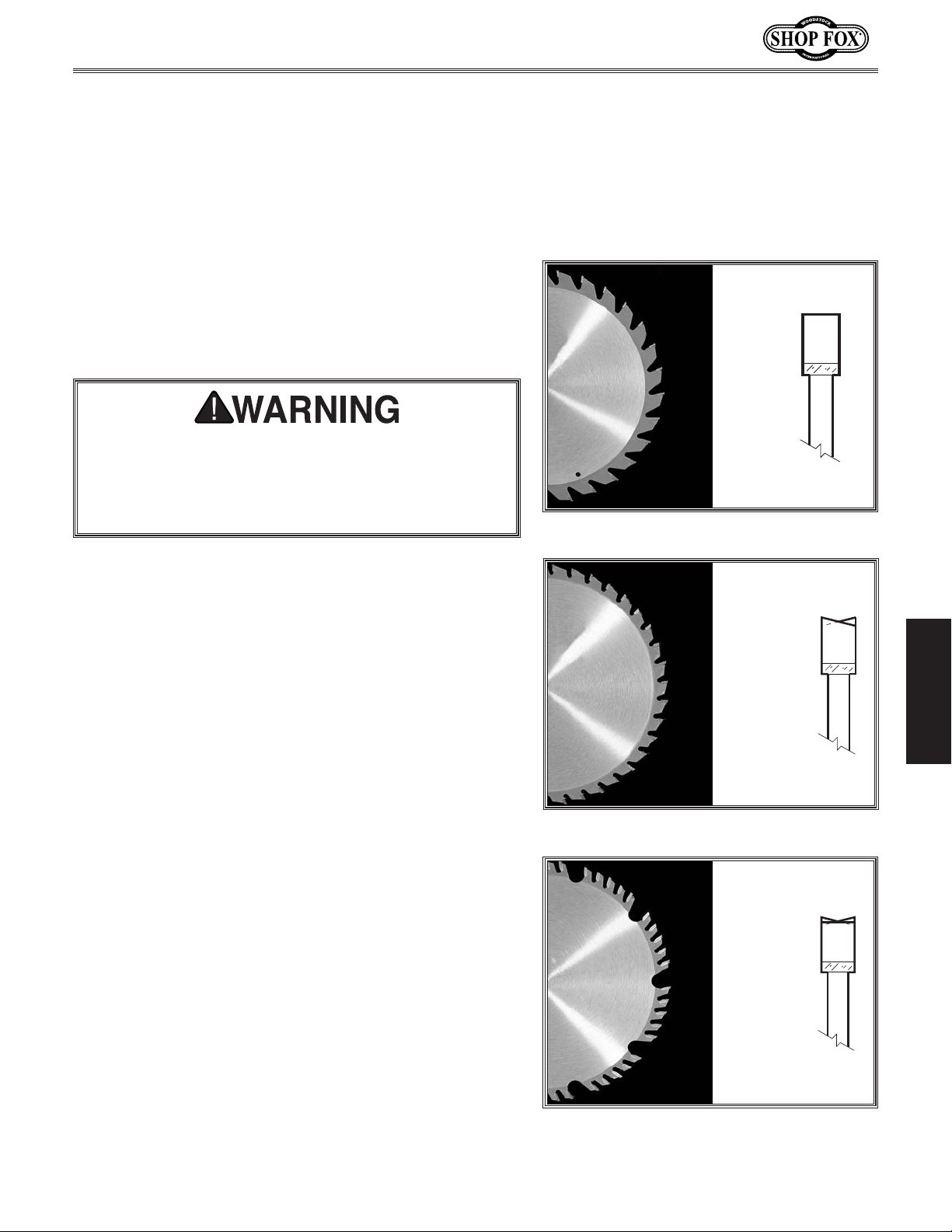
Figure 18. Example of a ripping blade.
Blade Selection
This section on blade selection is by no means
comprehensive. Always follow the saw blade
manufacturer's recommendations to ensure safe and
efficient operation of your table saw.
Ripping Blade Features (Figure 18):
• Best for cutting with the grain
• 20-40 teeth
• Flat-top ground tooth profile
• Large gullets for large chip removal
Crosscut Blade Features (Figure 19):
• Best for cutting across the grain
• 60-80 teeth
• Alternate top bevel tooth profile
• Small hook angle and a shallow gullet
Combination Blade Features (Figure 20):
• Designed to cut both with and across grain
• 40-50 teeth
• Alternate top bevel and flat, or alternate top bevel
and raker tooth profile
• Teeth are arranged in groups
• Gullets are small and shallow (similar to a cross-cut
blade), then large and deep (similar to a ripping
blade
OPERATIONS
Alternate
Top
Bevel
Figure 19. Example of a crosscut blade.
Alternate
Top
Bevel
and
Flat
Figure 20. Example of a combination
blade.
-25-
Page 30
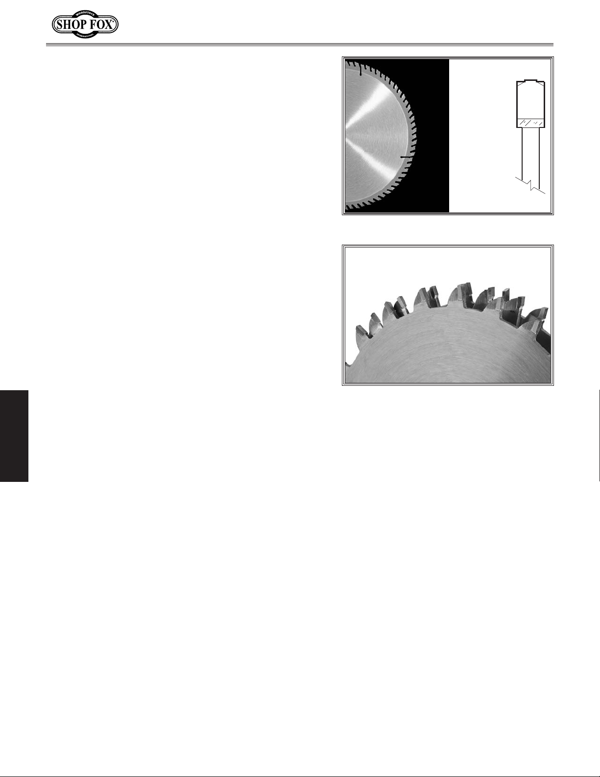
Laminate Blade Features (Figure 21):
• Best for cutting plywood or veneer
• 40-80 teeth
• Triple chip tooth profile
• Very shallow gullet
Thin Kerf Blade: A blade with thinner kerf than a
standard blade. Since the spreader/riving knife included
with this table saw is sized for standard blades, thin kerf
blades cannot be used on this saw unless they meet the
Blade Requirements specified in this manual; otherwise,
they will increase the risk of kickback.
Dado Blades
Stacked Dado Blade (see Figure 22): Multiple blades are
stacked together to control the cutting width. Stacked
dado blades are more expensive than wobble blades, but
typically produce higher quality results.
Model W1875 (For Machines Mfd. Since 1/20)
Triple
Chip
Blade
Figure 21. Example of a laminate blade.
Wobble Dado Blade: A single blade mounted at a slight
angle on an arbor hub. The blade angle is adjustable on
the hub, and the width of the dado cut is controlled by
the angle setting of the blade.
OPERATIONS
Figure 22. Stacked dado blade.
-26-
Page 31
Model W1875 (For Machines Mfd. Since 1/20)
Blade Installation
Review this section, even if your saw blade came preinstalled.
To remove & install blade, do these steps:
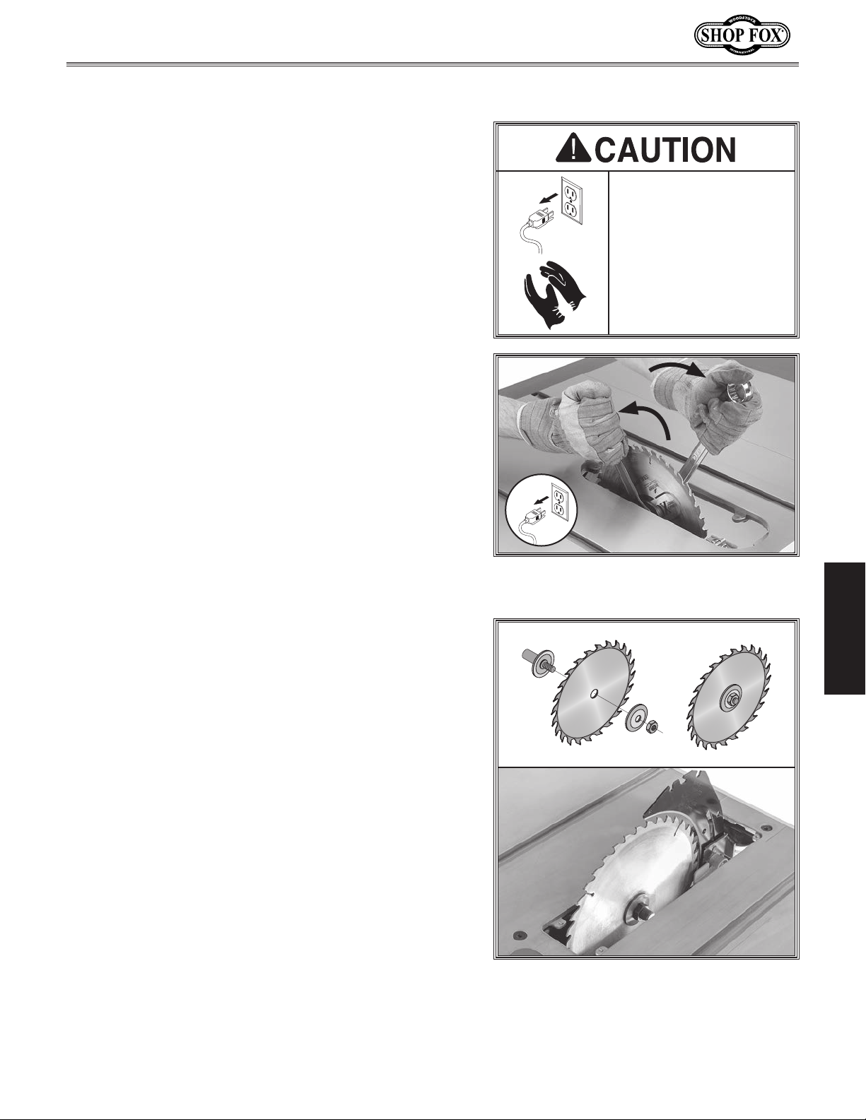
1. DISCONNECT MACHINE FROM POWER!
. Raise blade all the way up, then remove blade guard
2
and anti-kickback pawls (see
and spreader/riving knife.
. Use included arbor wrench on inner flange to hold
3
blade in place.
Use second included arbor wrench to loosen and
4.
remove arbor nut and flange (see
nut has right-hand threads; rotate counterclockwise
to loosen.
Page 28), table insert,
Figure 23). Arbor
To reduce risk of injury,
always disconnect
power to saw before
changing blades. Since
the blade is sharp, use
extra care and wear
gloves when installing
it.
Figure 23. Example of removing table saw
blade.
OPERATIONS
Install new blade, flange, and arbor nut as shown in
5.
Figure 24, with blade teeth facing front of the saw.
. Re-install spreader, table insert, and blade guard
6
with anti-kickback pawls (see
Page 28).
Figure 24. Correct order of installation
with teeth facing the correct direction.
-27-
Page 32
Blade Guard Assembly
Clear
Shield
Spreader
Pawls
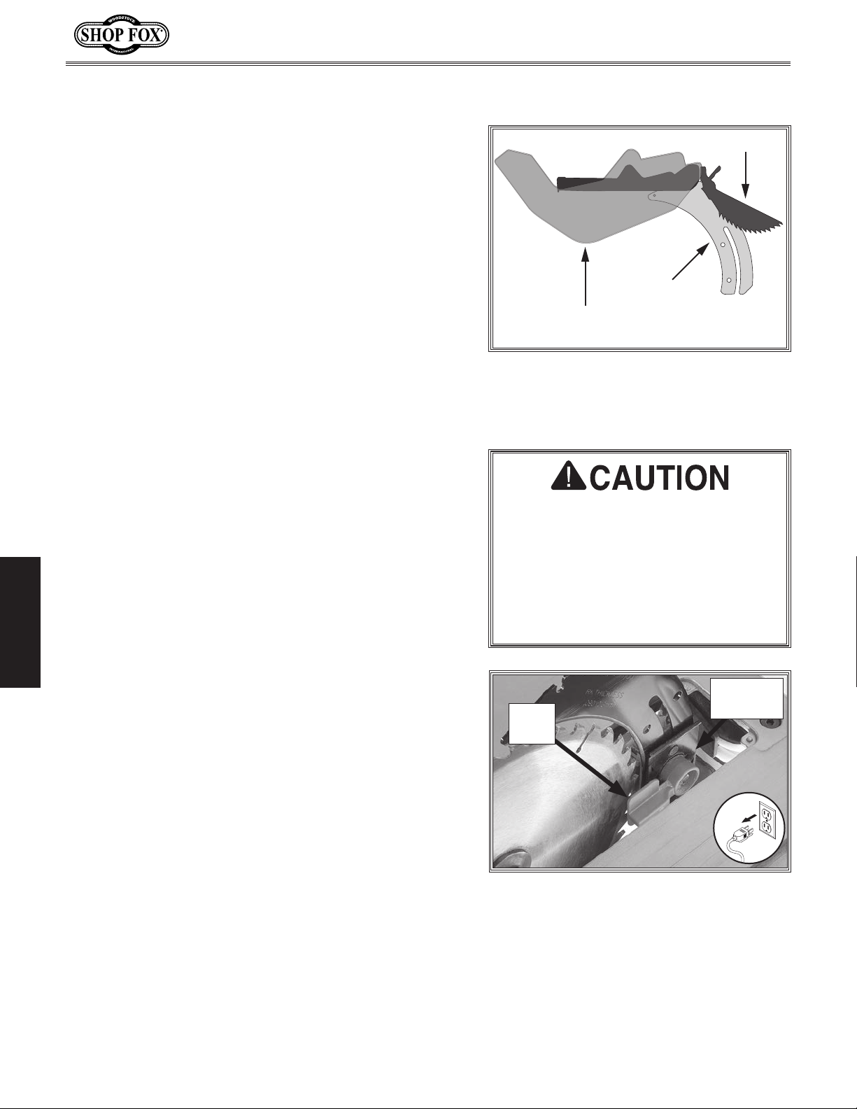
The term "blade guard" refers to the assembly that
consists of the clear polycarbonate shield, the spreader,
and the anti-kickback pawls on each side of the spreader
Figure 25). Each of these components has important
(see
safety functions during the operation of the saw.
Guard
The clear polycarbonate guard allows the operator to
see the blade cut the workpiece during operation. This
guard is designed to lift as the workpiece is pushed into
the blade and remain in contact with the workpiece
throughout the entire cut.
Model W1875 (For Machines Mfd. Since 1/20)
The guard reduces injury risk by providing a barrier
around the blade that prevents accidental contact and
contains flying wood chips.
To ensure that the guard does its job effectively, the
guard must always be in the downward position against
the table during idle operation, and the hinge mechanism
must be maintained in good working condition so the
guard can freely pivot up and down to accommodate the
height of the workpiece and return to the table surface.
Spreader/Riving Knife
The spreader/riving knife is a metal plate that prevents
the newly cut kerf of the workpiece from pinching the
backside of the blade, causing kickback.
OPERATIONS
The spreader/riving knife also acts as a barrier behind the
blade to shield hands from being pulled into the blade if a
kickback occurs.
Installing Blade Guard & Spreader/Riving Knife
DISCONNECT MACHINE FROM POWER!
1.
Figure 25. Blade guard assembly
components.
In order to work properly, the spreader
cannot be bent or misaligned with
the blade. If the spreader accidentally
gets bent, take the time to straighten
it or just replace it. Using a bent or
misaligned spreader will increase the
risk of kickback! Refer to Page 51 to
check or adjust alignment if necessary.
Spreader
Lock
Lever
Clamp
2. Raise blade all the way up, then remove table
insert.
Lift lock lever up to release spreader/riving knife
3.
clamp (see
Figure 26).
Figure 26. Spreader lock lever.
-28-
Page 33
Model W1875 (For Machines Mfd. Since 1/20)
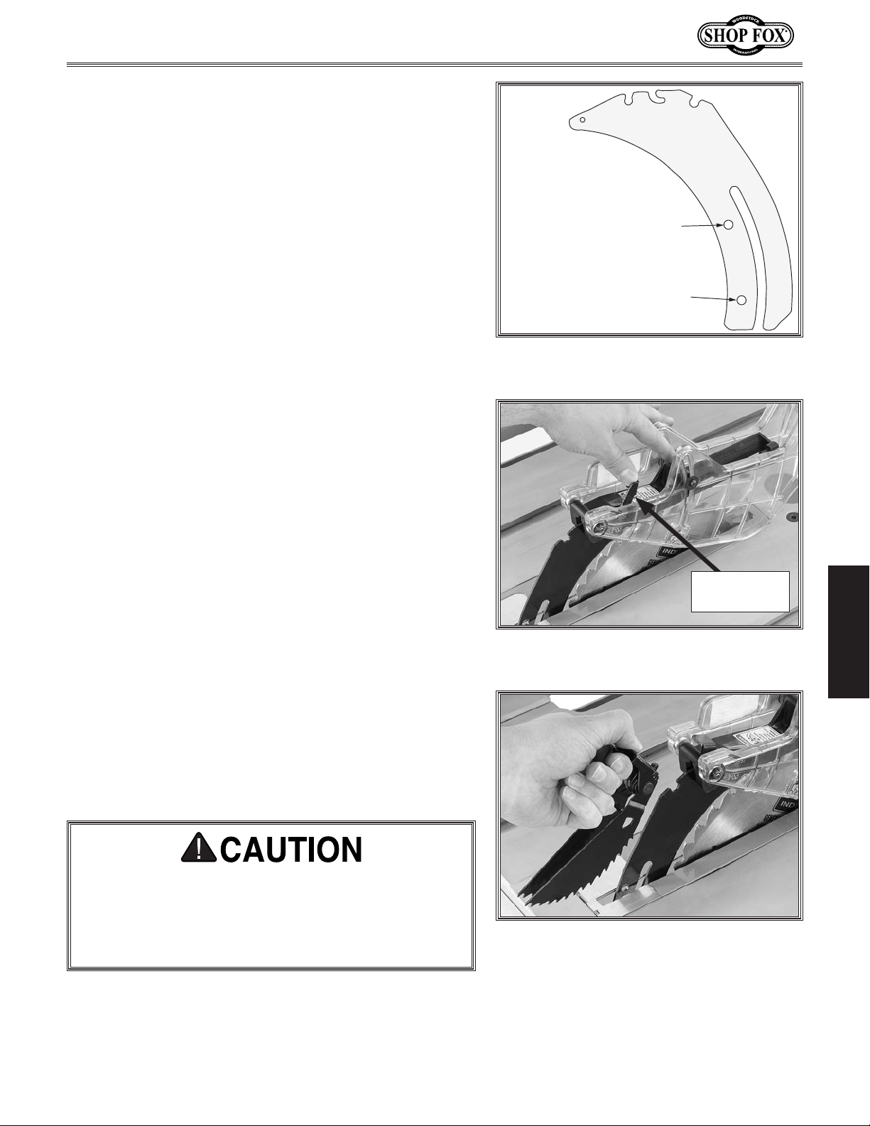
Top hole / down position
= riving knife position.
Bottom hole / up position
= blade guard position.
4. Push spreader/riving knife towards lock lever to
disengage positioning pins.
Pull spreader/riving knife upwards until positioning
5.
pins lock into lowest mounting holes (see
Push lock lever down and check spreader/riving
6.
knife alignment (see Page 51).
Install table insert.
7.
Insert rear shaft of blade guard into middle slot
8.
of spreader/riving knife as seen in
blade guard lock lever forward and pivot guard until
it is parallel with table.
Figure 28. Pull
Figure 27).
Figure 27. Spreader/riving knife mounting
positions.
Push down blade guard lock lever to secure position.
9.
Tug blade guard to make sure it is locked in place.
Hold pawls assembly lock lever and insert front of
10.
pawls assembly into rear slot of spreader/riving knife
as shown in
Release lever. Tug pawls assembly to make sure it is
11.
locked in place.
The blade guard assembly reduces the risk of
laceration and amputation injuries and MUST always
be installed on the saw for all normal through cuts.
For more information on the spreader/riving knife
and how to use it, refer to Page 31.
Figure 29.
Blade Guard
Lock Lever
Figure 28. Placing blade guard on
spreader/riving knife.
Figure 29. Installing pawls assembly.
OPERATIONS
-29-
Page 34
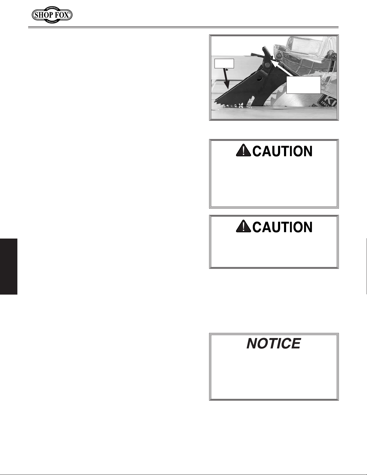
Anti-Kickback Pawls
The anti-kickback pawls allow the workpiece to travel in
only one direction. If the workpiece moves backwards,
such as during a kickback, the pawls will dig into the
workpiece to slow or stop it.
To work properly, the pawls must return to their resting
position after pivoting, as shown in
If the pawls fail to return to the resting position, the pivot
area may need to be cleaned or the spring may have been
dislodged or broken and will need to be fixed/replaced.
Disabling Pawls
You might disable the pawls if you are concerned
about them scratching a delicate workpiece, or if you
believe that they will obstruct a narrow workpiece and
cause feeding difficulty or loss of control. Use your
best judgment before retracting the pawls, as they are
provided for your safety.
To disable pawls, do these steps:
Figure 30.
Model W1875 (For Machines Mfd. Since 1/20)
Pawls
Pawl Lock
Lever
Figure 30. Pawls in resting position.
We do not recommend disabling
pawls during normal operations
unless absolutely necessary. In most
situations, disabling pawls will increase
your risk of serious personal injury in
event of a kickback.
. DISCONNECT MACHINE FROM POWER!
1
. Hold pawl lock lever (see Figure 30) and pull front
2
of pawl assembly from spreader/riving knife.
When to Use Blade Guard
The blade guard assembly MUST always be installed on
the saw for all normal through cuts (those where the
blade cuts all the way through the thickness of the
OPERATIONS
workpiece). If the blade guard is removed for specific
operations, always immediately replace it after those
operations are complete.
When Not to Use Blade Guard
The blade guard cannot be used on any non-through
cuts (those in which the blade does not cut all the way
through the thickness of the workpiece).
Sometimes the blade guard or its components can get in
the way when cutting very narrow workpieces or other
specialized cuts. Because the blade guard is provided to
decrease your risk of injury, it should not be used if it
gets in the way of making a safe cut. Use good judgment!
The pawls are sharp and can lacerate
fingers or hands. Use caution, and wear
leather gloves when handling the pawls
to reduce risk of injury.
Whenever blade guard cannot be
used, spreader/riving knife must be
adjusted to riving knife position. For
more information on the spreader/
riving knife and how to use it, refer to
Page 31.
-30-
Page 35
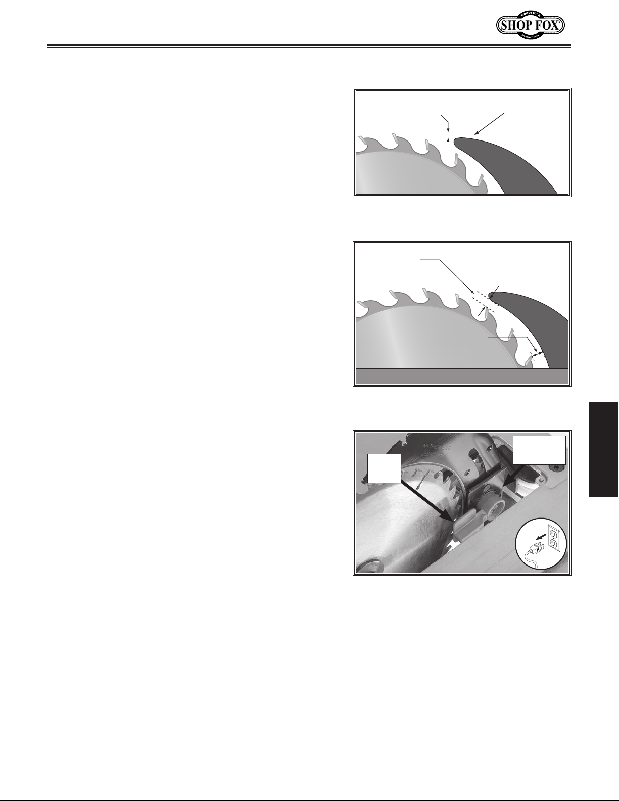
Model W1875 (For Machines Mfd. Since 1/20)
Riving Knife
The spreader also functions as a riving knife, which works
in the same manner as the spreader, but is used for nonthrough cuts. It is a metal plate that prevents the newly
cut workpiece from pinching the backside of the blade
and causing kickback.
The key difference between the spreader and the riving
knife is that the riving knife mounts below the blade's
highest point of rotation, as shown in
The height difference between the riving knife and the
blade allows the workpiece to pass over the blade during
non-through cuts (those in which the blade does not cut
all the way through the thickness of the workpiece).
The riving knife acts as a barrier behind the blade to
reduce the risk of hands being pulled into the blade if a
kickback occurs.
When used as a riving knife, the spreader/riving knife
must be kept within the range shown in
Therefore, we only recommend using a 10" blade for
operations that require use of the riving knife.
To adjust riving knife, do these steps:
Figure 31.
Figure 32.
Minimum 1mm
Maximum 5mm
Figure 31. Example of height difference
between riving knife and blade.
Top Distance
Minimum 3mm
Maximum 8mm
Bottom Distance
Minimum 3mm
Maximum 8mm
Figure 32. Example of allowable distance
between riving knife and blade.
Height Difference
Riving
Knife
Riving
Knife
Table
OPERATIONS
DISCONNECT MACHINE FROM POWER!
1.
2. Raise blade all the way up, then remove table
insert.
Lift lock lever up to release spreader/riving knife
3.
clamp (see
Push spreader/riving knife towards lock lever to
4.
disengage positioning pins.
Figure 33).
Lock
Lever
Figure 33. Spreader lock lever.
Spreader
Clamp
-31-
Page 36
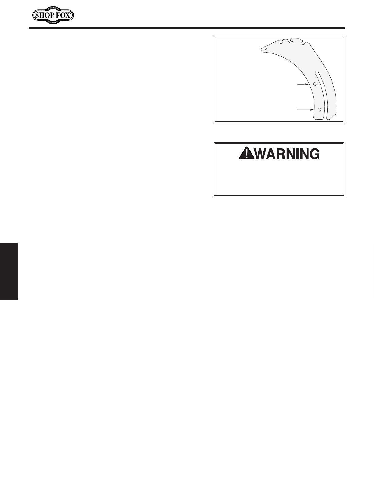
Top hole / down position
= riving knife position.
Bottom hole / up position
= blade guard position.
5. Push spreader/riving knife down until positioning
pins lock into top mounting holes (see
Push lock lever down and check spreader/riving
6.
knife alignment (see Page 51).
Install table insert.
7.
Figure 34).
When to Use Riving Knife
Use the riving knife for all non-through cuts made with a
standard table saw blade (i.e., dadoes or rabbet cuts, and
when using a tenoning jig).
Also, use the riving knife for those special operations
where the blade guard or its components get in the way
of safe operation, such as with very narrow cuts.
When Not to Use Riving Knife
DO NOT use the riving knife with a dado blade. Dado
blades are too wide to be used with the spreader clamp
engaged and doing so can lead to operator injury and
machine damage.
Model W1875 (For Machines Mfd. Since 1/20)
Figure 34. Riving knife mounting positions.
To ensure riving knife works safely, it
MUST be aligned with and correctly
adjusted to blade. Refer to Page 51 to
check or adjust riving knife alignment.
In addition, although it is possible to use the riving knife
for through cutting operations, the blade guard offers
far more injury protection and risk reduction than the
riving knife. Therefore, we strongly recommend you use
the blade guard assembly instead of the riving knife for
through cuts.
OPERATIONS
-32-
Page 37
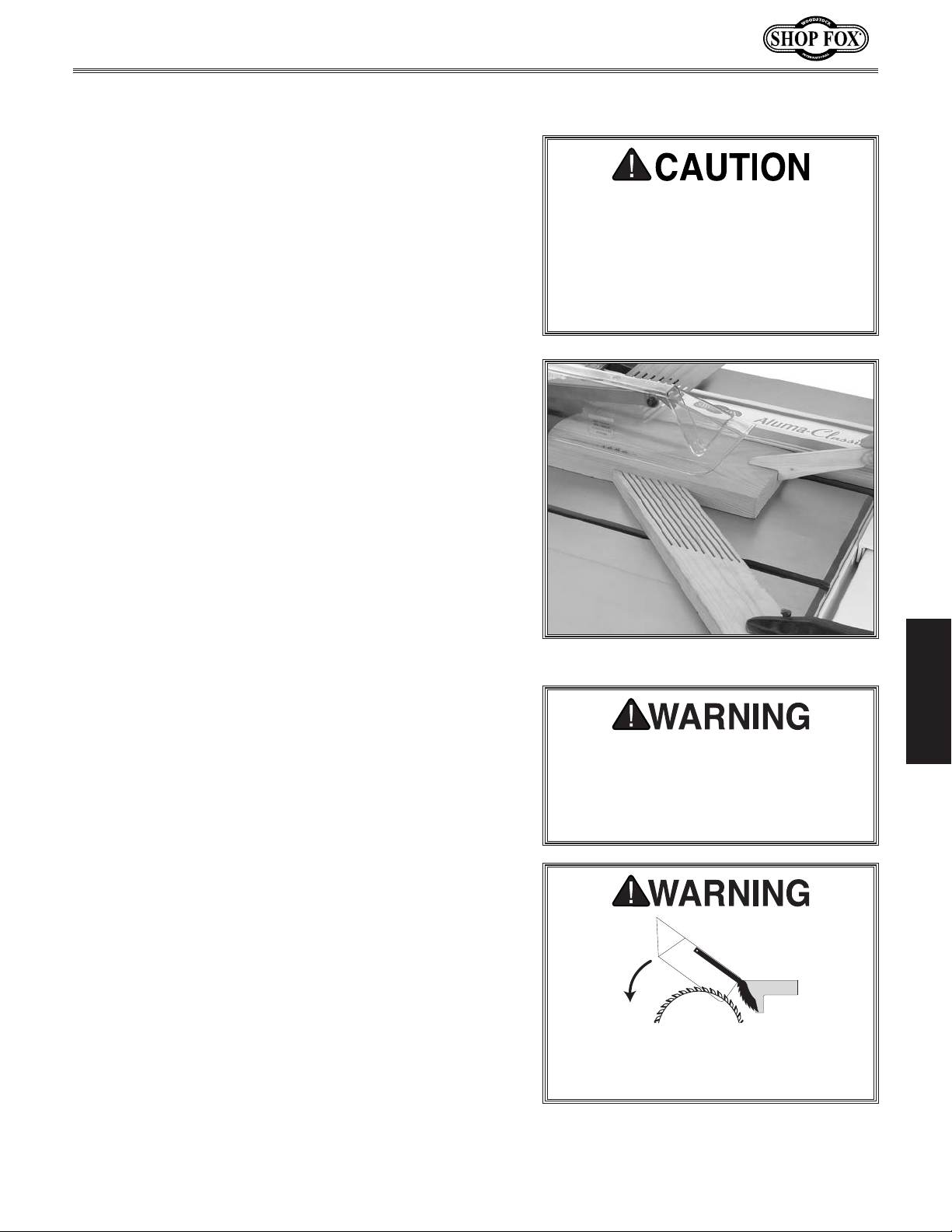
Model W1875 (For Machines Mfd. Since 1/20)
Ripping
Ripping means cutting with the grain of a natural wood
workpiece. In man-made materials such as MDF or
plywood, ripping simply means cutting lengthwise.
To make a rip cut, do these steps:
. Review Preventing Kickback on Page 12 and take
1
necessary precautions to reduce likelihood of
kickback.
. If using natural wood, joint one long edge of
2
workpiece on a jointer.
. DISCONNECT MACHINE FROM POWER!
3
Ensure that blade guard/spreader is installed.
4.
. Set fence to desired width of cut on scale.
5
Serious injury can be caused by
kickback. Kickback is a high-speed
ejection of stock from table saw
toward an operator. The operator or
bystanders may be struck by flying
stock, or the operator’s hands can be
pulled into blade during kickback.
6. Adjust blade height so highest saw tooth protrudes
no more than 1⁄4" above workpiece.
. Set up safety devices such as featherboards or other
7
anti-kickback devices, making sure no safety devices
are contacting blade.
. Plug saw into power source, turn it ON, and allow it
8
to reach full speed.
Note: Jointed edge of workpiece must slide against
fence during cutting operation.
Use a push stick to feed workpiece through saw blade,
9.
as shown in
beyond saw blade.
Figure 35, until workpiece is completely
OPERATIONS
Figure 35. Typical ripping operation.
Turn saw OFF and allow blade to come
to a complete stop before removing
cutoff piece. Failure to follow this
warning could result in severe cuts or
amputation.
-33-
Keep blade guard installed and in down
position. Failure to do this could result
in serious personal injury or death.
Page 38
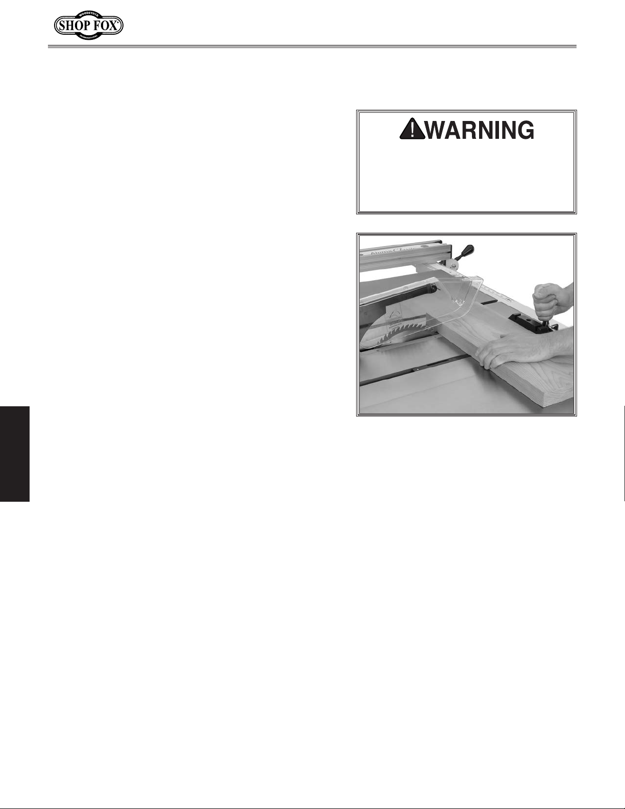
Crosscutting
"Crosscutting" means cutting across the grain of a natural
wood workpiece, usually with a miter saw. In other manmade materials, such as MDF or plywood, crosscutting
means cutting across the width of the workpiece.
To make a crosscut using miter gauge, do these steps:
DISCONNECT MACHINE FROM POWER!
1.
Ensure that blade guard assembly is installed.
2.
To avoid kickback, move rip fence aside and position
3.
miter gauge, adjusted to 90°, in a miter slot.
. Adjust blade height so teeth protrude no more than
4
1
⁄4" above workpiece.
. Slide miter gauge near blade and adjust workpiece
5
so blade will cut on waste side of line.
Model W1875 (For Machines Mfd. Since 1/20)
Turn saw OFF and allow blade to come
to a complete stop before removing
cutoff piece. Failure to follow this
warning could result in severe cuts or
amputation.
OPERATIONS
. Plug in table saw, turn it ON, and allow it to reach
6
full speed.
. Hold workpiece firmly against face of miter gauge
7
(as shown in Figure 36), and ease it through blade
until workpiece is completely past saw blade.
Figure 36. Typical crosscutting operation.
-34-
Page 39
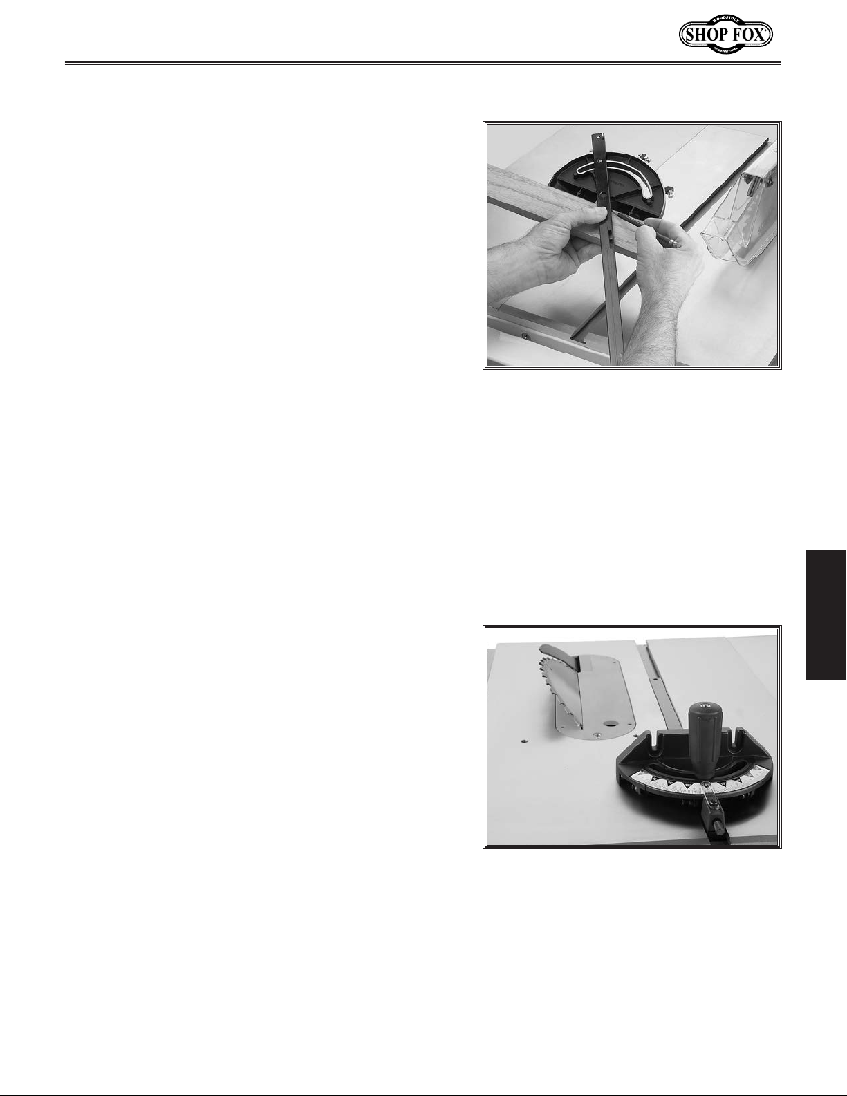
Model W1875 (For Machines Mfd. Since 1/20)
Miter Cuts
A miter cut is an angled crosscut. Miters are usually cut in
the same manner as crosscuts, using the miter gauge and
a predetermined mark on the workpiece.
To perform a miter cut, do these steps:
DISCONNECT MACHINE FROM POWER!
1.
Ensure that blade guard assembly is installed.
2.
Determine angle of cut. If angle needs to be precise,
3.
use a protractor to set miter gauge to blade.
Place face of miter gauge against edge of workpiece
4.
and place bar across face of workpiece. Use bar as a
guide to mark your cut, as shown in
Place miter gauge back into slot and hold workpiece
5.
firmly against miter gauge body. Slide miter gauge
near blade and adjust workpiece so blade will cut on
waste side of line.
Figure 37.
Figure 37. Example of marking miter line.
Proceed to make cut in same manner as described in
6.
Crosscutting instructions.
Blade Tilt/Bevel Cuts
The blade tilt handwheel allows the operator to tilt the
blade to the right, between 0° and 45°. This is used most
often when cutting bevels, compound miters, or chamfers.
Figure 38 shows an example of the blade when tilted to
4 5°.
OPERATIONS
Figure 38. Example of blade tilted to
45° for bevel cutting (blade guard only
removed for clarity).
-35-
Page 40
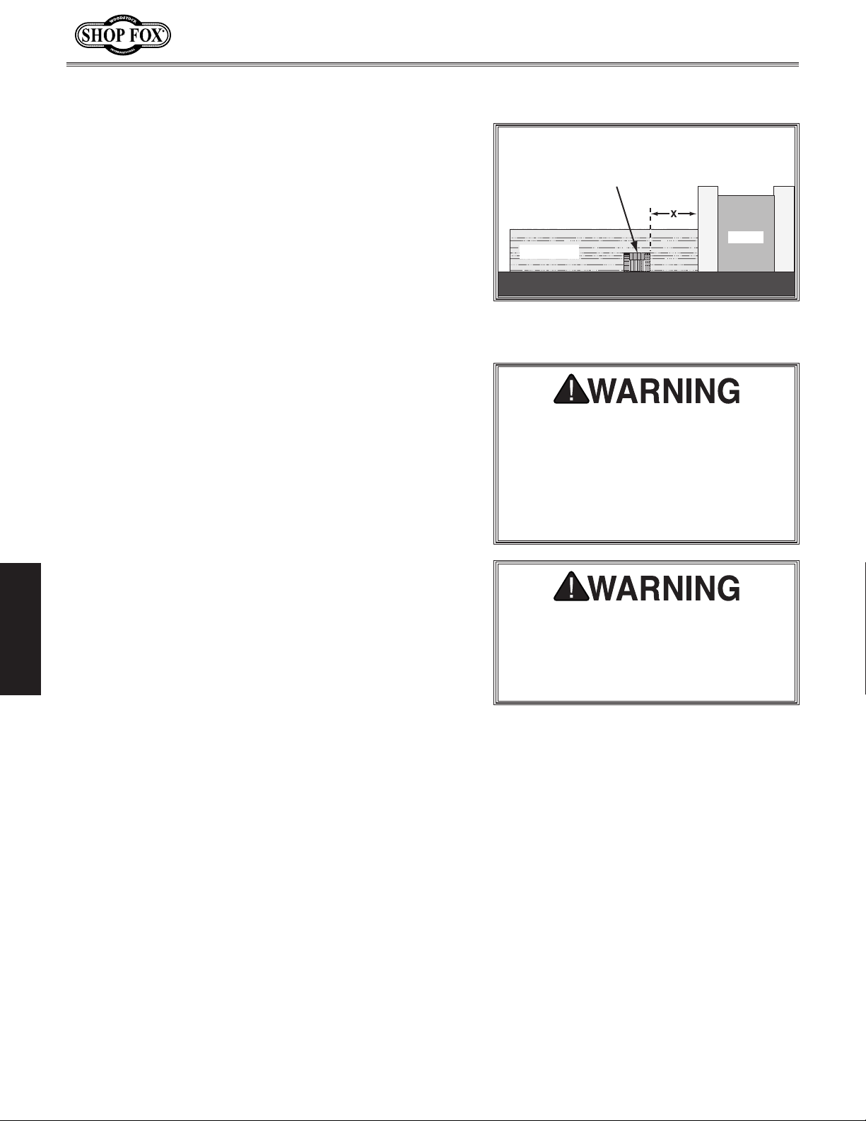
Dado Cutting
Commonly used in furniture joinery, a dado is a straight
channel cut in the face of the workpiece. Dadoes are
"non-through" cuts that can be made with a dado blade or
a standard saw blade. Figure
a dado cut being made with a dado blade.
39 shows a cutaway view of
Model W1875 (For Machines Mfd. Since 1/20)
Dado Blade
The Model W1875 can accommodate dado blades up to 10"
in diameter with a maximum thickness of
DO NOT use the riving knife if you install a dado blade.
13
/16".
Installing Dado Blade
1. DISCONNECT MACHINE FROM POWER!
. Remove table insert, blade guard assembly,
2
spreader/riving knife, and saw blade.
. Attach and adjust dado blade system according to
3
dado blade manufacturer’s instructions.
. Install included dado table insert.
4
OPERATIONS
Workpiece
Fence
Figure 39. Example of a dado being cut
with a dado blade.
DO NOT make through cuts with a dado
blade. The extra width of a dado blade
will increase risk of kickback during
a through cut. Dado blades are only
intended for non-through cuts. Failure
to heed this warning could result in
serious injury.
Never try to cut a warped board by
pushing it flat against the table. If
kickback occurs, your hand could be
pulled into blade, resulting in severe
cuts or amputation.
-36-
Page 41
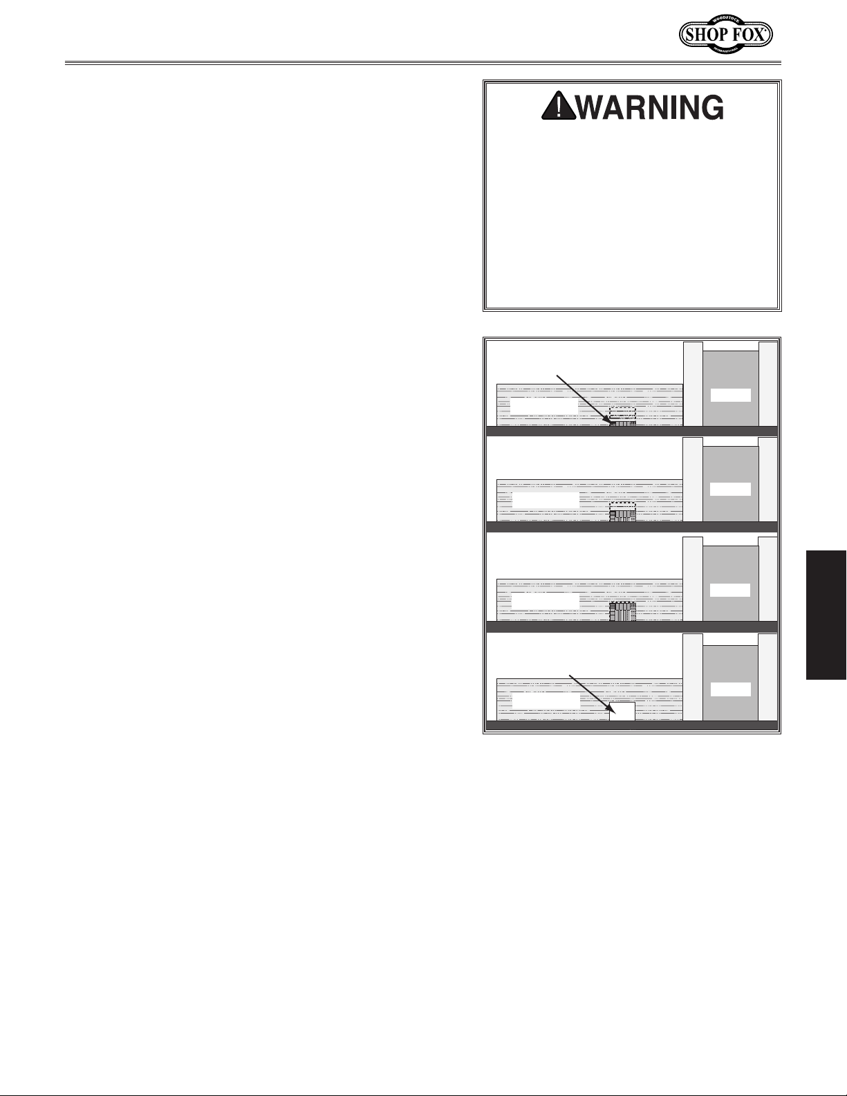
Model W1875 (For Machines Mfd. Since 1/20)
Cutting Dadoes with a Dado Blade
Because dado blades are much wider than standard
blades, they place a greater amount of force against the
workpiece when cutting. This additional force increases
the risk of kickback, requiring the operator to take
additional steps when cutting to keep the risk of injury at
an acceptable level.
Figure 40 demonstrates the sequential process of making
multiple, light cuts that get progressively deeper. The
actual number of cuts used should be determined by
workpiece hardness, total dado depth, and feed rate. In
general, if you hear the motor slow down during the cut,
you are cutting too deep or feeding too fast. Slow down!
Dado blades have a higher risk of
kickback than normal blades because
their larger size applies stronger forces
to the workpiece. This risk increases
relative to depth and width of cut. To
minimize your risk of serious personal
injury, ensure that stock is flat and
straight, and make multiple light cuts
(rather than one deep cut) to achieve
desired cutting depth.
To cut dado with dado blade, do these steps:
. DISCONNECT MACHINE FROM POWER!
1
Adjust dado blade to desired depth of cut.
2.
Adjust distance between fence and inside edge of
3.
blade, as shown in Figure 39 on Page 36, to dado
length of a workpiece.
— If dadoing across workpiece, use miter gauge and
carefully line up desired cut with dado blade. DO
NOT use fence in combination with miter gauge.
Reconnect saw to power source.
4.
5. Turn saw ON. Blade should run smoothly, with no
vibrations.
When blade has reached full speed, perform test cut
6.
with scrap piece of wood.
— If cut is satisfactory, repeat cut with actual
workpiece.
Dado Blade
Workpiece
Cut 1
Fence
Cut 2
Workpiece
Fence
Cut 3
Workpiece
Finished
Dado Cut
Workpiece
Figure 40. Example of dado being cut with
multiple light cuts, instead of one deep
cut.
Fence
Fence
OPERATIONS
-37-
Page 42
Cutting Dadoes with a Standard Blade
A ripping blade (described on
best blade to use when cutting dadoes with a standard
blade because it removes sawdust very efficiently.
To use standard saw blade to cut dadoes, do these
steps:
DISCONNECT MACHINE FROM POWER!
1.
. Mark width of dado cut on workpiece. Include marks
2
on edge of workpiece so cut path can be aligned
when workpiece is lying on table.
Raise blade up to desired depth of cut (depth of
3.
dado channel desired).
Set saw up for type of cut you need to make,
4.
depending on whether it is a rip cut (Page 33) or
crosscut (Page
Align blade to cut one side of dado, as shown in
5.
Figure 41.
34).
Page 25) is typically the
Model W1875 (For Machines Mfd. Since 1/20)
Cut 1
Workpiece
Figure 41. First cut for a single-blade
Cut 2
Workpiece
Figure 42. Second cut for a single-blade
Blade
Fence
dado.
Blade
Fence
dado.
OPERATIONS
. Reconnect saw to power source and turn saw ON.
6
Allow blade to reach full speed, then perform
cutting operation.
. Repeat cutting operation on other side of dado, as
7
shown in Figure 42.
. Make additional cuts (see Figure 43) in center
8
of dado to clear out necessary material. Dado is
complete when channel is completely cleared out.
Cuts 3+
Fence
Workpiece
Figure 43. Additional single-blade dado
cuts.
-38-
Page 43
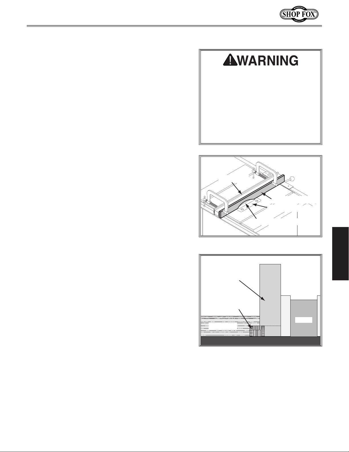
Model W1875 (For Machines Mfd. Since 1/20)
Rabbet Cutting
Commonly used in furniture joinery, a rabbet cut is
an L-shaped groove cut in the edge of the workpiece.
Rabbets can be cut with either a dado blade or a standard
saw blade.
Rabbet cutting along the edge of a workpiece with a dado
blade requires a sacrificial fence (see
the sacrificial fence the same length as the fence and
3
⁄4" thick. Attach it to the fence with screws or clamps,
making sure they are all secure and tight. Raise the blade
into the sacrificial fence to the height and rabbet width
needed.
When using a dado blade, the included dado table insert
must be installed and used during rabbeting operations.
Figure 44). Make
Dado blades have a higher risk of
kickback than normal blades because
their larger size applies stronger forces
to the workpiece. This risk increases
relative to the depth and width of the
cut. To minimize your risk of serious
personal injury, ensure that stock is
flat and straight, and make multiple
light cuts (rather than one deep cut) to
achieve the desired cutting depth.
Cutting Rabbets with a Dado Blade
1. DISCONNECT MACHINE FROM POWER!
. Lower dado blade all the way down.
2
3. Secure sacrificial fence with clamps to fence.
Note: Be sure to allow adequate clearance below
clamps for workpiece to travel freely.
Position fence so dado blade protrudes beyond fence
4.
the same amount as desired width of rabbet (see
Figure 45).
Mark a reference line on the face of the sacrificial
5.
fence indicating approximate rabbet depth.
Secure fence, reconnect machine to power, and turn
6.
machine ON.
Slowly raise dado blade into sacrificial fence until it
7.
reaches line marked previously on sacrificial fence.
Rip Fence
Sacrificial Fence
Dado Insert
Blade Cut-Out
OPERATIONS
Figure 44. Example of sacrificial fence.
Sacrificial Fence
Dado Blade
Fence
Workpiece
Perform test cut on a scrap piece of wood to verify
8.
rabbet height and width.
If cut is satisfactory, repeat cut with workpiece.
—
-39-
Figure 45. Rabbet cutting.
Page 44
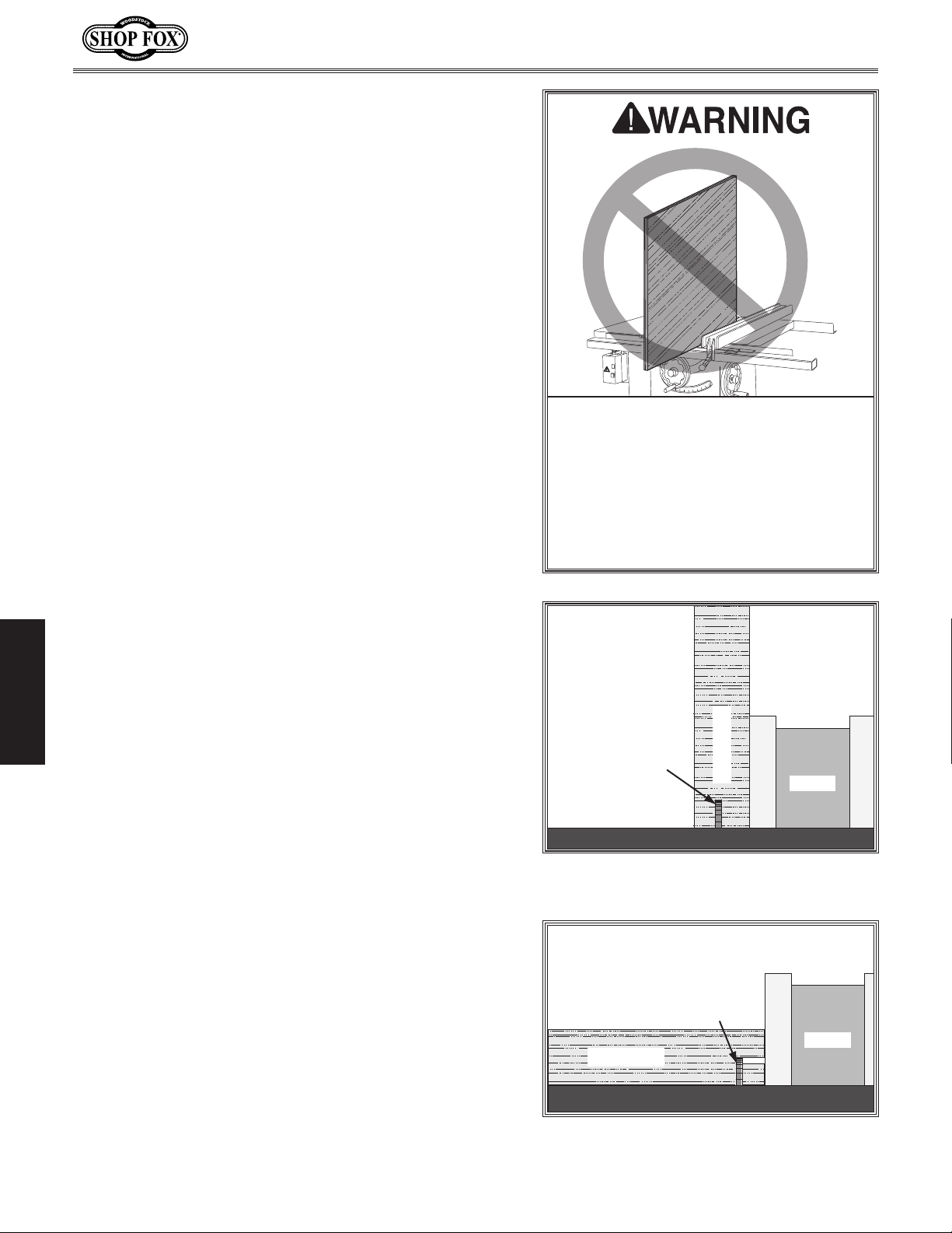
Cutting Rabbets with a Standard Blade
A ripping blade is typically the best blade to use for
cutting rabbets when using a standard blade because it
removes sawdust very efficiently. (See
details.) Also, a sacrificial fence is not required when
cutting rabbets with a standard blade.
To cut rabbets with standard blade, do these steps:
DISCONNECT MACHINE FROM POWER!
1.
Ensure that riving knife and standard table insert are
2.
installed.
. Mark width of rabbet cut on edge of workpiece,
3
so you can clearly identify intended cut while it is
laying flat on saw table.
. Raise blade up to desired depth of cut (depth of
4
rabbet channel desired).
Page 25 for blade
Model W1875 (For Machines Mfd. Since 1/20)
45
30
15
DO NOT place a tall board on edge to
perform a rabbet cut with a standard
blade. Workpieces that are too tall
to properly support with fence can
easily shift during operation and cause
kickback. Instead, place stock flat on
saw and perform rabbet cut with a
dado blade, as instructed on Page 39.
5. Stand workpiece on edge, as shown in Figure 46,
then adjust fence so blade is aligned with inside of
your rabbet channel.
— If workpiece is very tall, or is unstable when
placed against fence, lay it flat on table and use a
OPERATIONS
6
7
dado blade to perform rabbet cut.
. Reconnect saw to power source, then perform cut.
. Lay workpiece flat on table, as shown in Figure 47,
adjust saw blade height to intersect with first cut,
then perform second cut to complete rabbet.
Blade
Workpiece
Fence
Figure 46. Example of rabbet cutting with
a standard blade.
Blade
Fence
Workpiece
-40-
Figure 47. Example of second cut to cre-
ate a rabbet.
Page 45
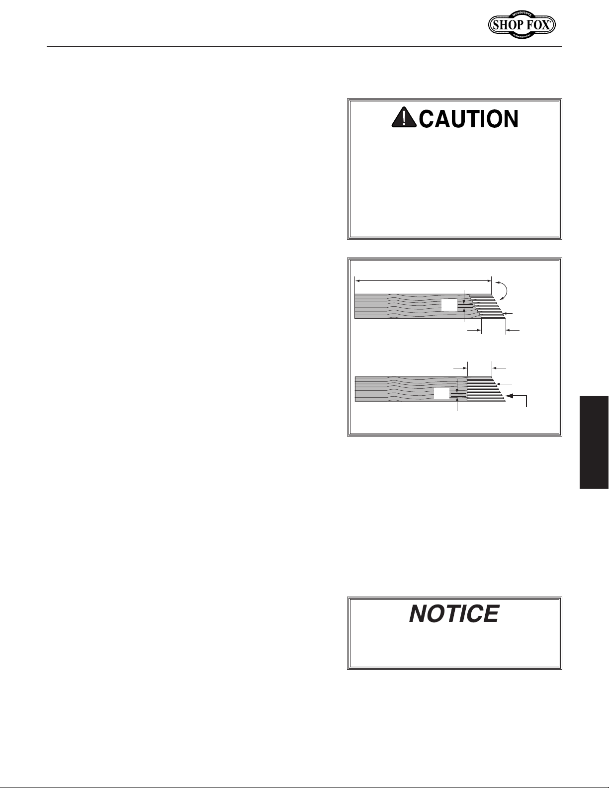
Model W1875 (For Machines Mfd. Since 1/20)
SHOP-MADE SAFETY ACCESSORIES
Featherboards
Easily made from scrap stock, featherboards provide an
added degree of protection against kickback, especially
when used together with push sticks. They also maintain
pressure on the workpiece to keep it against the fence
or table while cutting, which makes the operation easier
and safer because the cut can be completed without the
operator’s hands getting near the blade. The angled ends
and flexibility of the fingers allow the workpiece to move
in only one direction.
Making a Featherboard
This sub-section covers the two basic types of
featherboards: 1) Those secured by clamps, and 2) those
secured with the miter slot.
Material
Hardwood 3⁄4" x 3" x 10" (Minimum) .........................1
Hardwood
Additional Material Needed for Mounting Featherboard:
Hardwood 3⁄8" x (Miter Slot Width) x 5"L ...................1
Wing Nut
Flat Head Screw
Flat Washer
To make a featherboard, do these steps:
Needed for Featherboard:
3
⁄4" x 6" x 28" (Maximum) .........................1
1
⁄4"-20 .................................................1
1
⁄4"-20 x 2" ..................................1
1
⁄4"-20 .............................................1
We recommend using a bandsaw
for making fingers in the next step
because it tends to be safer. A table
saw can be used, but it will over-cut
the underside of the ends, produce a
thicker kerf, and require you to stop
the blade half-way through the cut,
which can be dangerous.
10" (Minimum)
30°
3
/8"
A
Initial Cut
2"—3"
3
/8"
B
Kerf
1
/16"—1/8"
2"—3"
Kerf
1
/16"—1/8"
Progressively
Longer Cuts
Figure 48. Patterns for making
featherboards.
OPERATIONS
1. Cut a hardwood board that is approximately 3⁄4"
thick to size. The length and width of the board can
vary according to your design. Most featherboards
are 10"–28" long and 3"–6" wide. Make sure wood
grain runs parallel with length of featherboard, so
fingers you will create in
Step 3 will bend without
breaking.
Cut 30º angle at one end of board.
2.
Make a series of end cuts with the grain 3⁄8"– 1⁄4"
3.
apart and 2"–3" long, as shown in
Figure 48
(A). Alternatively, start cuts at 2"–3" deep, then
make them progressively deeper, as shown in
Figure 48 (B).
-41-
IM P O R TA N T: Cuts made across grain result
in weak fingers that easily break when
flexed. When made correctly, fingers
should withstand flexing from moderate
pressure. To test finger flexibility, push
firmly on ends with your thumb. If fingers
do not flex, they are likely too thick (cuts
are too far apart).
Only Steps 1–3 are required to make a
clamp-mounted featherboard. Refer to
Page 43 for instructions on clamping.
Page 46

4. Rout a 1⁄4"–3⁄8" wide slot 4"–5" long in workpiece and
1"–2" from short end of featherboard (see
Figure
49).
Cut a miter bar approximately 5" long that will fit in
5.
table miter slot, as shown in
Figure 50.
Model W1875 (For Machines Mfd. Since 1/20)
1
/4"—3/8" Slot
1"—2"
Tip: Consider making miter bar longer for larger
featherboards—approximately half the length of
total featherboard—to support force applied to the
featherboard during use.
Drill a 1⁄4" hole in center of bar, then countersink
6.
bottom to fit a
Mark a 4" line through center of countersunk hole in
7.
1
⁄4"-20 flat head screw.
center, then use a jig saw with a narrow blade to cut
it out.
Assemble miter bar and featherboard with a 1⁄4"-
8.
20 flat head screw, flat washer, and a wing nut or
a star knob (see
Figure 51). Congratulations! Your
featherboard is complete.
Note: The routed slot, countersunk hole, and flat
head screw are essential for miter bar to clamp into
miter slot. When wing nut is tightened, it will draw
flat head screw upward into countersunk hole. This
will spread sides of miter bar and force them into
walls of miter slot, locking featherboard in place.
Tip: The length of the flat head screw depends on
OPERATIONS
the thickness of the featherboard—
though 1 1⁄2" to 2"
lengths usually work.
9. Now, proceed to Mounting Featherboard in Miter
Slot on Page 43.
4"—5"
Figure 49. Slot routed in featherboard.
(Top View)
5"
3
/8"
1
/4" Hole
Countersink on Bottom
4" Slot
(Side View)
5"
Figure 50. Miter bar pattern.
Wing Nut
(Side View)
Flat Washer
Featherboard
Miter Bar
Flat Head Screw
Figure 51. Assembling miter slot
featherboard components.
-42-
Page 47
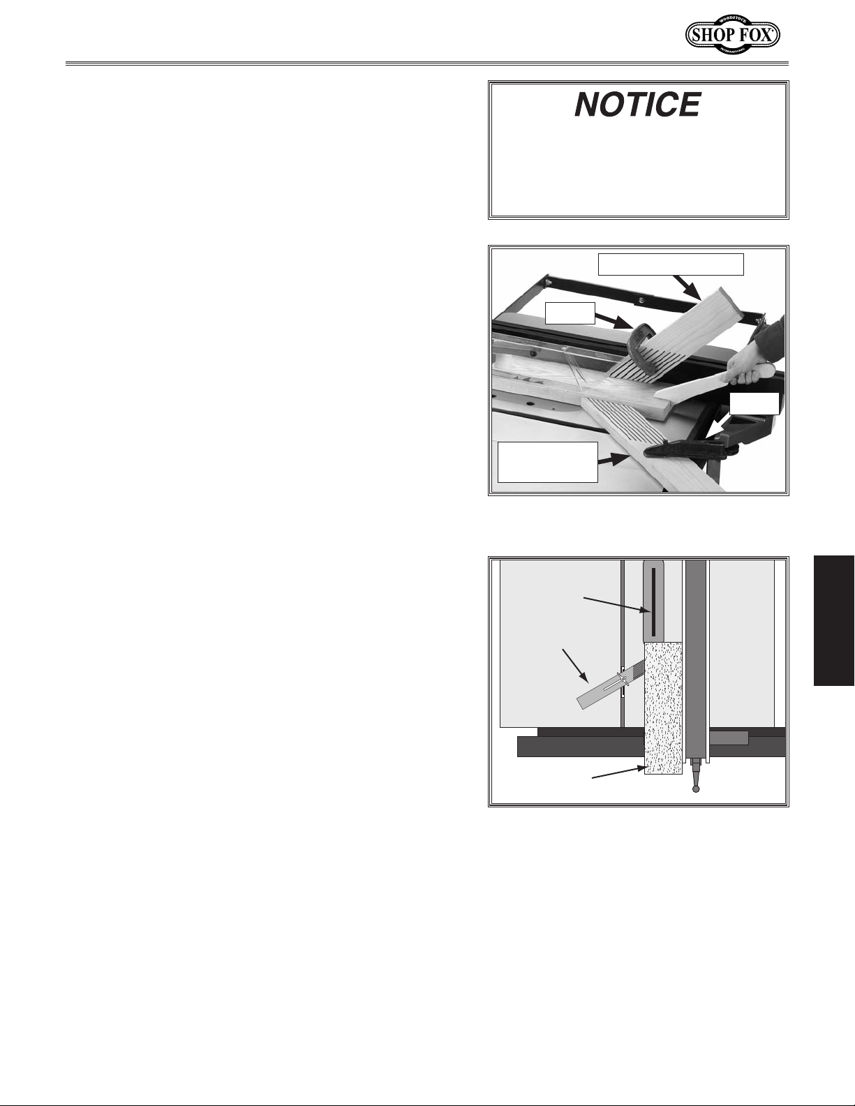
Model W1875 (For Machines Mfd. Since 1/20)
Mounting Featherboard w/Clamps
1. Lower saw blade, then adjust fence to desired width
and secure it.
. Place workpiece against fence, making sure it is 1" in
2
front of the blade.
. Place a featherboard on table away from blade so
3
all fingers point forward and contact workpiece (see
Figure 52).
. Secure featherboard to table with a clamp.
4
5. Check featherboard by pushing it with your thumb to
ensure it is secure.
— If featherboard moves, tighten clamp more.
6. Optional: If cutting long workpieces, it may be
beneficial to use another featherboard to keep board
firmly against table while feeding.
The featherboard should be placed
firmly enough against the workpiece
to keep it against the fence but not
so tight that it is difficult to feed the
workpiece.
Fence Featherboard
Clamp
Clamp
Table
Featherboard
Mounting Featherboard in Miter Slot
1. Lower saw blade, then adjust fence to desired width
and secure it.
. Place workpiece evenly against fence, making sure it
2
is 1" in front of blade.
. Slide featherboard miter bar into miter slot, making
3
sure fingers slant toward blade, as shown in Figure
53.
. Position fingered edge of featherboard against edge
4
of workpiece, so that all fingers contact workpiece.
Slide featherboard toward blade until first finger is
nearly even with end of workpiece, which should be
1" away from blade.
. Double check workpiece and featherboard to
5
ensure they are properly positioned, as described in
Step 4. Then secure featherboard to table. Check
featherboard by hand to make sure it is tight.
Note: The featherboard should be placed firmly
enough against workpiece to keep it against
fence but not so tight that it is difficult to feed
workpiece.
Figure 52. Example of featherboards
secured with clamps.
OPERATIONS
Blade
Featherboard
Workpiece
Figure 53. Featherboard installed in miter
slot and supporting workpiece for ripping
cut.
-43-
Page 48
Push Sticks
When used correctly, push sticks reduce the risk
of injury by keeping hands away from the blade
while cutting. In the event of an accident, a
push stick can also absorb damage that would
have otherwise happened to hands or fingers.
Model W1875 (For Machines Mfd. Since 1/20)
Supporting: A second push stick can be used
to keep the workpiece firmly against the fence
while cutting. When using a push stick in this
manner, only apply pressure before the blade;
otherwise, pushing the workpiece against
or behind the blade will increase the risk of
kickback (see
Push Stick Prohibition Zone in
Figure 54 below).
Using a Push Stick
Use push sticks whenever your hands will get
within 12" of the blade. To maintain control
when cutting large workpieces, start the cut by
feeding with your hands then use push sticks to
finish the cut, so your hands are not on the end
of the workpiece as it passes through the blade.
Feeding: Place the notched end of the push
stick against the end of the workpiece (see
Figure
55 below), and move the workpiece into
the blade with steady downward and forward
pressure.
Making a Push Stick
Use this template to make
your own push stick.
90º
OPERATIONS
Figure 54. Using push sticks to rip narrow stock.
15
3
/
Figure 55. Side view of a push stick in-use.
4
" Minimum Length
Push Stick
Supporting
Push Stick
Prohibition
Zone
Blade
Path
Feeding
Store Push
Stick Here
for Easy
Access
Push Stick
Cut here to
1
⁄4" stock
push
Cut here to push 1⁄2" stock
Notch for placing on
corners of workpieces
MATERIAL: Only use hardwood, sturdy plywood, or
high-density plastic. Do not
use softwood that may break
under pressure or metal that
1
⁄2" Grid
can break teeth from the
blade!
Notch to help
prevent hand
from slipping
SANDING: Sand
edges to remove
rough edges and
increase comfort.
SIZING: Push stick must
be at least 15
1
⁄2"—3⁄4" thick
Use
material.
3
⁄4" long.
Figure 56. Template for a basic shop-made push stick (not shown at actual size).
-44-
Page 49
Model W1875 (For Machines Mfd. Since 1/20)
Push Blocks
When used correctly, a push block reduces
the risk of injury by keeping hands away from
the blade while cutting. In the event of an
accident, a push block often takes the damage
that would have otherwise happened to hands
or fingers.
The notched end of the push block is then
used to push the workpiece the rest of the way
through the cut, keeping the operator's hands at
a safe distance from the blade. A push stick is
often used at the same time in the other hand
to support the workpiece during the cut (see
Using a Push Stick on previous page).
Using a Push Block
A push block can be used in place of or in
addition to a push stick for feeding workpieces
into the blade. Due to their design, push blocks
allow the operator to apply firm downward
pressure on the workpiece that could not
otherwise be achieved with a push stick.
The push block design on this page can be used
in two different ways (see inset Figure
57
below). Typically, the bottom of the push block
is used until the end of the workpiece reaches
the blade.
Making a Push Block
Use this template to make your own push block.
Push Stick
Prohibition
Zone
Push Stick
Supporting
Blade
Path
Feeding
Push
Block
Figure 58. Using a push block and push stick to
make a rip cut.
CAUTION: Bottom
of handle must be
at least 4" above
bottom of push
block to keep
hand away from
blade.
OPERATIONS
Figure 57. Side view of a push block in use.
Notch for use
as a push stick
CAUTION: Only use hardwood, sturdy plywood, or
high-density plastic. Do not use softwood that
may break under pressure or metal that can break
teeth from the blade!
1
⁄2" Grid
Figure 59. Template for a shop-made push block (shown at 50% of full size).
Handle for
firm grip
Make push block with
1
⁄2"—3⁄4" thick material
Lip for pushing workpiece
9"−10" Minimum Length
-45-
1
⁄4"—1⁄2"
4"
Page 50
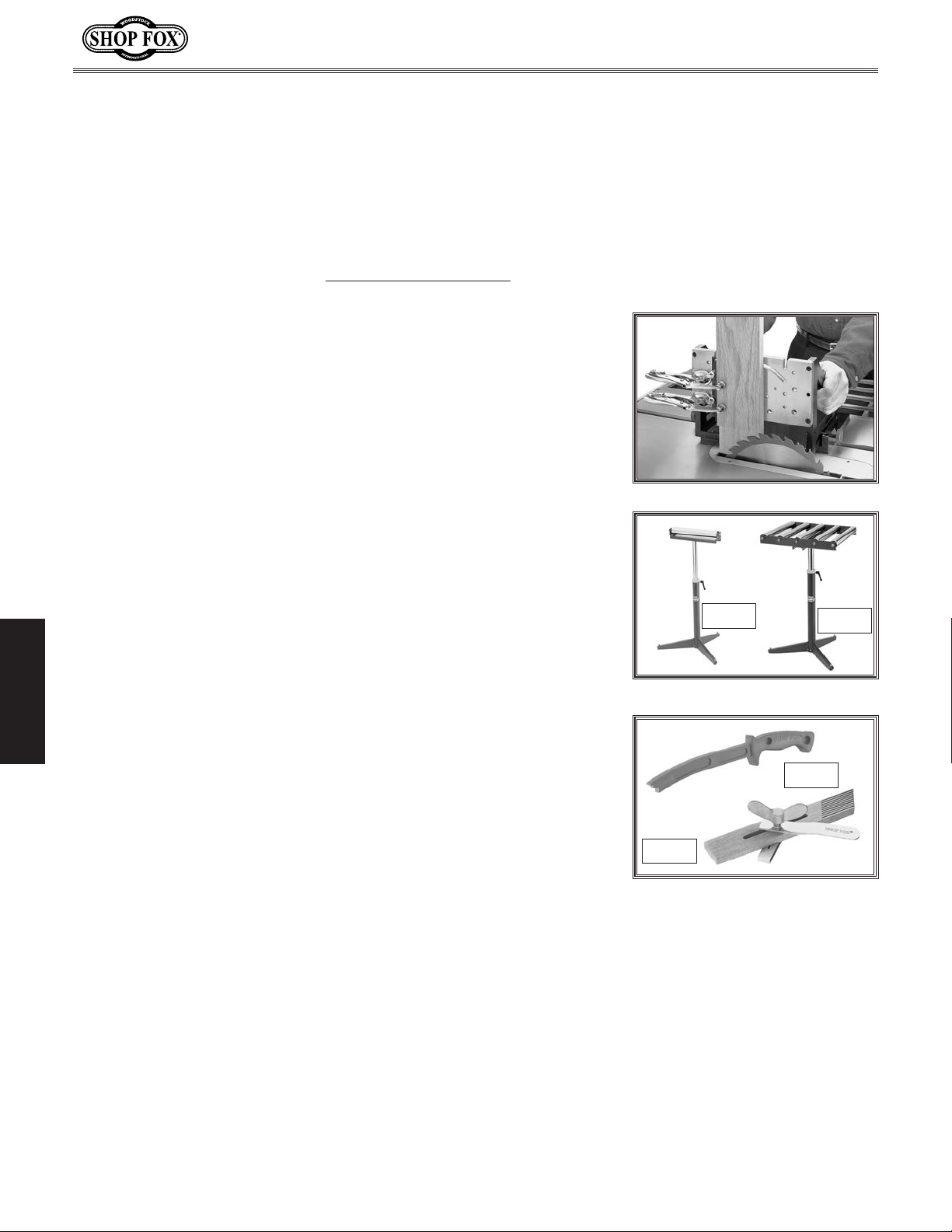
Model W1875 (For Machines Mfd. Since 1/20)
ACCESSORIES
Table Saw Accessories
The following table saw accessories may be available through your local Woodstock International Inc.
Dealer. If you do not have a dealer in your area, these products are also available through online
dealers. Please call or e-mail Woodstock International Inc. Customer Service to get a current listing of
dealers at: 1-800-840-8420 or at [email protected].
W1500—
This jig is constructed using top quality aluminum castings and
plates which are machined to exacting tolerances. It has the perfect
weight-use ratio to dampen vibration, yet is still light enough to
easily slide the workpiece through the machining process. Its quality
and precision are evident from the first cut. Cut tenons, dadoes, rail
ends, and finger joints safely and with complete accuracy.
D2273—Single Roller Stand
Large diameter ball bearing roller stand features smooth operation
for a variety of processing and work support applications. Heavy
pedestal base is stable and secure.
D2274—
For greater work stability and support, this 5 roller stand features
large diameter, ball bearing rollers mounted on a sturdy adjustable
pedestal base.
D3122—Shop Fox Push Stick
This essential safety item keeps hands at a safe distance from blades
OPERATIONS
and cutters while still maintaining control of the workpiece against
machine fences. A true necessity when running narrow stock. The
durable handle is designed for maximum control. Measures 13
overall. Super ergonomic design!
Right Angle Jig
5 Roller Stand
1
⁄2"
D2273
D2274
D3122
D3096—
Reduce the risk of kickback and achieve consistent feeding results
with these Shop Fox featherboards. Fits standard
gauge slots.
Shop Fox Featherboard
3
⁄8" x 3⁄4" miter
-46-
D3096
Page 51
Model W1875 (For Machines Mfd. Since 1/20)
MAINTENANCE
General
For optimum performance from this machine, this
maintenance schedule must be strictly followed.
Ongoing
To minimize your risk of injury and maintain proper
machine operation, shut down the machine immediately
if you ever observe any of the items below, and fix the
problem before continuing operations:
• Loose mounting bolts/arbor nut.
• Damaged saw blade.
• Worn or damaged wires.
• Any other unsafe condition.
Weekly Maintenance
• Clean table surface and miter slot grooves.
• Clean rip fence.
MAKE SURE that your machine is
unplugged during all maintenance
procedures! If this warning is ignored,
serious personal injury may occur.
Monthly Check
• Clean/vacuum dust buildup from inside cabinet and
off motor.
Every 6-12 Months
• Lubricate trunnion slides (Page 48).
• Lubricate blade height worm and bevel gears (Page
48).
Cleaning & Protecting
Cleaning the Model W1875 is relatively easy. Vacuum excess
wood chips and sawdust, and wipe off the remaining dust
with a dry cloth. If any resin has built up, use a resin
dissolving cleaner to remove it.
MAINTENANCE
-47-
Page 52
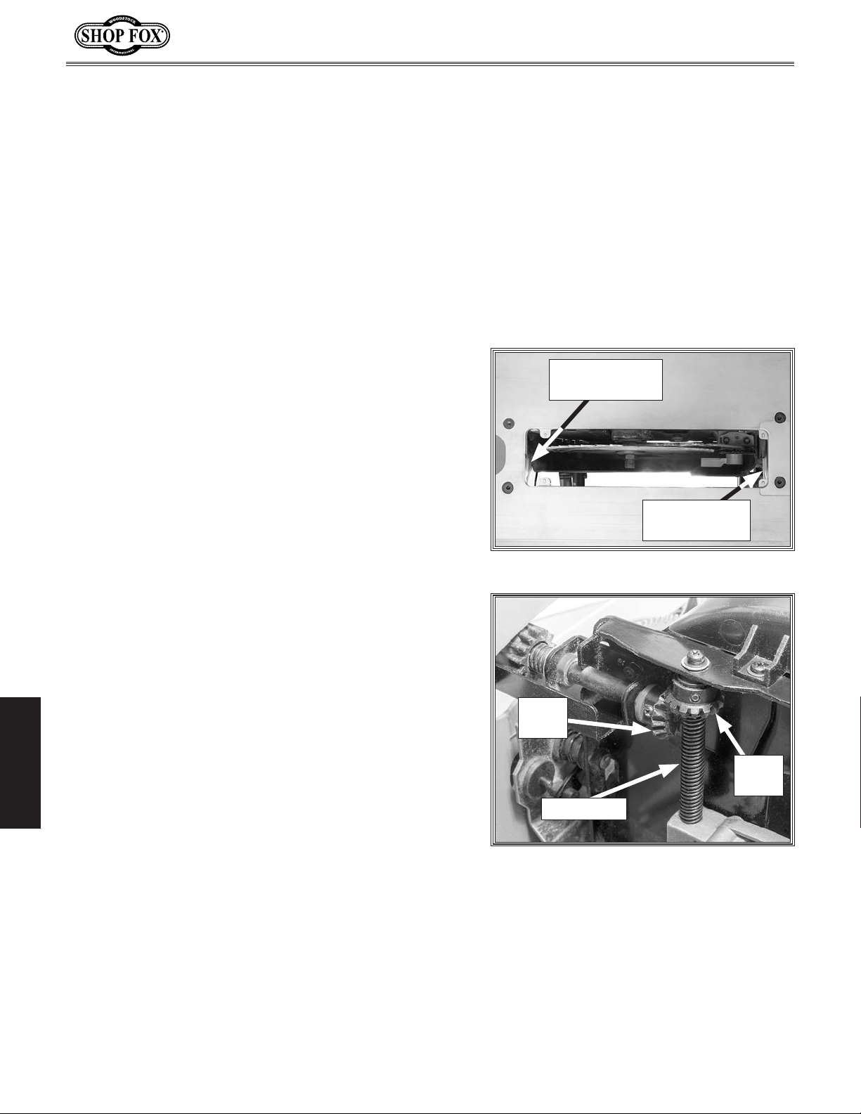
Lubrication
It is essential to clean components before lubricating
them because dust and chips build up on lubricated
components and make them hard to move. Simply adding
more grease to them will not yield smooth moving
components.
Clean the components in this section with mineral spirits
or other oil/grease solvent cleaner and shop rags.
If you thoroughly clean the components in this section
before lubricating them, the result will be silky smooth
movement when turning the handwheels, which will result
in much higher enjoyment on your part!
The following are the main components that need to be
lubricated:
• Trunnion Slides
• Blade Height Worm & Bevel Assemblies
Model W1875 (For Machines Mfd. Since 1/20)
Front Trunnion
Slide
Trunnion Slides
Lubrication Type .............. NLGI#2 Grease or Equivalent
Amount
Lubrication Frequency
Clean out the front and rear trunnion slides with mineral
spirits and a rag, then apply grease into each groove.
Move the blade tilt back and forth to spread the grease
(see Figure
................................................. 1-2 Dabs
........................... 6–12 Months
60).
Blade Height Worm & Bevel Assemblies
Lubrication Type .............. NLGI#2 Grease or Equivalent
Amount
Lubrication Frequency
Clean away any built-up grime and debris from the
worm & bevel assemblies (see Figure
MAINTENANCE
brush, rags, and mineral spirits. Allow the components
to dry, then apply a thin coat of grease to them. Move
components through range of motion to spread grease.
................................................. 1-2 Dabs
........................... 6–12 Months
61) with a wire
Rear Trunnion
Slide
Figure 60. Location of trunnion slides.
Bevel
Gear
Bevel
Gear
Worm Gear
Figure 61. Worm and bevel gears.
-48-
Page 53
Model W1875 (For Machines Mfd. Since 1/20)
This section covers the most common service adjustments
or procedures that may need to be made during the life
of your machine.
If you require additional machine service not included
in this section, please contact Woodstock International
Technical Support at (360) 734-3482 or send e-mail to:
[email protected].
SERVICE
General
Blade Angle Indicator
The blade angle indicator has been set by the factory
to show 0° when the blade is at 90° and should require
no adjustments unless you notice that your cuts are not
accurate.
Tools Needed Qty
90° Square .......................................................1
Phillips Head Screwdriver #2
To adjust blade angle indicator alignment, do these
steps:
1. DISCONNECT MACHINE FROM POWER!
Raise blade as high as it will go, then tilt it toward 0°
2.
until it stops and cannot be tilted any more.
3. Place 90° square against table and blade so it contacts
blade evenly from bottom to top, as shown in F
62. Make sure blade tooth does not obstruct placement of square.
..................................1
igure
MAKE SURE that your machine is
unplugged during all service procedures! If this warning is ignored, serious personal injury may occur.
Blade
Table
Figure 62. Checking blade at 90°.
Adjustment
Screw
90° Square
— If blade is 90° to table and blade angle indicator
points to 0°, then no adjustment is necessary.
— If blade is not 90° to table or blade angle
indicator does not point to 0°, proceed to
4. Tilt blade to 90° using square as a guide. Close blade
angle lock lever to hold blade angle in place.
5. Loosen adjustment screw on blade angle indicator and
reposition indicator to point to 0°. Tighten adjustment
screw (see Figure 63).
Step 4.
-49-
SERVICE
Blade Angle
Indicator
Figure 63. Blade angle indicator
adjustment.
Page 54
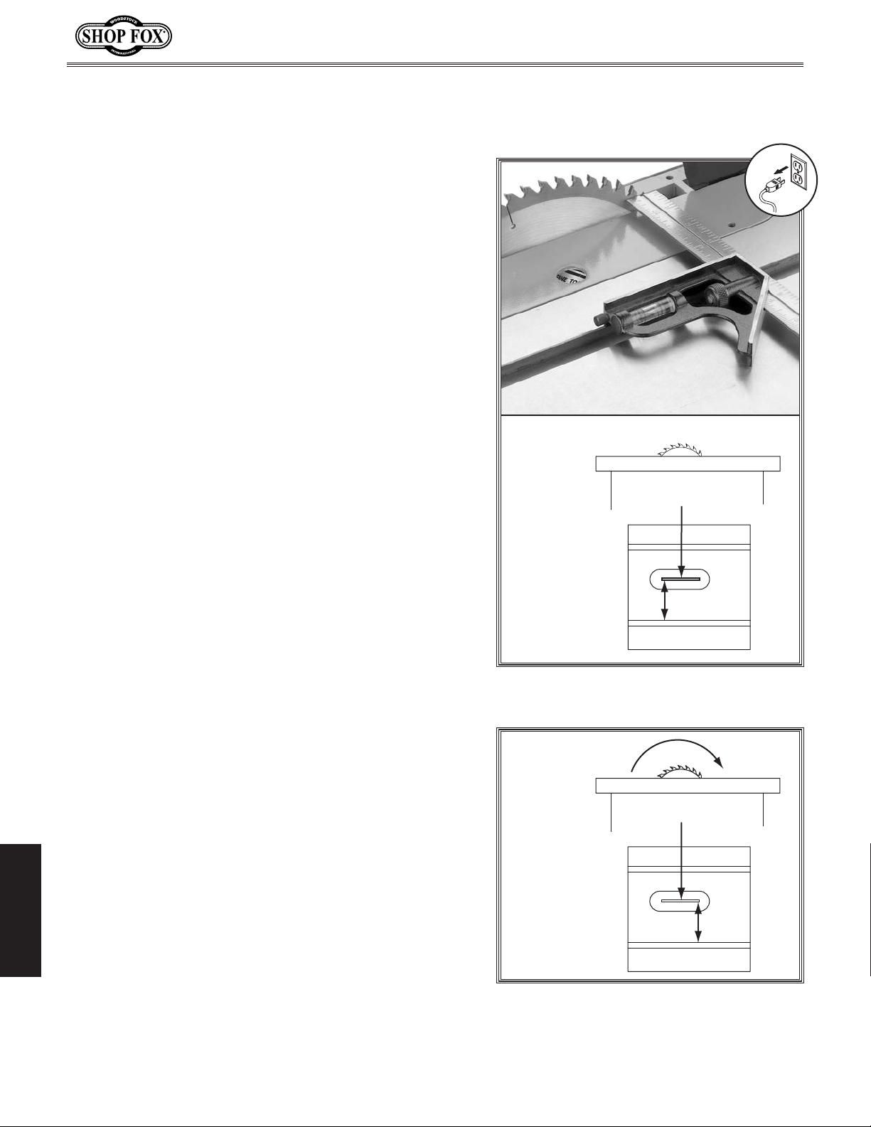
Miter Slot to Blade
Parallelism
Your table saw will give the best results if the miter slot
is adjusted parallel to the blade. If the miter slot is not
exactly parallel, your cuts and your finished work will be
lower in quality, but more importantly, the risk of kickback
will be increased.
Tools Needed Qty
Adjustable Square ..............................................1
Marker
Hex Wrench 5mm
To adjust blade parallel to miter slot, do these steps:
1. DISCONNECT MACHINE FROM POWER!
2.
............................................................1
...............................................1
Tilt blade to 0°, then use an adjustable square to
measure distance from miter slot to a carbide tip on
blade, as shown in Figure 64. Make sure that face of
adjustable square is even along miter slot.
Model W1875 (For Machines Mfd. Since 1/20)
STEP A
Blade tilted to 90º
With end of adjustable square just touching tip,
3.
lock square in place. Now, mark carbide tip with a
marker where you made this measurement.
Rotate marked blade tip to other end of table insert.
4.
5. Slide adjustable square down to other end of table
insert and compare distance from marked blade tip
to end of adjustable square, as shown in
— If blade tip measurement is equal on both sides,
your blade is parallel to the miter slot.
If blade tip does not touch end of adjustable
—
square similar to first measurement, table will
need to be adjusted. Proceed to
Step 6.
SERVICE
Figure 65.
Front
A
Figure 64. Making first slot-to-blade
measurement at 90°.
STEP B
Blade tilted to 90º
Front
B
-50-
Figure 65. Making second slot-to-blade
measurement at 90°.
Page 55
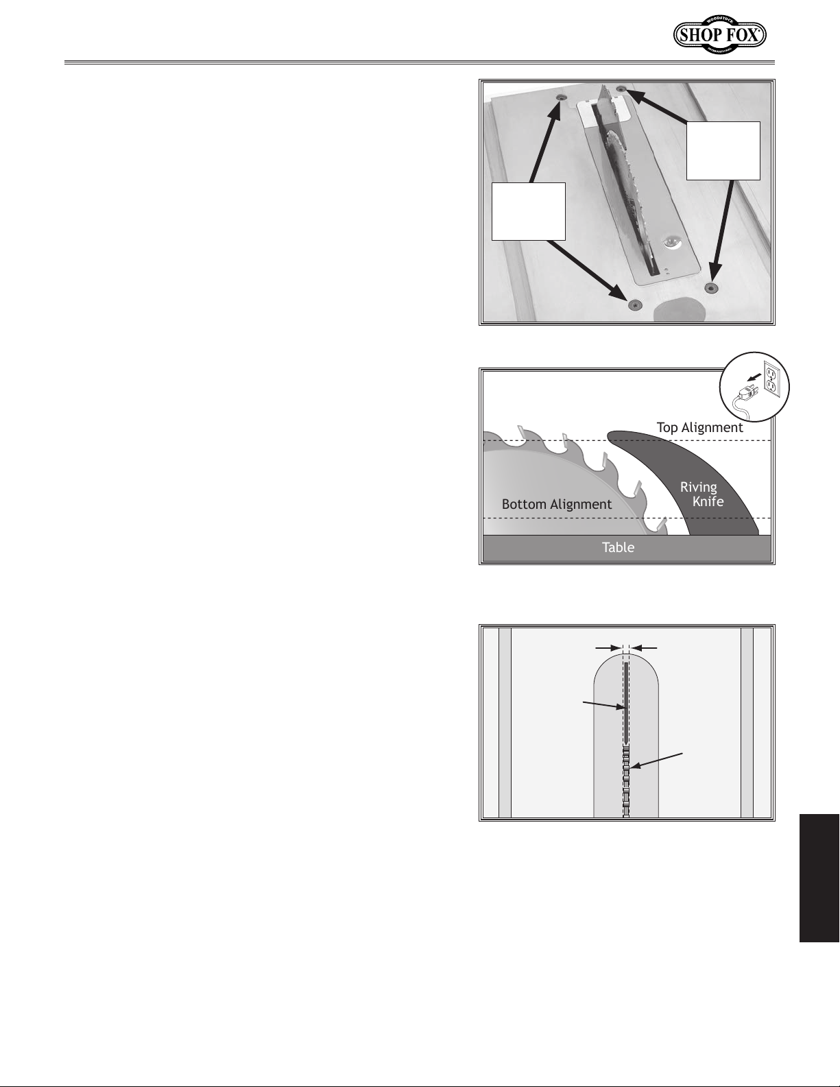
Model W1875 (For Machines Mfd. Since 1/20)
Table
Riving
Knife
Top Alignment
Bottom Alignment
6. Loosen (4) trunnion mounting bolts on table as
shown in
Figure 66.
Move the trunnion assembly in the direction needed
7.
by gently pushing the blade height handwheel or the
dust port. Tighten the trunnion mounting bolts.
Repeat Steps 4-7 until the blade and miter slot are
8.
parallel.
Spreader or Riving Knife
Alignment
Checking Alignment
The blade guard spreader/riving knife must be aligned
with the blade when installed. If the spreader/riving knife
is not aligned with the blade, then the workpiece will be
forced sideways during the cut, which will increase the
risk of kickback.
Tools Needed Qty
Straightedge (min. 12") ........................................1
Trunnion
Mounting
Bolt
Trunnion
Mounting
Bolt
Figure 66. Trunnion mounting bolts.
To check spreader/riving knife alignment, do these
steps:
DISCONNECT MACHINE FROM POWER!
1.
2. Raise saw blade to maximum height so you have easy
working access.
Place straightedge against side of blade and
3.
spreader/riving knife at top and bottom, as shown in
Figure 67. Spreader/riving knife should be parallel
with blade along its length at both positions, and in
"Alignment Zone," as shown in Figure 68.
— If spreader is in alignment zone no adjustments
need to be made.
— If spreader/riving knife is not parallel with blade
and inside alignment zone, then it needs to
be adjusted. Proceed to Adjusting Alignment
instructions.
— If spreader/riving knife is not parallel with the
blade at either the top or bottom, it may be bent.
Figure 67. Example of checking top and
bottom riving knife parallelism with blade.
Alignment
Zone
Spreader or
Riving Knife
Blade
Figure 68. Spreader/riving knife alignment
zone.
4. Remove spreader/riving knife and
place it on flat surface and check to
see if spreader/riving knife lays evenly
along its length.
— If spreader/riving knife does not lay
evenly, proceed to Adjusting Bent
Spreader/Riving Knife on
Page 52.
SERVICE
-51-
Page 56
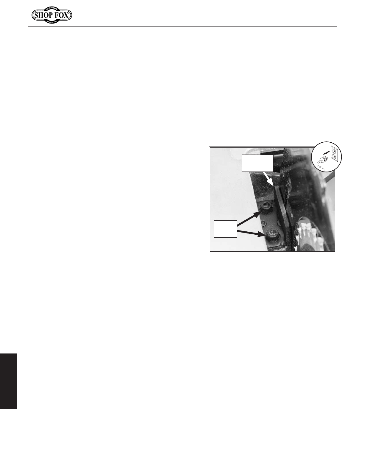
Adjusting Alignment
The spreader/riving knife mounting position can be
adjusted into alignment with the blade using the cap
screws on the spreader/riving knife bracket.
Tools Needed Qty
Hex Wrench 4mm ...............................................1
To adjust spreader/riving knife position, do these steps:
DISCONNECT MACHINE FROM POWER!
1.
Raise blade all the way up then remove table insert.
2.
. Loosen (2) cap screws on the spreader/riving knife
3
bracket (see
knife as needed to move it into alignment with
blade.
. Follow Checking Alignment, Steps 1–3 on Page 51.
4
Figure 69), then slide spreader/riving
Model W1875 (For Machines Mfd. Since 1/20)
Spreader
Bracket
— If spreader/riving knife is in alignment zone, no
additional steps are necessary.
— If spreader is not in alignment zone, continue
adjusting position of spreader/riving knife bracket
as necessary to correctly align spreader/riving
knife.
Tighten (2) cap screws on spreader bracket to secure
5.
spreader/riving knife adjustment.
. Replace table insert.
6
Adjusting Bent Spreader/Riving Knife
1. DISCONNECT MACHINE FROM POWER!
. Bend spreader/riving knife by hand while installed,
2
then follow
Page 51 to determine if it is parallel with blade and
inside "Alignment Zone".
— If this does not work, remove spreader/riving knife
to straighten.
Steps 1–3 in Checking Alignment on
Cap
Screws
Figure 69. Cap screws for adjusting
spreader/riving knife position.
SERVICE
— If you cannot straighten spreader/riving knife prop-
erly, replace it.
-52-
Page 57
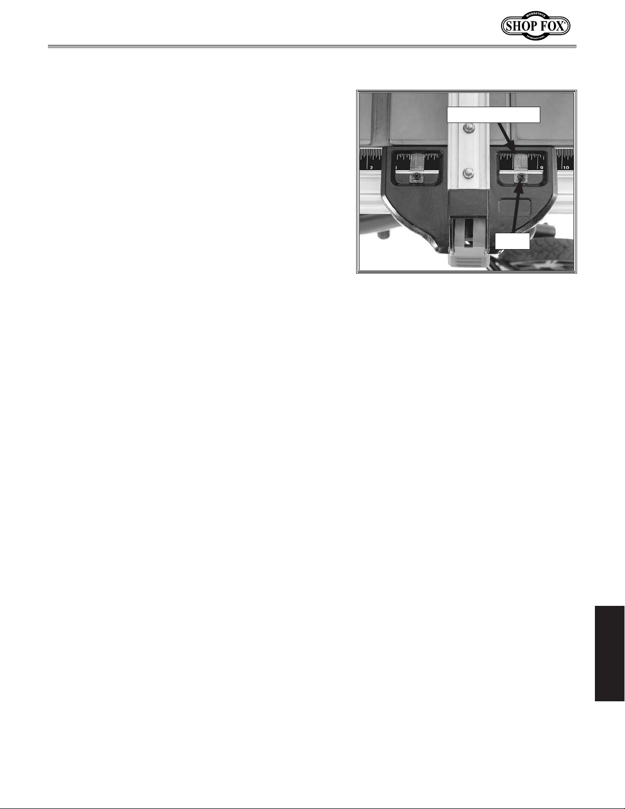
Model W1875 (For Machines Mfd. Since 1/20)
Fence Scale Calibration
The fence scale indicator window, shown in Figure 70,
can be calibrated with the fence scale if you notice that
your cuts do not accurately match what is shown on the
fence scale.
Tools Needed Qty
Phillips Head Screwdriver #2 ..................................1
Scrap Wood (14" Min. Length)
Tape Measure
To calibrate fence scale indicator windows, do these
steps:
Position and lock fence at 13", as indicated by scale,
1.
then cut your scrap piece of wood.
Reposition and lock fence at 12", as indicated by
2.
scale.
....................................................1
................................1
Indicator Window
Screw
Figure 70. Fence indicator window.
Flip your scrap piece of wood over, placing side that
3.
was cut in
piece of wood.
Measure width of freshly cut workpiece with tape
4.
measure. Workpiece width should be exactly 12". If
it is not, then adjust indicator window to match the
width of workpiece.
Step 2 against fence, and cut your scrap
SERVICE
-53-
Page 58
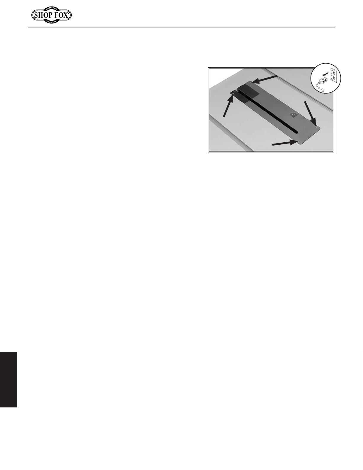
Table/Dado Insert
Adjustment
The table/dado insert must sit perfectly flush with the
table to provide a smooth, continuous surface for the
workpiece to slide over. The insert is held in place by
a magnet and sits on top of four adjustment screws
(see Figure 71).
The insert should be checked and adjusted any time it is
removed and replaced, after prolonged use, or any time
you notice the workpiece or fence does not slide smoothly
over the insert.
Model W1875 (For Machines Mfd. Since 1/20)
Tools Needed Qty
Hex Wrench 4mm ...............................................1
Straightedge
To check and adjust table insert, do these steps:
1. DISCONNECT MACHINE FROM POWER!
2. Place straightedge across insert and make sure insert
is flush with table at front and back of throat.
— If insert is flush with table, no adjustments are
— If insert is not flush with table, proceed to Step 3.
Insert hex wrench through holes shown in Figure 71.
3.
Loosen screws to raise insert, or tighten screws to
lower it.
4. Repeat Steps 2–3 until insert is perfectly flush with
surface of table.
.....................................................1
necessary.
Figure 71. Location of table/dado insert
holes with adjustment screws.
Note: Table insert should be firmly installed (should
not rock) in the table. Each screw should support
insert evenly.
SERVICE
-54-
Page 59
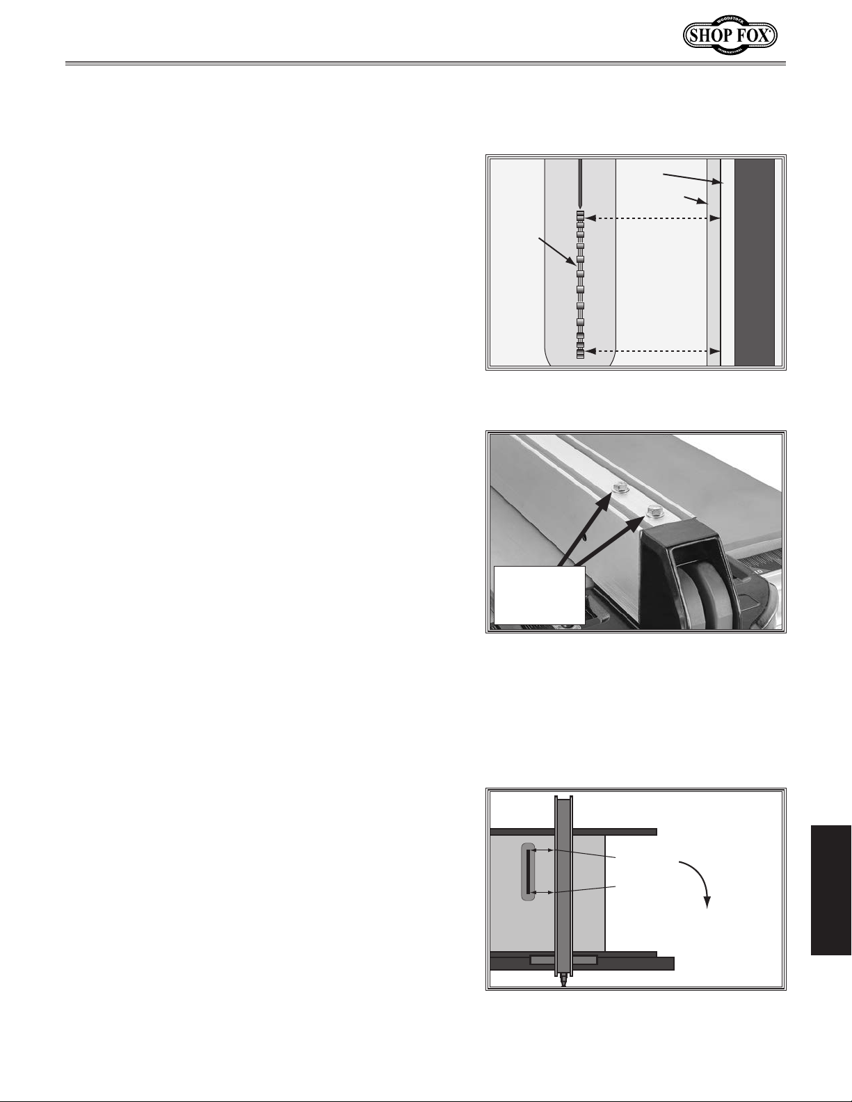
Model W1875 (For Machines Mfd. Since 1/20)
Calibrating Fence to
Blade
Two hex bolts on top of the fence position it parallel with
the blade (see
check the fence/blade parallelism and adjust the fence if
necessary.
Tools Needed Qty
Socket or Wrench 8mm ........................................1
..............................................................1
Ruler
To check and adjust fence parallelism, do these steps:
1. DISCONNECT MACHINE FROM POWER!
Slide fence against right edge of miter slot, lock it in
2.
place, then raise blade fully. Using a ruler, examine
how fence lines up with miter slot and blade (see
Figure 72).
— If fence is parallel with blade, no further
adjustments need to be made.
— If fence is not parallel with blade, proceed to
Step 3.
Unlock fence from table.
3.
4. Loosen two hex bolts on top of fence, as shown in
Figure 73.
Figure 73). Follow the procedures below to
Fence
Miter Slot
Blade
Figure 72. Checking fence parallelism with
Fence
Adjustment
Hex Bolts
Figure 73. Location of hex nuts to adjust
fence parallelism.
Fence is
Parallel to
Miter Slot,
which is
Parallel to
Blade
blade.
Hold fence parallel to blade and tighten hex bolts.
5.
6. Lock fence and measure parallelism with blade.
Repeat Steps 3—6 as needed.
Offsetting Fence
Some woodworkers prefer to offset the rear of the fence
1
/64" from the blade, as shown in Figure 74.
The reason for this wider gap at the back side of the
blade is to help prevent the chance of kickback and the
blade burning the workpiece because a workpiece may be
inconsistent. H o we v er, t h e trade-off is less accurate cuts,
and if the fence is placed on the other side of the blade
for other table saw operations, the potential of workpiece
burning and kickback can be increased. Whenever using
a fence, make sure that if an offset has been adjusted in
the fence alignment, you use the fence on the side of the
blade where the offset creates the wide gap.
-55-
X = Your Measurement
1
⁄64"
X" +
X"
Extra Space
to Prevent Binding
Figure 74. Example of adjusting fence
with a
1
⁄64" offset.
SERVICE
Page 60
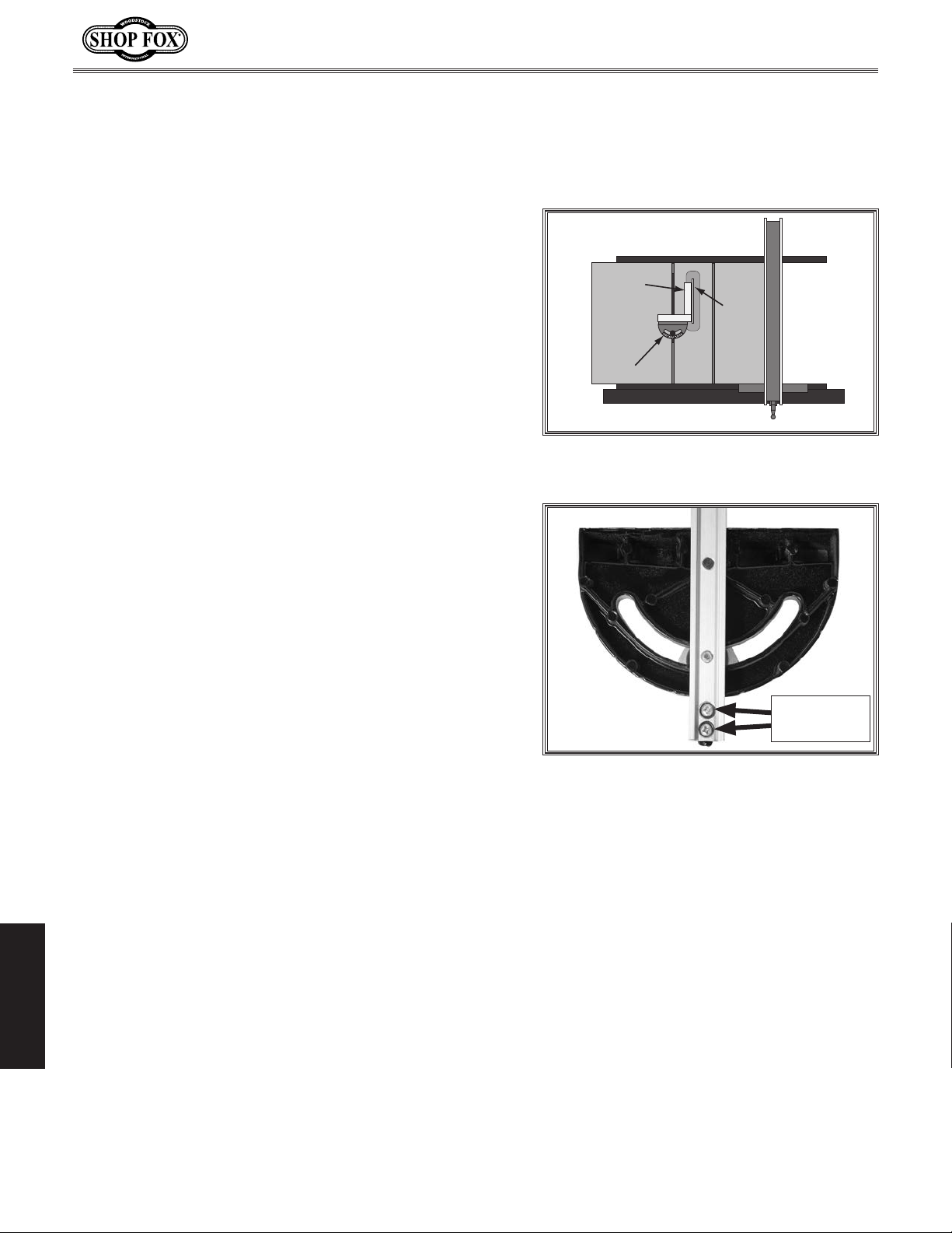
Miter Gauge Adjustments
The miter gauge has quick stops set at -60°, -45°, -30°,
0°, 30°, 45°, and 60° and should require no adjustments
unless you notice that your cuts are not accurate.
Tools Needed Qty
Phillips Head Screwdriver #2 ..................................1
90° Square
To check miter gauge alignment, do these steps:
1. DISCONNECT MACHINE FROM POWER!
.......................................................1
Model W1875 (For Machines Mfd. Since 1/20)
Square
Blade
2. Slide miter gauge into T-slot on table and set to 90°.
3. Place square evenly against face of miter gauge and
blade, as shown in Figure 75.
— If square touches miter body and body of blade
evenly at same time, then it is square to blade. No
adjustments are necessary.
— If square does not touch miter body and blade
evenly, then proceed to
Using a square, position miter shaft at 90° to miter
4.
gauge body.
Remove miter gauge from T-slot and loosen (2) Phillips
5.
head screws that secure miter gauge indicator (see
Figure 76).
Adjust indicator so it lines up with 0° mark on miter
6.
gauge scale, then tighten Phillips head screws.
Step 4.
Miter Gauge
Figure 75. Checking 90° stop on miter
gauge.
Adjustment
Screws
Figure 76. Location of miter gauge
adjustment screws.
SERVICE
-56-
Page 61
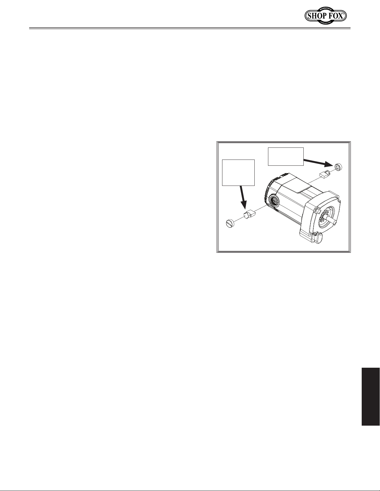
Model W1875 (For Machines Mfd. Since 1/20)
Brush Replacement
This table saw is equipped with a universal motor that
uses two carbon brushes to transmit electrical current
inside the motor. These brushes are considered to be
regular "wear items" or "consumables" that will need to
be replaced during the life of the motor. The frequency
of required replacement is often related to how much the
motor is used and how hard it is pushed.
Replace the carbon brushes (part number X18750726) at
the same time when the motor no longer reaches full
power, or when the brushes measure less than
(new brushes are
we recommend keeping extra brushes on hand to avoid
downtime when the brushes wear out.
Tools Needed Qty
Flat Head Screwdriver 1⁄4" ....................................1
5
⁄8" long). If saw will see daily use,
1
⁄4" long
Motor
Brush
(1 of 2)
Brush Cap
(1 of 2)
To inspect and replace motor brushes, do these steps:
1. DISCONNECT MACHINE FROM POWER!
2. Remove brush caps and worn brushes from motor
Figure 77).
(see
Replace both motor brushes, then install brush caps.
3.
Figure 77. Motor brush replacement.
SERVICE
-57-
Page 62
Model W1875 (For Machines Mfd. Since 1/20)
The following troubleshooting tables cover common problems that may occur with this machine. If you
need replacement parts or additional troubleshooting help, contact our Technical Support.
Note:
available, your original purchase receipt. This information is required to properly assist you.
Troubleshooting
Before contacting Tech Support, find the machine serial number and manufacture date, and if
Motor & Electrical
PROBLEM POSSIBLE CAUSE CORRECTIVE ACTION
Machine does not
start, or powersupply fuse/breaker trips immediately after startup.
Machine stalls or
is underpowered.
Machine has
vibration or noisy
operation.
1. Switch disabling key removed.
2. Machine circuit breaker tripped.
3. Power supply circuit breaker tripped or fuse
blown.
4. Wiring broken, disconnected, or corroded.
5. Motor brushes worn out.
6. ON/OFF or circuit breaker switch at fault.
7. Motor at fault.
1. Workpiece material unsuitable for machine.
2. Feed rate too aggressive for motor blade.
3. Workpiece crooked; fence not parallel with
blade.
4. Blade dull or wrong blade for task.
5. Motor brushes worn out.
6. Motor overheated.
7. Motor or motor bearings at fault.
1. Motor or component loose.
2. Mobile stand fasteners loose or feet not
adjusted properly.
3. Blade damaged or warped.
4. Arbor bearings at fault.
5. Motor bearings at fault.
1. Insert switch disabling key.
2. Reset circuit breaker on switch.
3. Ensure circuit is free of shorts. Reset circuit break-
er or replace fuse (Page 13).
4. Fix broken wires or disconnected/corroded connections.
5. Replace motor brushes (Page 57).
6. Replace switch/circuit breaker.
7. Replace motor.
1. Only cut wood; ensure moisture is below 20%.
2. Reduce feed pressure and speed.
3. Use jointer to straighten edge of workpiece that
slides against fence; adjust fence parallel with
blade (
Page 55).
4. Use correct blade for type of cut (Page 25). Use
sharp blade.
5. Replace motor brushes (Page 57).
6. Clean motor, let cool, and reduce workload.
7. Replace motor.
1. Replace missing bolts/nuts or tighten if loose.
2. Tighten machine to mobile stand or adjust feet to
stabilize machine.
3. Replace warped/damaged blade (Page 27).
4. Replace arbor housing bearings; replace arbor.
5. Test by rotating shaft; grinding/loose shaft requires
bearing replacement.
SERVICE
-58-
Page 63
Model W1875 (For Machines Mfd. Since 1/20)
Operation
PROBLEM POSSIBLE CAUSE CORRECTIVE ACTION
Fence does not
move smoothly.
Material moves
away from fence
when ripping.
Blade not parallel with miter
slot.
Blade hits table
insert when tilting to 45°.
Blade too close
to insert.
Board binds or
burns when feeding through saw.
Handwheel binds
or blade will not
move up/down or
tilt freely.
Too much sawdust blown back
toward operator.
1. Fence not mounted/adjusted correctly.
2. Rails dirty or sticky.
1. Improper feeding technique.
2. Fence not parallel with blade.
3. Workpiece crooked or bowed.
1. Blade is damaged or warped.
2. Table misadjusted.
1. Sawdust/debris stuck in trunnion slides.
2. Miter slot not parallel with blade.
3. Blade incorrectly installed.
1. Blade position on arbor is incorrect.
2. Table/trunnion assembly mounting position
not correct.
1. Board warped.
2. Feed rate too slow or inconsistent.
3. Blade is warped/damaged/dull.
4. Too many teeth on blade for cutting type.
5. Fence not parallel with blade.
6. Miter slot not parallel with blade.
7. Spreader/riving knife not correctly aligned
with blade.
1. Lock knob is engaged.
2. Sawdust/debris stuck in trunnion slides.
1. Dust collector not turned on or connected.
2. Blade guard has been removed.
3. Dust collection system clogged or lacks
required CFM at machine.
1. Remount fence and adjust correctly.
2. Clean and lubricate/wax rails.
1. Learn/use proper feeding technique.
2. Adjust fence parallel with blade (Page 55).
3. Use jointer to straighten edge of workpiece that
slides against fence.
1. Replace blade (Page 27).
2. Adjust miter slot parallel with blade (Page 50).
1. Clean sawdust or debris out of trunnion slides.
2. Adjust miter slot parallel with blade (Page 50).
3. Correctly install blade (Page 27).
1. Verify that blade arbor washers are correct and in
the required position.
2. Adjust table mounting position (Page 50).
1. Use a different board or use jointer to straighten
edge of workpiece that slides against fence.
2. Reduce feed rate and apply consistent pressure
through entire cut.
3. Replace blade (Page 27).
4. Change blade to one with fewer teeth (Page 25).
5. Adjust fence parallel with blade (Page 55).
6. Adjust miter slot parallel with blade (Page 50).
7. Adjust spreader/riving knife into alignment with
blade (Page 52).
1. Loosen lock knob.
2. Clean sawdust/debris out of trunnion slides.
1. Connect and turn on dust collector.
2. Re-install blade guard for maximum safety and dust
control (Page 28).
3. Remove clog; revise ducting layout for improved
suction; use a stronger dust collector (Page 20).
-59-
SERVICE
Page 64
Model W1875 (For Machines Mfd. Since 1/20)
PROBLEM POSSIBLE CAUSE CORRECTIVE ACTION
Tooth marks on
cut edge.
Finished board
narrower than
expected.
Kickback occurs.
Miter Gauge
does not move
smoothly.
Will not make
accurate cuts.
1. Blade is warped/damaged/dull.
2. Fence not parallel with blade.
3. Miter slot not parallel with blade.
1. Fence scale pointer not adjusted correctly or
fence scale label misapplied.
1. Fence not parallel with blade.
2. Feeding boards freehand without fence or
miter gauge.
3. Spreader/riving knife not correctly aligned
with blade.
4. Blade guard not installed/not working correctly.
5. Blade warped/damaged/dull.
6. Letting go of board before it is past blade.
7. Board not held firmly against table and fence.
8. Using miter gauge and fence at the same
time.
9. Board is warped or edge that slides against
fence is bowed/curved.
10. Taking too deep of a cut.
1. Bent miter gauge bar; burrs on bar/slot; dirty
slot.
1. Pointer calibrated incorrectly to scale.
2. Miter slot not parallel with blade.
3. Fence not parallel with blade.
1. Replace blade (Page 27).
2. Adjust fence parallel with blade (Page 55).
3. Adjust miter slot parallel with blade (Page 50).
1. Adjust fence scale pointer (Page 53) or re-apply
fence scale label in correct position.
1. Adjust fence parallel with blade (Page 55).
2. Always use fence or miter gauge as a guide when
feeding workpiece.
3. Adjust spreader/riving knife into alignment with
blade (Page 51).
4. Install blade guard (Page 28). Replace blade guard
before using saw if damaged.
5. Replace blade (Page 27).
6. Move board completely past blade before releasing
7. Hold board firmly against table and fence; use push
stick(s) whenever possible to keep fingers away
from blade.
8. Never use miter gauge and fence together. Always
use one or the other.
9. Always cut bowed workpiece with cupped side
against table; use a jointer to straighten edge of
board that slides against fence (
10. Always take multiple shallow passes for nonthrough cuts.
1. Straighten/replace bar; deburr bar or slot; clean
debris from slot.
1. Adjust blade 90° to table using a square, then calibrate pointer to scale.
2. Adjust miter slot parallel with blade (Page 50).
3. Adjust fence parallel with blade (Page 55).
Page 12).
SERVICE
-60-
Page 65
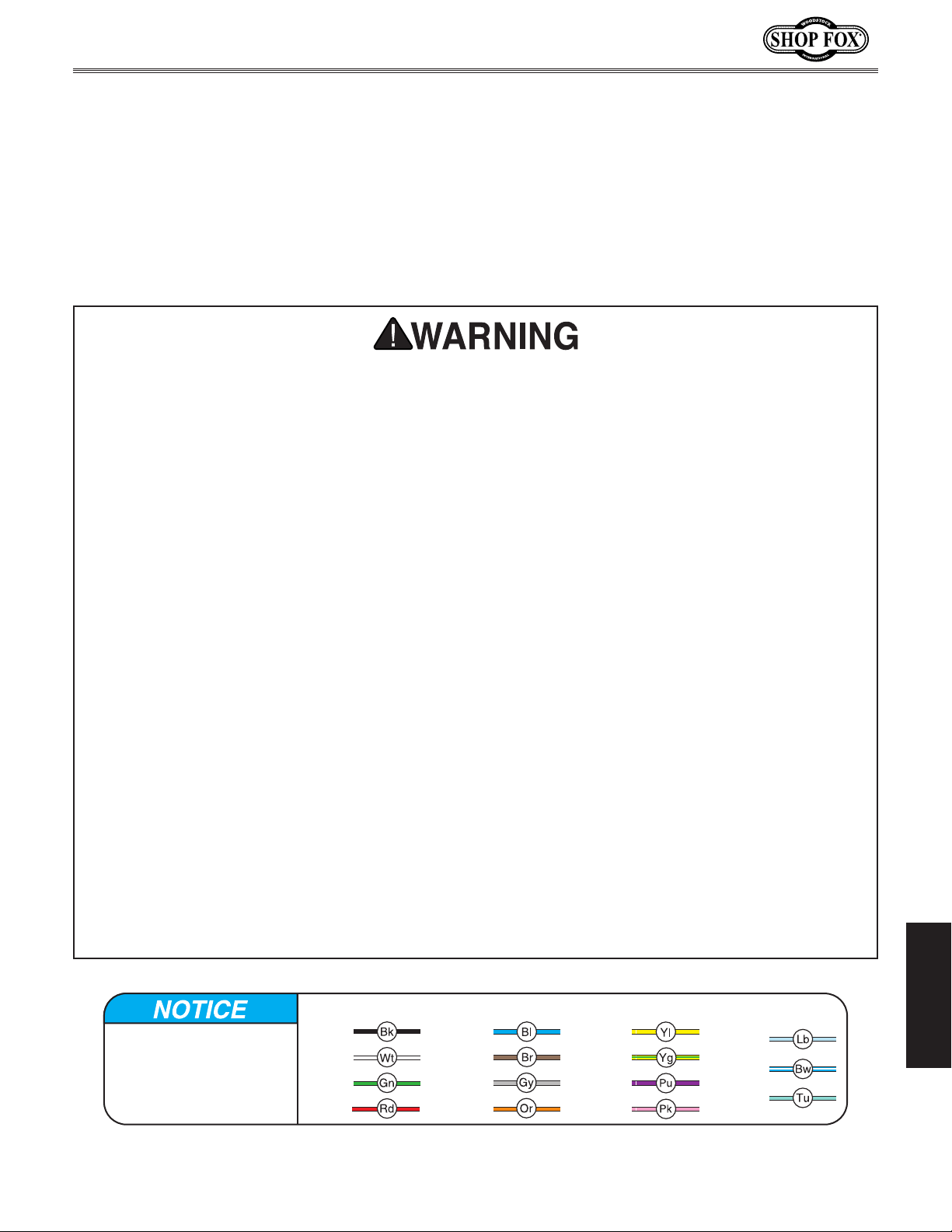
Model W1875 (For Machines Mfd. Since 1/20)
These pages are current at the time of printing. However, in the spirit of improvement, we may make
changes to the electrical systems of future machines. Compare the manufacture date of your machine to
If there are differences between your machine and what is shown in this section, call Technical Support
for assistance BEFORE making any changes to the wiring on your machine. An updated
machine before calling. This information can be found on the main machine label.
Electrical Safety Instructions
the one stated in this manual, and study this section carefully.
at (360) 734-3482
wiring diagram may be available. Note: Please gather the serial number and manufacture date of your
SHOCK HAZARD. Working on wiring that is
connected to a power source is extremely
dangerous. Touching electrified parts will
result in personal injury including but not
limited to severe burns, electrocution,
or death. Disconnect the power from
the machine before servicing electrical
components!
QUALIFIED ELECTRICIAN. Due to the inherent
hazards of electricity, only a qualified
electrician should perform wiring tasks on
this machine. If you are not a qualified
electrician, get help from one before
attempting any kind of wiring job.
WIRE CONNECTIONS. All connections must
be tight to prevent wires from loosening
during machine operation. Double-check all
wires disconnected or connected during any
wiring task to ensure tight connections.
WIRE/COMPONENT DAMAGE. Damaged wires
or components increase the risk of serious
personal injury, fire, or machine damage. If
you notice that any wires or components are
damaged while performing a wiring task,
replace those wires or components before
completing the task.
MODIFICATIONS. Using aftermarket parts or
modifying the wiring beyond what is shown
in the diagram may lead to unpredictable
results, including serious injury or fire.
MOTOR WIRING. The motor wiring shown
in these diagrams is current at the time
of printing, but it may not match your
machine. Always use the wiring diagram
inside the motor junction box.
CAPACITORS/INVERTERS. Some capacitors
and power inverters store an electrical
charge for up to 10 minutes after being
disconnected from the power source.
To reduce the risk of being shocked,
wait at least this long before working on
capacitors.
CIRCUIT REQUIREMENTS. You MUST follow
the requirements at the beginning of this
manual when connecting your machine to a
power source.
EXPERIENCING DIFFICULTIES. If you are
experiencing difficulties understanding
the information included in this section,
contact our Technical Support at
(360) 734-3482.
SERVICE
WIRING DIAGRAM COLOR KEY
The photos and diagrams
included in this section are
best viewed in color. You
can view these pages in
color at www.shopfox.biz.
BLACK
WHITE
GREEN
RED
BLUE
BROWN
GRAY
ORANGE
-61-
YELLOW
YELLOW
GREEN
PURPLE
PINK
LIGHT
BLUE
BLUE
WHITE
TURQUOISE
Page 66
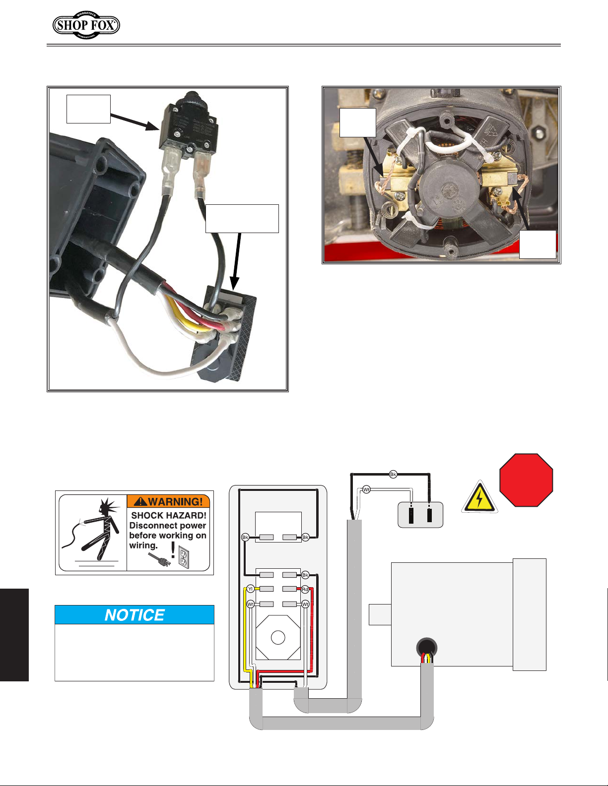
The motor wiring shown here is
current at the time of printing, but it
may not match your machine. Always
use the wiring diagram inside the
1-15 Plug
Switch Box
Circuit
Breaker
Model W1875 (For Machines Mfd. Since 1/20)
Electrical Components
Motor
Brush
ON/OFF
Button Switch
Motor
Brush
Figure 79. Motor brushes.
Figure 78. Switch box wiring.
Wiring Diagram
Read
(viewed from behind)
Button Switch
Circuit
Breaker
L2 Series
15A 125/250VAC
LOAD
LINE
ON/OFF
KEDU 011713
NEUTRAL
HOT
AW
120 VAC
Universal Motor
(120V)
SERVICE
motor junction box.
Page 61
STOP
Before
Wiring
-62-
Page 67
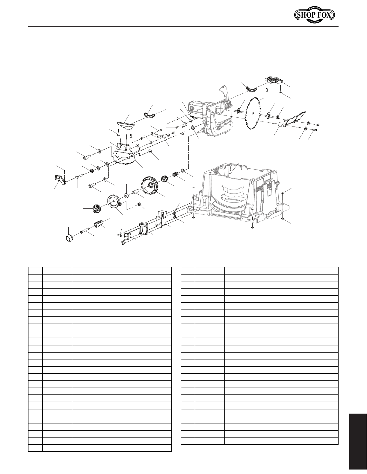
Model W1875 (For Machines Mfd. Since 1/20)
35 X18750035 CAMLOCK STUD M10-1.5
PARTS
Trunnions & Blade
19
20
26
25
29
31
44
45
53
36
37
50
33
34
35
47
32
60
21
28
30
60
40
32
33
46
51
48
49
52
43
24
27
23
54
22
42
39
56
41
55
40
38
19
57
16
15
12
14
13
18
17
59
11
58
10
REF PA RT # DESCRIPTION REF PA RT # DESCRIPTION
10 X18750010 TAP SCREW M4 X 12 36 X18750036 CAP SCREW M4-.7 X 25
11 X18750011 FENDER WASHER 5MM 37 X18750037 BLADE TILT LOCK HANDLE
12 X18750012 LOWER B LADE GUARD 38 X18750038 HEX NUT M10- 1.5
13 X18750013 ARBOR NUT 5/8" 39 X18750039 SET SCREW M5-.8 X 10
14 X18750014 OUTER ARBOR FLANGE 40 X18750040 FLAT WASH ER 12MM
15 X18750015 SAW B LADE 10" X 36T 41 X18750041 COMPRESSION SPRING
16 X18750016 INNER ARB OR FLANG E 42 X18750042 MICRO ADJUST WHEEL
17 X18750017 TR UNNION MOUNTING SCREW 43 X18750043 BLADE TILT ADJUSTMENT HANDWHEEL
18 X18750018 REAR TRUNNION 44 X18750044 HEIGH T WHEEL CLAMP SLEEVE
19 X18750019 TR UNNION SLIDE 45 X18750045 LOCK NUT M6-1
20 X18750020 FRONT TRUNNION 46 X18750046 BLADE HEIGHT ADJUSTMENT HANDW H EEL
21 X18750021 TR UNNION MOUNTING SCREW 47 X18750047 BLADE HEIGHT LOCK
22 X18750022 PHLP HD SCR M5- .8 X 12 48 X18750048 BLADE HEIGHT H ANDLE GRI P
23 X18750023 TILT INDICATOR BRACKET 49 X18750049 SH OULDER SCREW M6-1 X 10, 8 X 43
24 X18750024 BLADE TILT INDICATOR 50 X18750050 BLADE HEIGHT H ANDLE CAP
25 X18750025 PHLP HD SCR M4- .7 X 12 51 X18750051 TAP SCREW M4 X 16
26 X18750026 CAP SCREW M6-1 X 16 52 X18750052 ON/OFF SW ITCH JIAB EN FD2-12G-2116A 125V
27 X18750027 BLADE TILT LOCK PLATE 53 X18750053 SWITCH BRACKET
28 X18750028 SP ACER 54 X18750054 SWITCH BOX
29 X18750029 BLADE TILT STOP 55 X18750055 STRAIN RELIEF TYPE-3 1/16 – 1/8
30 X18750030 CAP SCREW M5-.8 X 20 56 X18750056 STRAIN RELIEF TYPE-3 1/16 – 1/8
31 X18750031 TR UNNION GEAR P LATE 57 X18750057 FLANGE BOLT M6-1 X 16
32 X18750032 FLAT WASHER 5MM 58 X18750058 B UTTON HD CAP SCR M6-1 X 55
33 X18750033 CAP SCREW M5-.8 X 16 59 X18750059 LOCK NUT M6- 1
34 X18750034 CAM WASHER 60 X18750060 FENDER WASHER 8MM
PARTS
-63-
Page 68
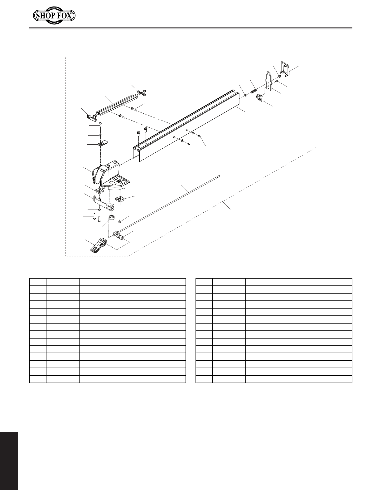
Fence
113 X18750113 FLANGE BO LT M6-1 X 16 127 X18750127 W ING NUT M6- 1
Model W1875 (For Machines Mfd. Since 1/20)
122
104
105
106
108
110
101
102
103
107
123
109
124
113
107
105
111
125
112
126
127
115
100
116
114
120
121
119
118
117
REF PART # DESCRIPTION REF PART # DESCRIPTION
100 X18750100 FENCE ASSEMBLY 114 X18750114 FENCE
101 X18750101 PHLP H D SCR M4-.7 X 10 115 X18750115 FENDER WAS HER 6MM
102 X18750102 FLAT WASHER 4MM 116 X18750116 COMPRESSION SPRING
103 X18750103 INDICATOR 117 X18750117 REAR SLIDER
104 X18750104 FENCE BASE 118 X18750118 CLAMPING PLATE
105 X18750105 FRONT SLIDER 119 X18750119 TAP SCREW M5 X 10
106 X18750106 MICRO ADJUST SUPPORT 120 X18750120 LOCK NUT M6-1
107 X18750107 PHLP H D SCR M5-.8 X 10 121 X18750121 END CAP
108 X18750108 PHLP H D SCR M5-.8 X 25 122 X18750122 FENCE FACE FRONT COVER
109 X18750109 MICRO ADJ UST W HEEL 123 X18750123 FENCE FACE
110 X18750110 FENCE LOCK LEVER 124 X18750124 FENCE FACE REAR CO VER
111 X18750111 LO CK BUSH I NG 125 X18750125 SQUARE NECK SCREW M6- 1 X 50
112 X18750112 LOCK ROD 126 X18750126 FENDER WAS HER 6MM
PARTS
-64-
Page 69
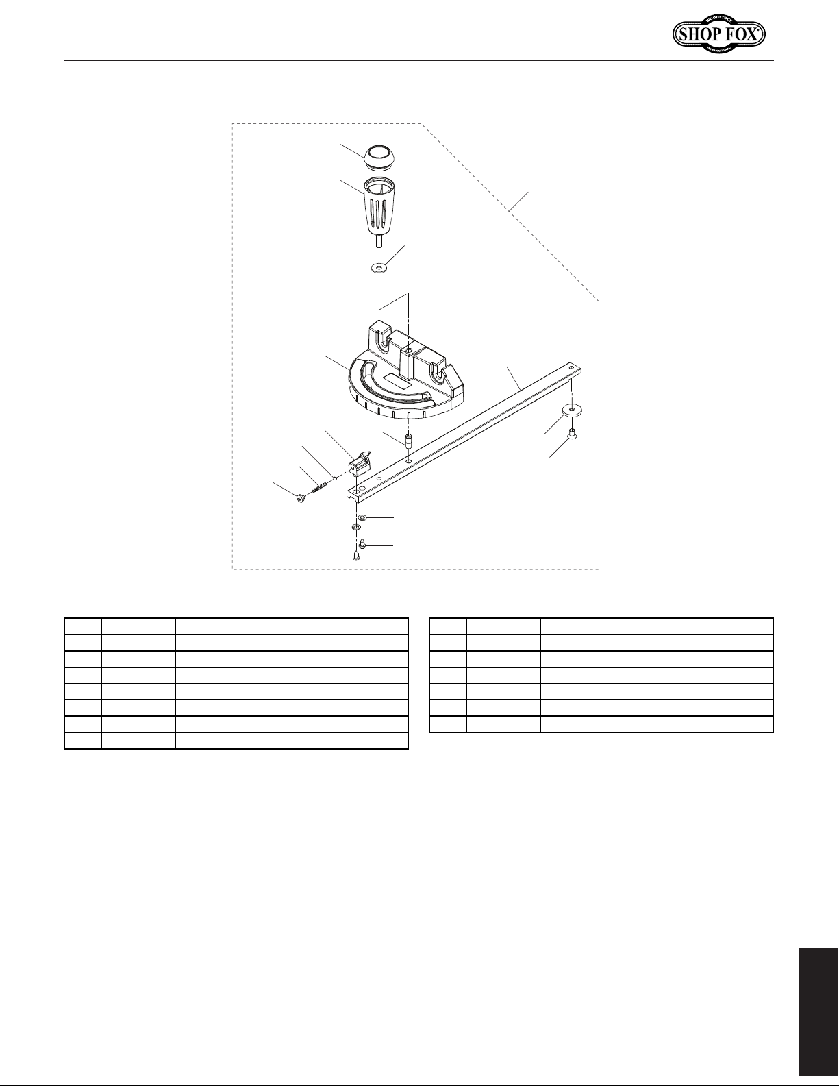
Model W1875 (For Machines Mfd. Since 1/20)
207 X18750207 BALL
Miter Gauge
201
205
207
206
204
208
202
200
203
212
209
213
214
210
211
REF PART # DESCRIPTION REF PART # DESCRIPTION
200 X18750200 MI TER GAUGE ASSEMBLY 208 X18750208 MITER GAUGE INDICATOR
201 X18750201 HANDLE CAP 209 X18750209 MITER HINGE PIN
202 X18750202 FIXED H ANDLE 18 X 33, M6-1 X 10 210 X18750210 FLAT WASHER 4MM
203 X18750203 FENDER WAS HER 6MM 211 X18750211 TAP SCREW M4 X 16
204 X18750204 MI TER GAUGE BODY 212 X18750212 MI TER BAR
205 X18750205 TAP SCREW M5 X 8 213 X18750213 MITER B AR GUIDE WASHER
206 X18750206 COMPRESSION SPRING 214 X18750214 FLAT HD SCR M6-1 X 10
PARTS
-65-
Page 70
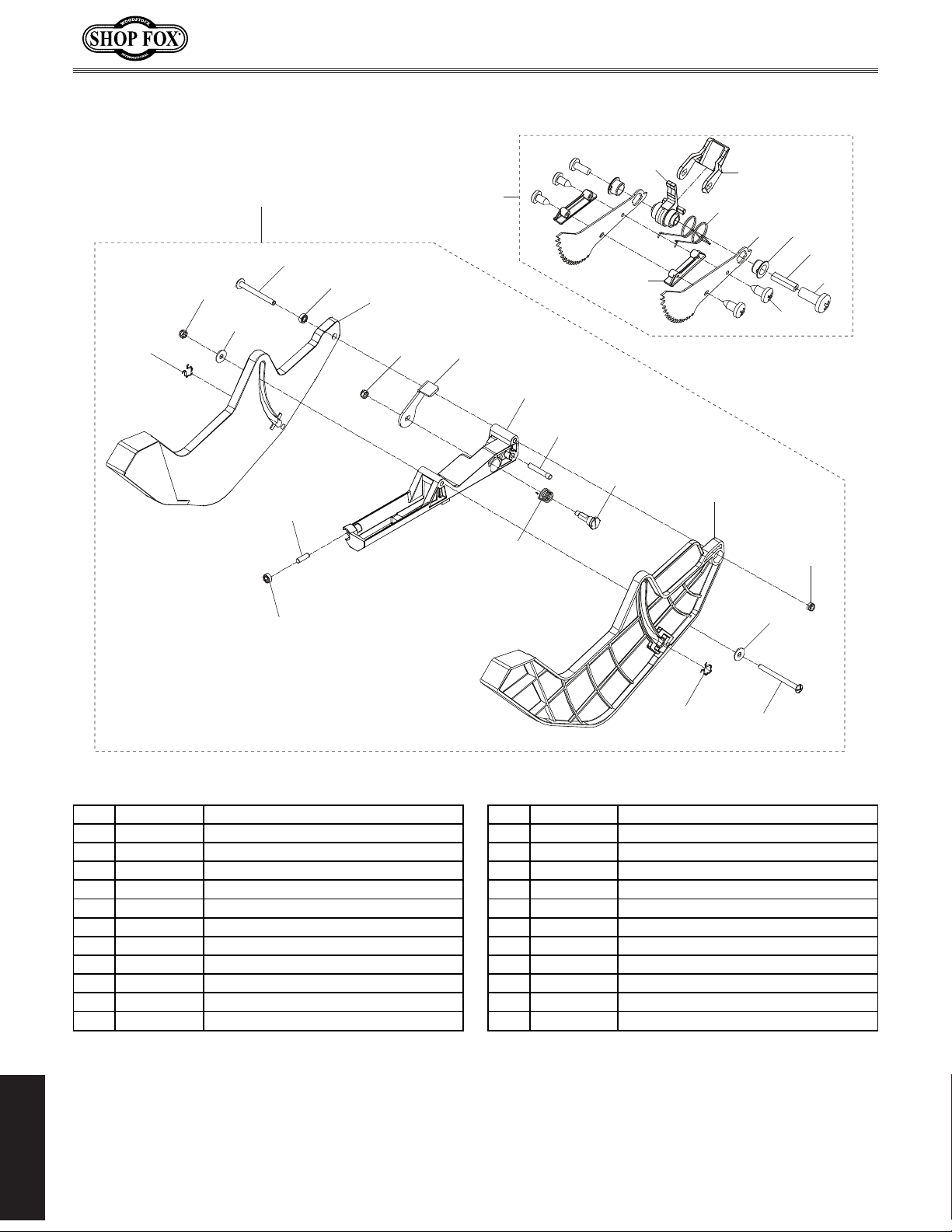
Model W1875 (For Machines Mfd. Since 1/20)
Anti-Kickback Pawls & Blade Guard
403
404
402
400
401
413
412
411
404
410
300
407
409
408
308
406
307
405
305
306
304
303
302
301
309
404
412
403
REF PART # DESCRIPTION REF PART # DESCRIPTION
300 X 18750300 ANTI-KICKBACK PAWLS ASSEMBLY 402 X 18750402 FENDER W ASH ER 5MM
301 X 18750301 PHLP HD SCR M4-.7 X 10 403 X 18750403 COT TER P IN RET AINING
302 X 18750302 PIN 404 X 18750404 LOCK NUT M5-.8
303 X 18750303 BUSHING 405 X 18750405 RIGHT BLADE GUARD
304 X 18750304 ANTI-KICKBACK PAWL 406 X 18750406 PIN
305 X 18750305 TORSION SPRING 407 X 18750407 TORSION SPRING
306 X 18750306 RELEASE LEVER 408 X 18750408 HEADED P IN 5 X 30MM
307 X 18750307 ANTI-KICKBACK PAWL BODY 409 X 18750409 BLADE GUARD S UP P ORT
308 X 18750308 ANTI-KICKBACK PAWL SUPPORT 410 X 18750410 LOCK HANDLE
309 X 18750309 TAP SCREW M4 X 10 411 X18750411 LEFT BLADE GUARD
400 X 18750400 BLADE GUARD ASSEMBLY 412 X 18750412 BALL BEARING
401 X 18750401 PHLP HD SCR M5-.8 X 50 413 X 18750413 PIN 5 X 16MM
402
401
PARTS
-66-
Page 71
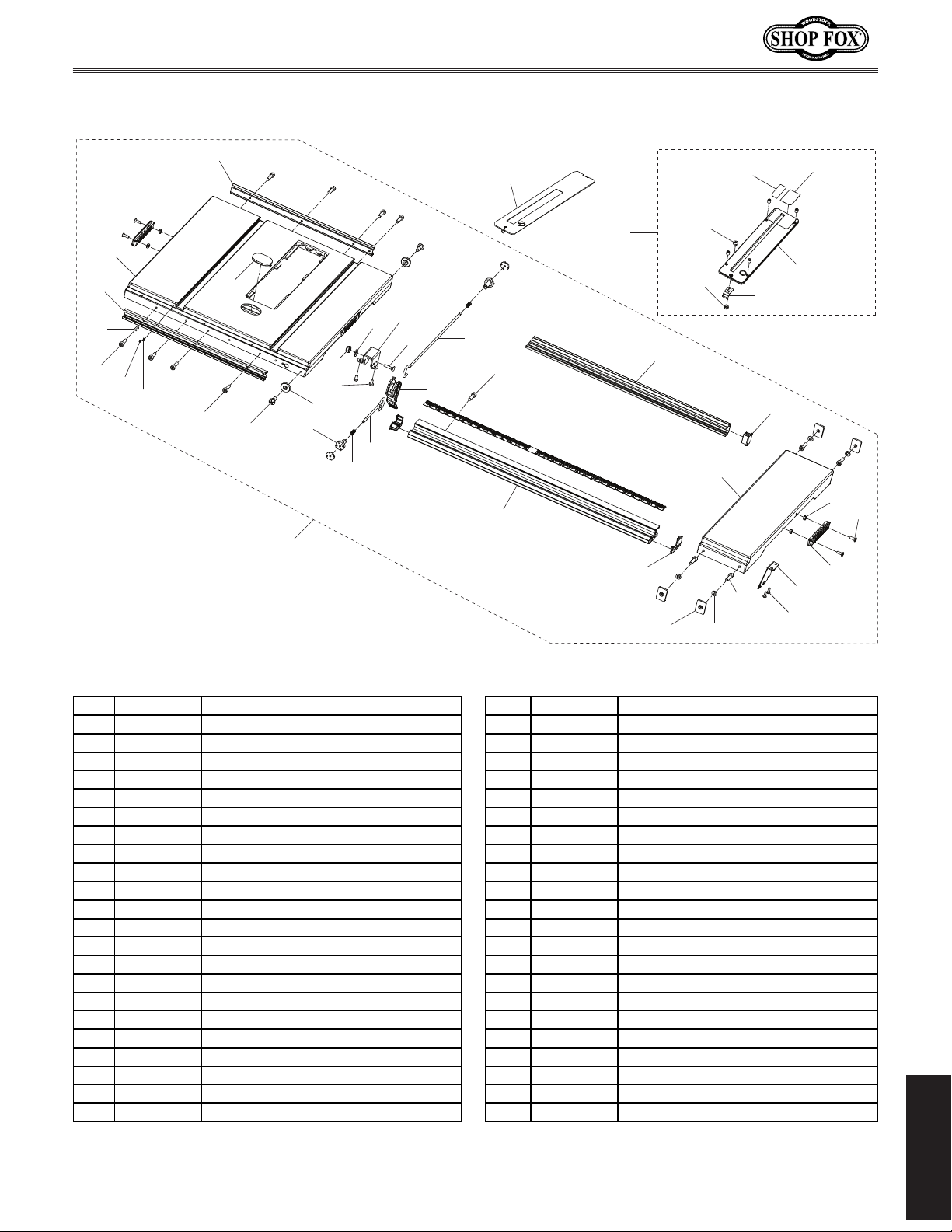
Model W1875 (For Machines Mfd. Since 1/20)
622 X18750622 CARRIAGE BOLT M6-1 X 40 651 X18750651 DADO TABLE INSERT
Table
634
631
630
635
633
632
629
634
636
627
616
600
617
625
626
628
618
624
619
613
623
622
620
621
651
612
611
650
610
606
650-5
650-7
614
650-2
609
607
608
650-1
650-3
650-4
650-6
615
603
601
602
604
605
REF PART # DESCRIPTION REF PAR T # DESCRIPTION
600 X18750600 TABLE ASSEMBLY 623 X18750623 EXTENSI ON ROD H OLDER
601 X18750601 FLAT H D SCR M4- .7 X 12 624 X18750624 FLAT WASHER 6MM
602 X18750602 H ANDLE 625 X18750625 LOC K NUT M6- 1
603 X18750603 HEX NUT M4-.7 626 X18750626 FLAT H D SCR M6-1 X 12
604 X18750604 BLADE GUARD STORAGE BRACKET 627 X18750627 FENCE RO LLER S HOULDER SCREW
605 X18750605 PHLP HD SCR M6-1 X 16 628 X18750628 FENCE RO LLER
606 X18750606 FENCE RAIL NUT 629 X18750629 CAP SCREW M5-.8 X 14
607 X18750607 FENDER W ASH ER 5MM 630 X 18750630 CAP SCREW M5-. 8 X 30
608 X18750608 CAP SCREW M5-.8 X 16 631 X18750631 NUT M6-1
609 X18750609 EXTENSION TABLE 632 X18750632 INDICATOR
610 X18750610 FRONT RAIL END CAP (RH) 633 X18750633 P HLP HD SCR M4-.7 X 12
611 X18750611 FRONT RAIL 634 X18750634 RAIL GUIDE
612 X18750612 CAP SCREW M5-.8 X 10 635 X18750635 TABLE
613 X18750613 FRONT RAI L END CAP (LH) 636 X18750636 ALIGNMENT DIS C
614 X18750614 REAR RAIL 650 X18750650 TABLE INSERT ASSEMBLY
615 X18750615 REAR RAIL END CAP 650-1 X 18750650-1 RIGHT WEAR PLATE
616 X18750616 LOCK PAD 650-2 X18750650-2 LEFT W EAR P LATE
617 X18750617 LOCK BLOCK 650-3 X18750650- 3 SET SCREW M5-.8 X 6
618 X18750618 COMPRESSION SPRING 650-4 X18750650-4 TAB LE INSERT
619 X18750619 FRONT LOCK BAR 650-5 X18750650- 5 PHLP H D SCR M4-.7 X 10
620 X18750620 LOCK LEVER 650-6 X18750650-6 SPRING PLATE
621 X18750621 REAR LOCK BAR 650-7 X18750650-7 LOCK NUT M4-.7
PARTS
-67-
Page 72
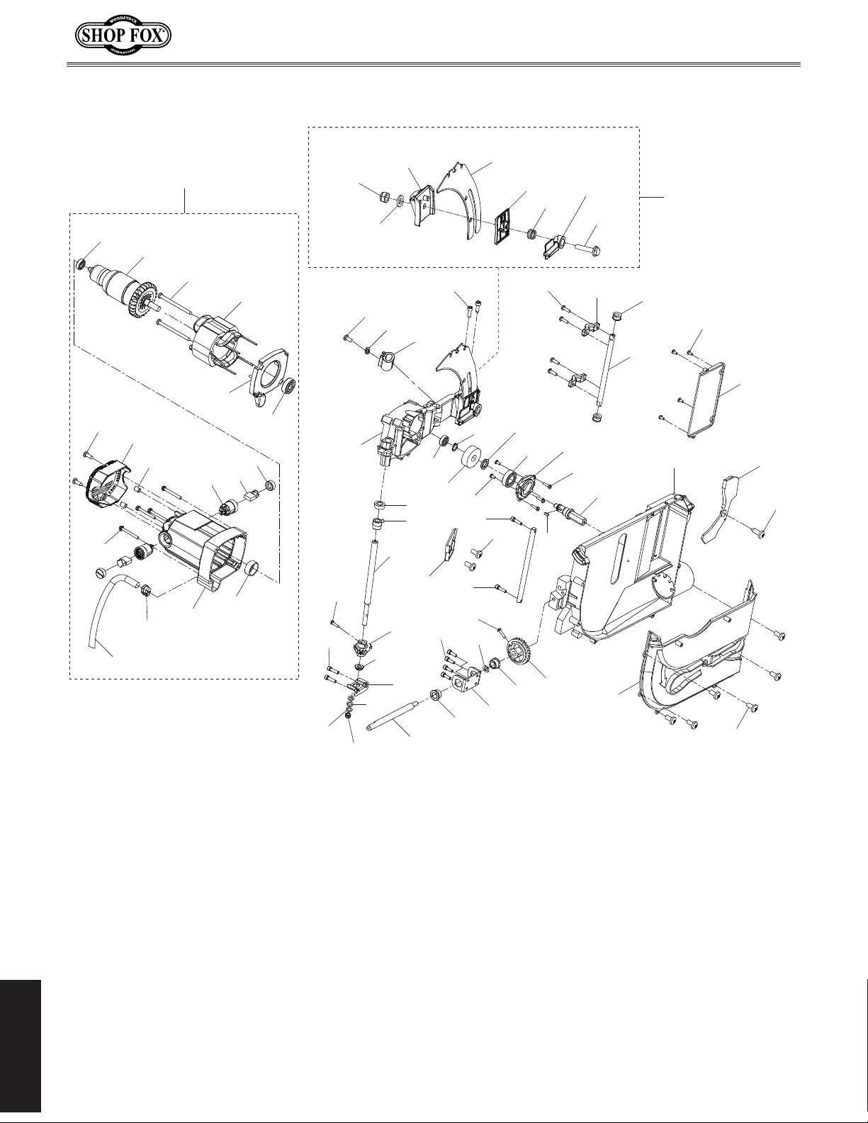
Model W1875 (For Machines Mfd. Since 1/20)
Motor & Gear Box
703
728
722
730
721
729
761
720
718
727
725
726
719
717
752-8
716
752-7
760
752-6
759
715
733
734
735
753
758
713
711
742
714
752-5
752-4
701
747
712
752-3
710
707
752-2
748
709
708
752-1
706
749
750
752
705
701
751
704
703
732
731
724
723
739
754
737
756
738
755
741
736
740
746
739
739
737
744
757
745
744
743
702
701
PARTS
-68-
Page 73
Model W1875 (For Machines Mfd. Since 1/20)
Motor & Gear Box Parts List
REF PART # DESCR IPTION R EF PART # DESCRIPTION
701 X18750701 PHLP HD SCR M4-.7 X 12 736 X18750736 BEVEL GEA R
702 X18750702 DUST COLLECTION COVER 737 X18750737 TAP SCREW M4 X 22
703 X18750703 TAP SCREW M4 X 12 738 X18750738 BUS H I NG
704 X18750704 LOW ER BLADE GUARD 739 X18750739 CAP SCREW M5-.8 X 20
705 X18750705 MOTOR BRACKET 740 X18750740 ELEVATION SHAFT PLATE
706 X18750706 ARBOR 741 X18750741 GUARD PLATE
707 X18750707 KEY 742 X18750742 ROD
708 X18750708 PHLP HD SCR M4-.7 X 16 743 X18750743 B EVEL GEAR
709 X18750709 GEAR BOX COVER 744 X18750744 DRIVE ROD BUSHING
710 X18750710 BALL BEARING 6003-2RS 745 X 18750745 DRIVE ROD BRACKET
711 X18750711 PHLP HD SCR M4-.7 X 10 746 X18750746 DRIVE ROD
712 X18750712 B USHING 747 X18750747 BUTTON HD CAP SCR M6-1 X 20
713 X18750713 GEAR 748 X18750748 ROD COLLAR
714 X18750714 EX T RET AINING RING 5MM 749 X18750749 ECCENTRI C SLEEVE
715 X18750715 BALL BEARING 608-2RS 750 X18750750 ROD
716 X18750716 GEAR BOX 751 X18750751 GEAR BOX GUARD PLATE
717 X18750717 BALL BEARING 6201-2RS 752 X 18750752 RIVING KNIFE ASSEMBLY
718 X18750718 FRONT MOTOR SHIELD 752-1 X18750752-1 FLANGE BOLT M6-1 X 30
719 X18750719 MOTOR STATOR 752-2 X18750752-2 LOCK LEVER
720 X18750720 TAP SCREW M5 X 60 752-3 X 18750752-3 TORSION SPRING
721 X18750721 MOTOR ARMATURE 752-4 X18750752-4 RIVING KNIFE CLAMP PLATE
722 X18750722 BALL BEARING 6000-2RS 752-5 X18750752-5 RIVING KNIFE/SPREADER
723 X18750723 BEAR ING SLEEVE 752-6 X18750752-6 RIVING KNIFE CLAMP BRACKET
724 X18750724 MOTOR HOUSING 752- 7 X18750752- 7 FENDER W ASH ER 6MM
725 X18750725 CARBON B RUSH END CAP 752-8 X18750752-8 LO CK NUT M6- 1
726 X18750726 CARBON BRUSH 753 X18750753 CAP SCREW M6-1 X 20
727 X18750727 CARBON BRUSH HOLDER 754 X18750754 FLAT WASHER 8MM
728 X18750728 PHLP HD SCR M5-.8 X 45 755 X18750755 FLAT WASHER 8MM
729 X18750729 SET SCREW M6-1 X 10 756 X 18750756 LOCK NUT M8-1.25
730 X18750730 REAR MOTOR SHIELD 757 X 18750757 W AVY WASHER 18MM
731 X18750731 STRAIN RELIEF TYP E-1 1/16 – 1/8 758 X18750758 SLEEVE
732 X18750732 MOTOR CORD 14G 2W 15" 759 X18750759 FENDER WASHER 5MM
733 X18750733 UPPER SHAFT COLLAR 760 X18750760 P HLP HD SCR M5-.8 X 25
734 X18750734 LOWER SHAFT COLLAR 761 X 18750761 MOTO R 2H P 120V 1-PH
735 X18750735 ELEVATION SHAFT
-69-
PARTS
Page 74
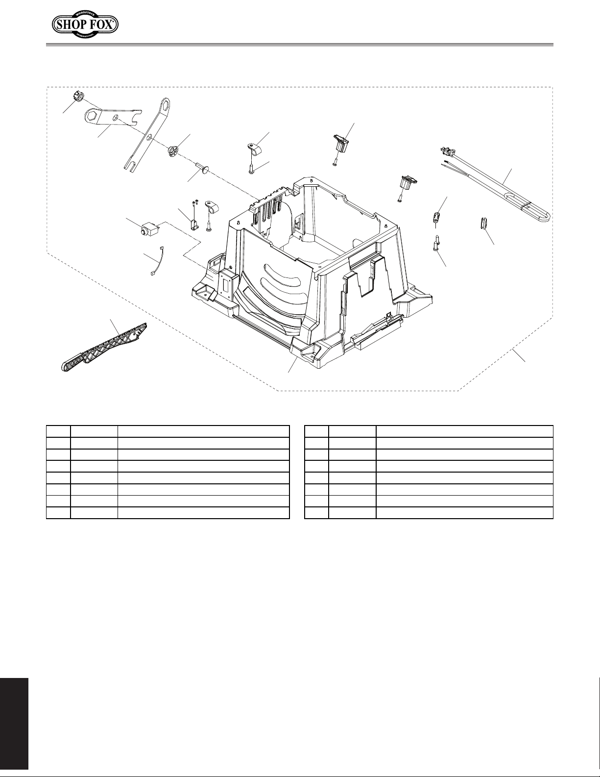
Base
807 X18750807 WIRE CLIP 815 X18750815 PUSH STICK
Model W1875 (For Machines Mfd. Since 1/20)
801
802
815
805
806
809
804
803
807
808
813
810
814
811
812
808
800
REF PA RT # DESCRIPTION REF PA RT # DESCRIPTION
800 X18750800 TABLE SAW BASE ASSEMBLY 808 X 18750808 TAP SCREW 4 X 16
801 X18750801 ROUND KNOB M8-1.25 809 X 18750809 ANTI-KICKBACK PAWLS STORAGE BRACKET
802 X18750802 ARBOR WRENCH 810 X18750810 CORD STORAGE BRACKET
803 X18750803 KNOB CLAMP M8-1.25 811 X18750811 CORD CLAMP
804 X18750804 CARRIAGE BOLT M6-1 X 28 812 X18750812 CORD SLEEVE
805 X18750805 CIRCUIT BREAKER 15A TS L2 S ERIES 813 X18750813 BASE
806 X18750806 CIRCUIT BREAKER WIRE 814 X 18750814 P OWER CORD 14G 2W 80" 5- 15P
PARTS
-70-
Page 75
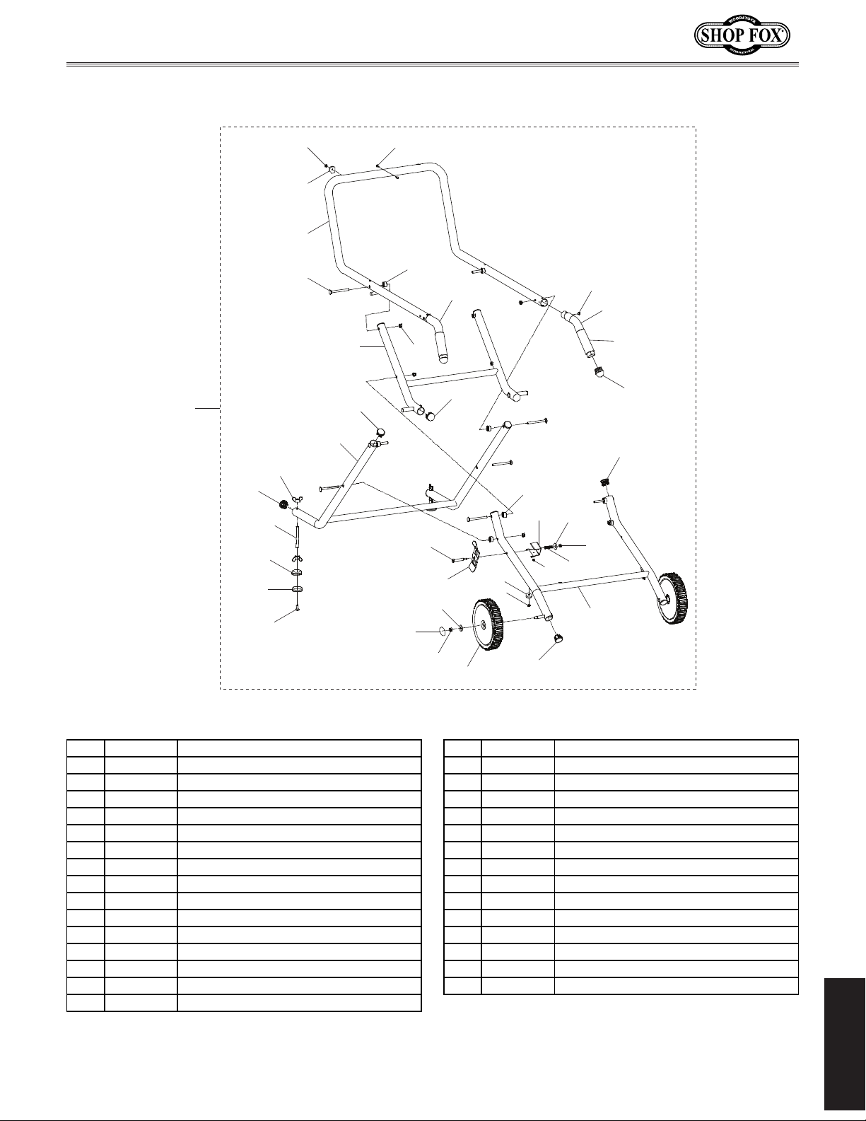
Model W1875 (For Machines Mfd. Since 1/20)
915 X18750915 PHLP HD SCR M4-. 7 X 12
Mobile Stand
900
909
914
912
913
915
911
902
904
905
901
910
908
909
903
923
906
907
916
924
917
930
909
902
901
918
919
901
901
927
928
929
909
921
922
920
926
907
925
909
REF PART # DESCRIPTION REF PART # DESCRIPTION
900 X18750900 MOBILE STAND ASSEMBLY 916 X18750916 SHO ULDER SCREW M6- 1 X 15, 8 X 43
901 X18750901 TAP SCREW M5 X 10 917 X18750917 STAND LOCK PLATE
902 X18750902 FOOT PAD 918 X18750918 STAND SPACER
903 X18750903 RIVET 5MM BLIND 919 X18750919 LOCK P LATE BRACKET
904 X18750904 UPPER STAND 920 X 18750920 COMPRESSION SPRING
905 X18750905 CARRIAGE BOLT M6-1 X 40 921 X18750921 FLAT WASHER 6MM
906 X18750906 STAND SPACER 922 X18750922 LOC K NUT M6- 1
907 X18750907 LOCK NUT M8-1.25 923 X18750923 END CAP
908 X18750908 MIDDLE STAND 924 X18750924 FENDER W ASH ER 8MM
909 X18750909 END CAP 925 X18750925 STAND W HEEL
910 X18750910 REAR STAND 926 X18750926 FRONT STAND
911 X18750911 WING NUT M10-1.5 927 X18750927 RIGHT HANDLE
912 X18750912 FOOT SH AFT 928 X18750928 GRIP
913 X18750913 FOOT 929 X 18750929 HANDLE END CAP
914 X18750914 FOOT COVER 930 X18750930 LEFT HANDLE
PARTS
-71-
Page 76
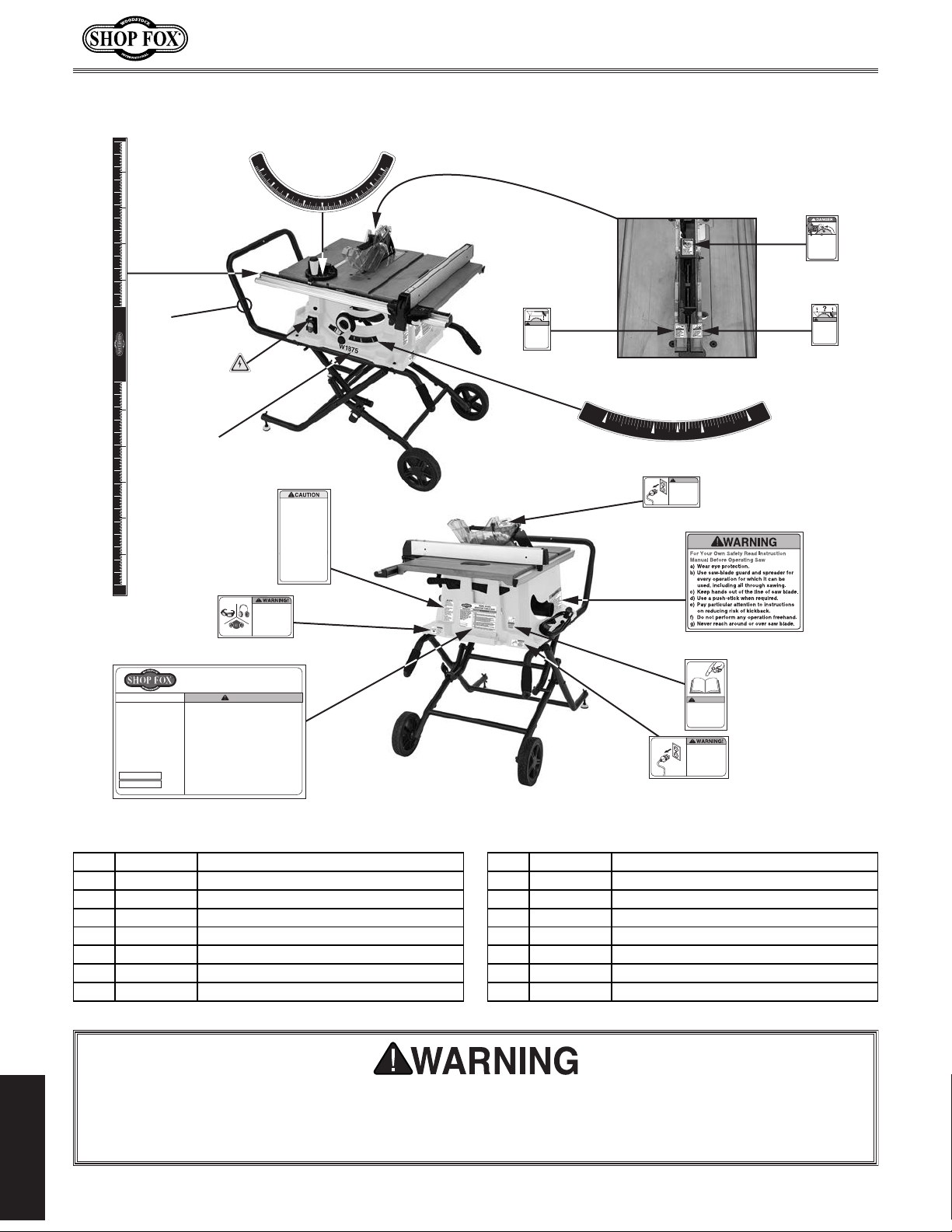
Model W1875 (For Machines Mfd. Since 1/20)
1001
1010
Labels & Cosmetics
12 11 10 9 8 7 6 5 4 3 2 1 0 12 13 14 1511109876543210
1016
1015
1014
W1875
1012
1011
MODEL W1875
Specifications
Motor: 2.5 HP, 120V, 1-Ph, 60 Hz
Full-Load Current Rating: 15A
Max Blade Size: 10" x 5/8" Arbor
Arbor Speed: 4400 RPM
Req. Blade Kerf: 0.094” - 0126”
Table Size: 23" x 35-1/8"
Max Rip Capacity: 31-1/8"
Max Depth of Cut @ 90°: 3-1/2"
Max Depth of Cut @ 45°: 2-1/2"
Max Dado Width: 13/16"
Weight: 70 lbs.
Mfd. for Woodstock in China
BENCHTOP TABLE SAW
WARNING!
To reduce risk of serious personal injury when using this
machine:
1. Read and understand owner’s manual before operating.
2. Never touch moving blade and keep hands out of cutting
path.
3. Always wear approved eye protection and respirator.
4. Only plug power cord into a grounded outlet.
5. Always use blade guard/spreader for all through cuts;
and use riving knife for all non-through cuts.
6. Only use blades meeting size/speed requirements of this
saw.
7. Never reach behind or over blade while it is moving.
8. Use a push stick when required and whenever possible.
9. Know what causes “kickback” and how to prevent it.
10. Do not perform any operation freehand.
Date
11. Disconnect power before changing blades or servicing
saw.
S/N
12. Prevent unauthorized use by children or untrained users;
restrict access or disable machine when unattended.
1002
60°
45°
INJURY HAZARD!
To reduce risk of shortand long-term injury,
wear safety glasses,
hearing protection, and
a respirator when using
this machine.
30°
15°
1013
The Model W1875
spreader/riving knife is
0.090" thick. Follow these
requirements to ensure the
spreader/riving knife works
safely:
BLADE REQUIREMENTS
Standard Blades
• Diameter: 10"
• Max. Body Thickness: 0.086"
• Min. Kerf Thickness: 0.094"
• Must be aligned with
spreader or riving knife.
Dado Blades
• Dado blades under 10"
diameter not compatible
with riving knife.
• Max Width: 13/16"
60°
45°
30°
15°
0°
1004
Removing
blade guard
increases risk
of injury—it
MUST be
installed when
possible.
1003
AMPUTATION
HAZARD!
Always keep
fingers and
hands away from
moving blade.
1005
WARNING!
If blade guard
is removed for
a special cut,
some other
safeguard
MUST be used.
1006
0°
15°
1007
22.5°
WARNING!
Disconnect
power before
changing blades
or blade guard
and riving knife.
30°
45°
1008
1009
WARNING!
READ and UNDERSTAND
MANUAL to avoid serious
injury! If a manual is not
available, DO NOT use
machine! Instead, go to
www.woodstockint.com
or call (360) 734-3482.
ACCIDENTAL INJURY
HAZARD!
Disconnect power
supply before
adjustments, setup
or maintenance!
REF PART # DESCRIPTION REF PART # DESCRIPTION
1001 X18751001 FENCE SCALE LAB EL 1009 X18751009 READ MANUAL LABEL
1002 X18751002 MI TER GAUGE SCALE LABEL 1010 X18751010 DISCONNECT 110V LABEL
1003 X18751003 AMPUTATION HAZARD LABEL 1011 X18751011 MACH INE ID LABEL
1004 X18751004 BLADE GUARD WARNING 1 LABEL 1012 X18751012 EYE EAR LUNG HAZ ARD LABEL
1005 X18751005 BLADE GUARD WARNING 2 LABEL 1013 X18751013 RIVING KNIFE LABEL
1006 X18751006 BLADE ANG LE LABEL 1014 X18751014 MO DEL NUMBER LABEL
1007 X18751007 DISCONNECT 110V BLADE G UAR D LABEL 1015 X18751015 ELECTR ICITY LABEL
1008 X18751008 TABLE SAW WARNING LABEL 1016 X18751016 TOUCH-UP PAINT, SHOP FOX BLACK
Safety labels warn about machine hazards and how to prevent serious personal injury. The owner
of this machine MUST maintain the original location and readability of all labels on this machine.
If any label is removed or becomes unreadable, REPLACE that label before allowing machine to
be operated again. Contact us at (360) 734-3482 or www.woodstockint.com to order new labels.
PARTS
-72-
Page 77

warranty does not apply to defects due directly or indirectly to misuse, abuse, negligence or accidents,
WARRANTY
WARRANTY
Woodstock International, Inc. warrants all Shop Fox machinery to be free of defects from workmanship
and materials for a period of two years from the date of original purchase by the original owner. This
lack of maintenance, or reimbursement of third party expenses incurred.
Woodstock International, Inc. will repair, replace, or arrange for a dealer refund, at its expense and
option, the Shop Fox machine or machine part proven to be defective for its designed and intended
use, provided that the original owner returns the product prepaid to an authorized warranty or repair
facility as designated by our Bellingham, Washington office with proof of their purchase of the product
within two years, and provides Woodstock International, Inc. reasonable opportunity to verify the
alleged defect through inspection. If it is determined there is no defect, or that the defect resulted
from causes not within the scope of Woodstock International Inc.'s warranty, then the original owner
must bear the cost of storing and returning the product.
This is Woodstock International, Inc.’s sole written warranty and any and all warranties that may be
implied by law, including any merchantability or fitness, for any particular purpose, are hereby limited
to the duration of this written warranty. We do not warrant that Shop Fox machinery complies with
the provisions of any law, acts or electrical codes. We do not reimburse for third party repairs. In no
event shall Woodstock International, Inc.’s liability under this limited warranty exceed the purchase
price paid for the product, and any legal actions brought against Woodstock International, Inc. shall be
tried in the State of Washington, County of Whatcom. We shall in no event be liable for death, injuries
to persons or property or for incidental, contingent, special or consequential damages arising from the
use of our products.
Every effort has been made to ensure that all Shop Fox machinery meets high quality and durability
standards. We are commited to continuously improving the quality of our products, and reserve the
right to change specifications at any time.
To register the warranty, go to https://www.woodstockint.com/warranty, or scan the QR code below.
You will be directed to the Warranty Registration page on www.woodstockint.com. Enter all applicable
production information.
WARRANTY
WOODSTOCKINT.COM
Page 78

 Loading...