

Page 1
READ THIS FIRST
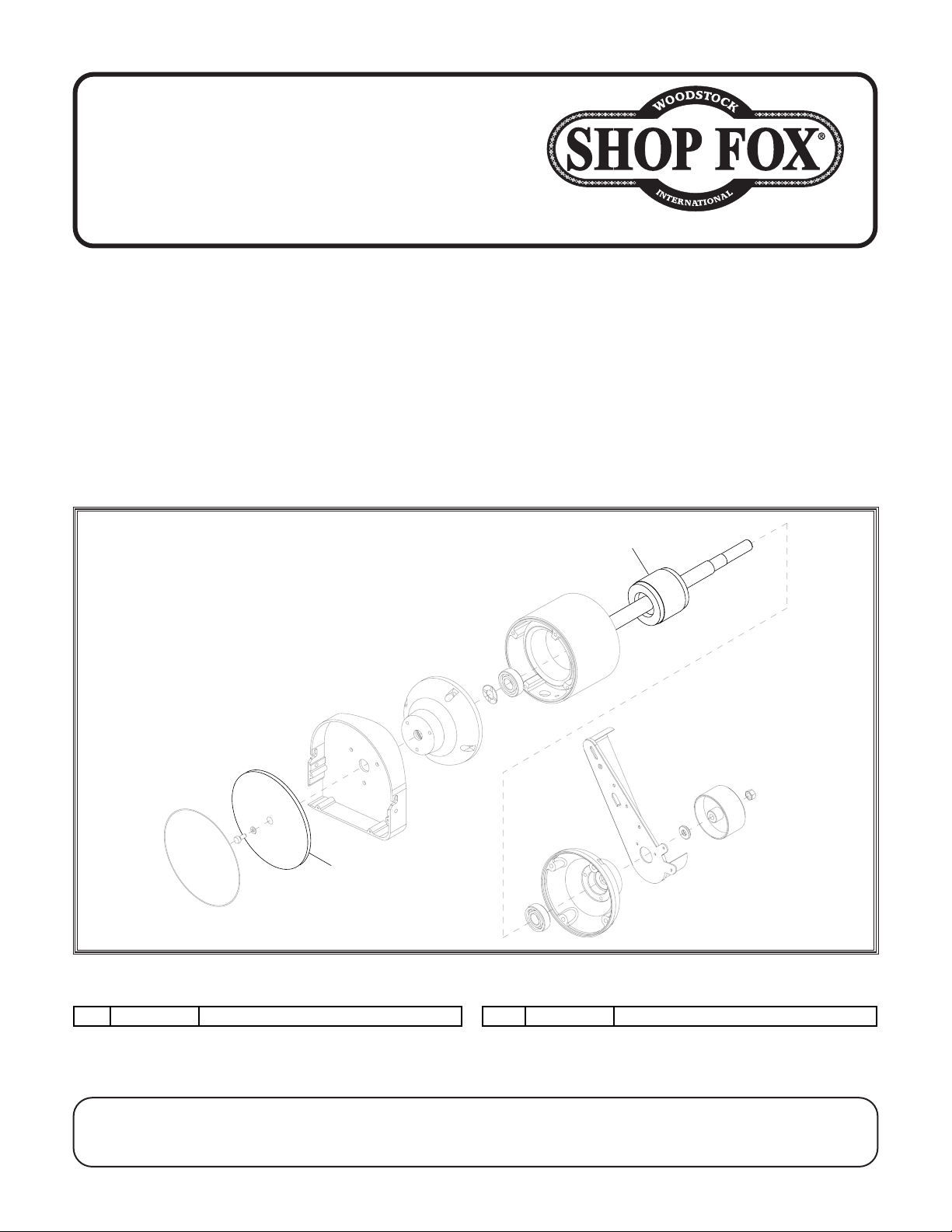
5V2 X1838005V2
SANDING DISC V2.10.23
26V2 X1838026V2
ROTOR V2.10.23
Model W1838
***IMPORTANT UPDATE***
Applies to Models Mfd. Since 10/23
and Owner's Manual Revised 08/18
Phone #: (360) 734-3482 • Tech Support: [email protected] • Web: www.woodstockint.com
The following changes were recently made since the owner's manual was printed:
• Sanding disc and rotor changed.
Aside from the information contained in this update, all other content in the owner's manual is
applicable and MUST be read and understood for your own safety.
IMPORTANT: Keep this update with the owner's manual for future reference. If you have any further
questions, contact our Technical Support.
Revised Parts
5V2
26V2
REF PAR T # DESCRIPTION REF PAR T # DESCRIPTION
COPYRIGHT © OCTOBER, 2023 BY WOODSTOCK INTERNATIONAL, INC.
WARNING: NO PORTION OF THIS MANUAL MAY BE REPRODUCED IN ANY SHAPE OR FORM WITHOUT
THE WRITTEN APPROVAL OF WOODSTOCK INTERNATIONAL, INC.
Printed in China#22503CS
Page 2
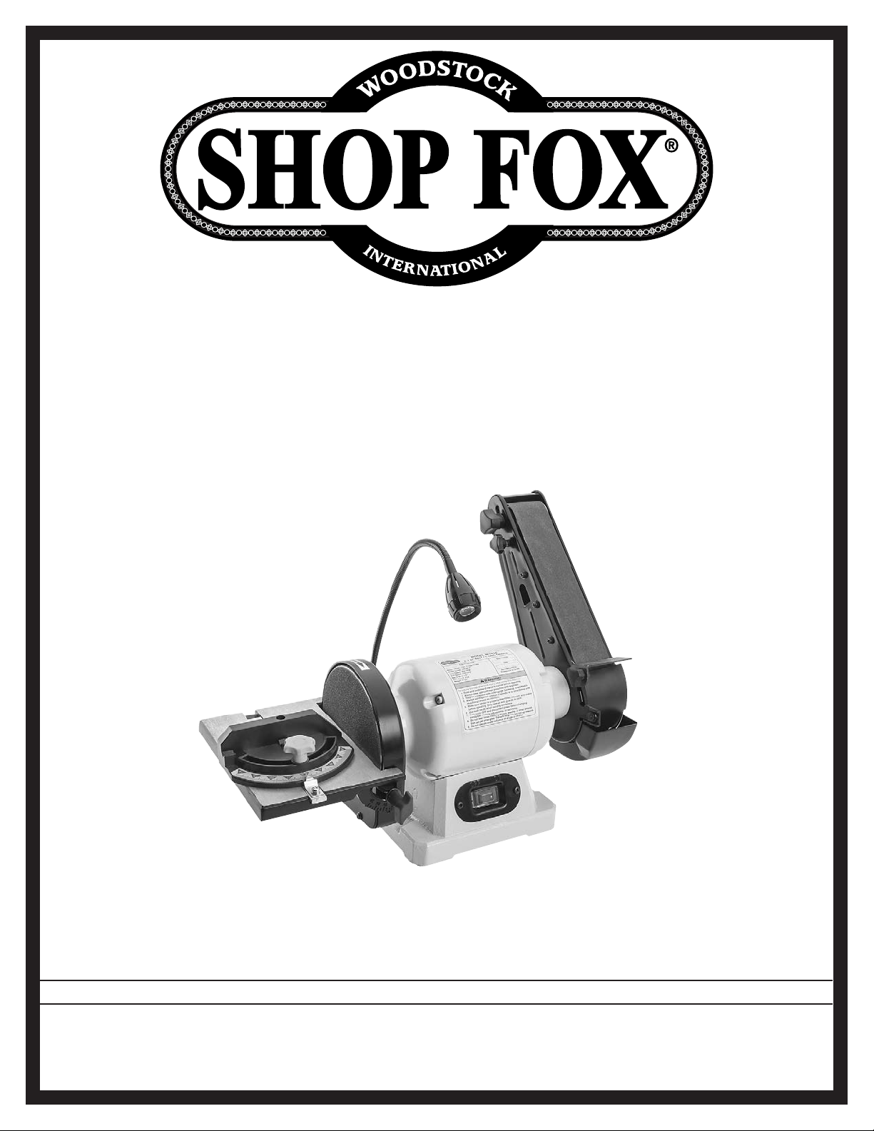
MODEL W1838
COMBO BENCHTOP
BELT/DISC SANDER
OWNER'S MANUAL
(FOR MODELS MANUFACTURED SINCE 6/16)
Phone: (360) 734-3482 • Online Technical Support: [email protected]
COPYRIGHT © JUNE, 2016 BY WOODSTOCK INTERNATIONAL, INC. REVISED AUGUST, 2018 (BL)
WARNING: NO PORTION OF THIS MANUAL MAY BE REPRODUCED IN ANY SHAPE OR FORM WITHOUT
THE WRITTEN APPROVAL OF WOODSTOCK INTERNATIONAL, INC.
#JH18160 Printed in China
Page 3
This manual provides critical safety instructions on the proper setup,
operation, maintenance, and service of this machine/tool. Save this
document, refer to it often, and use it to instruct other operators.
Failure to read, understand and follow the instructions in this manual
may result in fire or serious personal injury—including amputation,
electrocution, or death.
The owner of this machine/tool is solely responsible for its safe use.
This responsibility includes but is not limited to proper installation in
a safe environment, personnel training and usage authorization,
proper inspection and maintenance, manual availability and comprehension, application of safety devices, cutting/sanding/grinding tool
integrity, and the usage of personal protective equipment.
The manufacturer will not be held liable for injury or property
damage from negligence, improper training, machine modifications or
misuse.
Some dust created by power sanding, sawing, grinding, drilling, and
other construction activities contains chemicals known to the State of
California to cause cancer, birth defects or other reproductive harm.
Some examples of these chemicals are:
• Lead from lead-based paints.
• Crystalline silica from bricks, cement and other masonry products.
• Arsenic and chromium from chemically-treated lumber.
Your risk from these exposures varies, depending on how often you
do this type of work. To reduce your exposure to these chemicals:
Work in a well ventilated area, and work with approved safety equipment, such as those dust masks that are specially designed to filter
out microscopic particles.
Page 4

Table of Contents
INTRODUCTION .....................................2
Contact Info
Manual Accuracy
Machine Specifications
Identification
SAFETY ...............................................6
Standard Machinery Safety Instructions
Additional Safety for Combo Sanders
ELECTRICAL .........................................9
Circuit Requirements
Grounding Requirements
Extension Cords
SETUP .............................................. 11
Unpacking
Items Needed for Set Up
Inventory
Machine Placement
Cleaning Machine
Bench Mounting................................. 13
Assembly
Dust Collection
Test Run
OPERATIONS....................................... 16
General
Disc Sanding
Miter Sanding
Compound Angle Sanding
Belt Sanding
Adjusting Belt Tracking
Changing/Replacing
Sanding Disc
Changing/Replacing
Sanding Belt
....................................... 2
.................................. 2
.......................... 3
..................................... 5
...... 6
......... 8
............................ 9
...................... 10
................................ 10
....................................... 11
...................... 11
........................................ 11
............................ 12
............................... 12
......................................... 13
................................. 14
.......................................... 15
.......................................... 16
..................................... 17
................................... 18
..................... 18
..................................... 19
........................ 19
............................ 20
..................................... 20
............................ 21
..................................... 21
ACCESSORIES ...................................... 22
Combination Sander Accessories
MAINTENANCE .................................... 23
General
Cleaning & Protecting
Lubrication
SERVICE ............................................ 24
Troubleshooting
Calibrating Miter Gauge
Electrical Safety Instructions
Wiring Diagram
PARTS .............................................. 29
Main Parts Breakdown
WARRANTY ........................................ 33
.......................................... 23
......................... 23
...................................... 23
................................. 24
....................... 26
................................. 28
......................... 29
............. 22
................. 27
SAFETYINTRODUCTION
SET UPELECTRICAL MAINTENANCE
OPERATIONS
USE THE QUICK GUIDE PAGE LABELS TO SEARCH OUT INFORMATION FAST!
SERVICE PARTS
Page 5
INTRODUCTION
We are proud to provide a high-quality owner’s
manual with your new machine!
We
the
instructions, specifications, drawings, and photographs contained inside. Sometimes we make
mistakes, but our policy of continuous improvement
machine
you receive will be slightly different than what
is shown in the manual
If you find this to be the case, and the difference
between the manual and machine leaves you
confused about a procedure
check our website
for an updated version. W
manuals
and
on our website at
www.
Alternatively, you can call our Technical Support
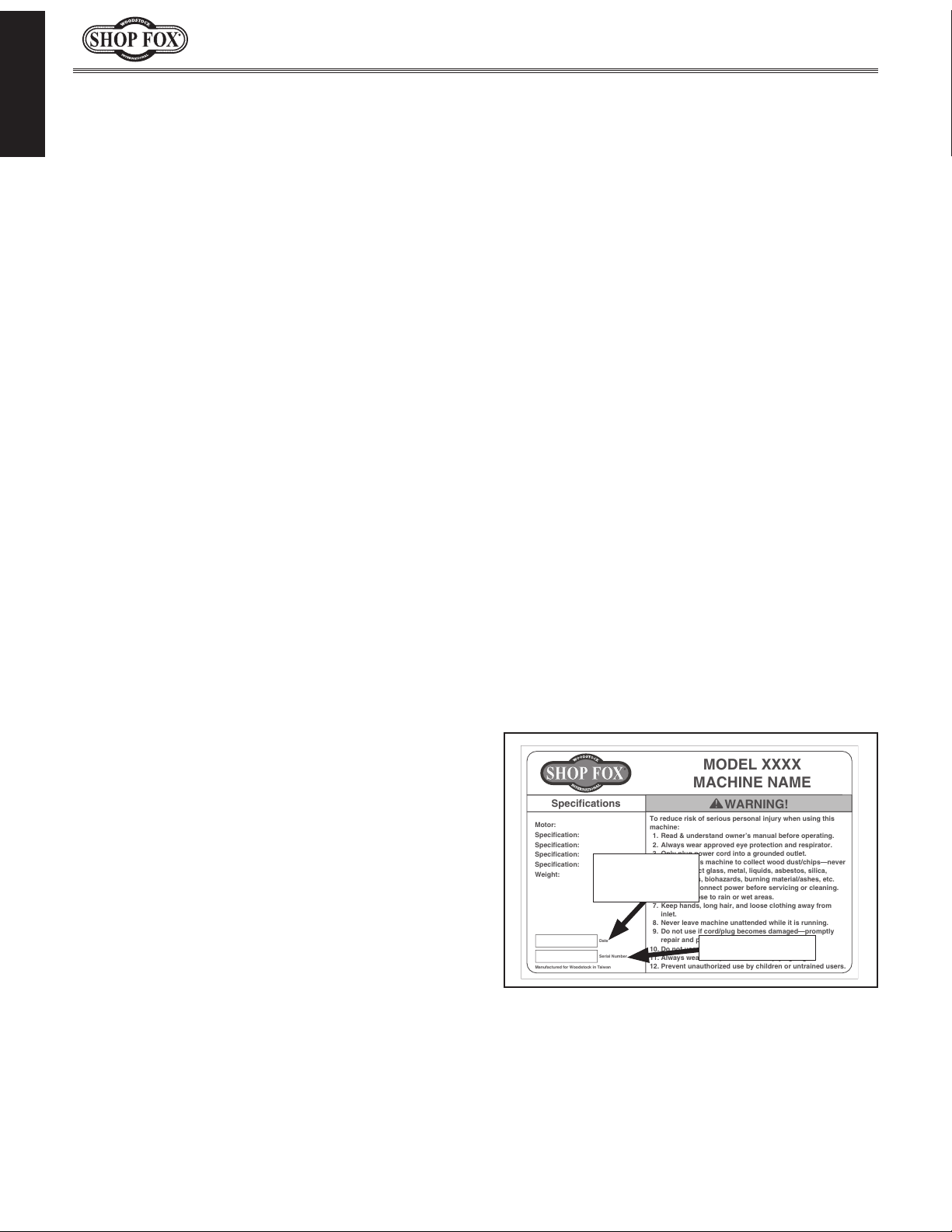
for help. Before calling, make sure you write
down the
from the machine ID label (see below). Also, if
available, have a copy of your original purchase
receipt on hand. This information is required for
all Tech Support calls.
MODEL XXXX
MACHINE NAME
Motor:
Specification:
Specification:
Specification:
Specification:
Weight:
Specifications
To reduce risk of serious personal injury when using this
machine:
1. Read & understand owner’s manual before operating.
2. Always wear approved eye protection and respirator.
3. Only plug power cord into a grounded outlet.
4. Only use this machine to collect wood dust/chips—never
use to collect glass, metal, liquids, asbestos, silica,
animal parts, biohazards, burning material/ashes, etc.
5. Always disconnect power before servicing or cleaning.
6. Do not expose to rain or wet areas.
7. Keep hands, long hair, and loose clothing away from
inlet.
8. Never leave machine unattended while it is running.
9. Do not use if cord/plug becomes damaged—promptly
repair and protect cord from future damage.
10. Do not use without dust bag or filters in place.
11. Always wear a respirator when emptying bags.
12. Prevent unauthorized use by children or untrained users.
Date
Serial Number
Manufactured for Woodstock in Taiwan
WARNING!
We are committed to customer satisfaction. If
you have any questions or need help, use the
information below to contact us.
IMPORTANT: Before contacting, please get the
original purchase receipt, serial number, and
manufacture date of your machine. This information is required for all Technical Support
calls and it will help us help you faster.
We want your feedback on this manual. What did
you like about it? Where could it be improved?
Please take a few minutes to give us feedback.
Email: [email protected]
Model W1838 (For Machines Mfd. Since 6/16)
INTRODUCTION
Contact Info
Woodstock International Technical Support
Phone: (360) 734-3482
Email: [email protected]
Technical Documentation Manager
P.O. Box 2309
Bellingham, WA 98227
Manual Accuracy
made every effort to be exact with
also means that sometimes the
.
,
e post current
manual updates for free
woodstockint.com.
Manufacture Date and Serial Number
Manufacture
Date
Serial Number
-2-
Page 6

Model W1838 (For Machines Mfd. Since 6/16)
MODEL W1838
COMBO BENCHTOP BELT/DISC SANDER
Product Dimensions
Weight........................................................................................................... 22 lbs.
Width (side‐to‐side) x Depth (front‐to‐back) x Height........................................ 20 x 19 x 12 in.
Footprint (Length x Width)............................................................................ 6‐1/2 x 4 in.
Shipping Dimensions
Type.................................................................................................... Cardboard Box
Content........................................................................................................ Machine
Weight........................................................................................................... 31 lbs.
Length x Width x Height........................................................................... 16 x 17 x 13 in.
INTRODUCTION
Electrical
Power Requirement.................................................................... 120V, Single‐Phase, 60 Hz
Prewired Voltage................................................................................................. 120V
Full‐Load Current Rating........................................................................................ 2.6A
Minimum Circuit Size............................................................................................. 15A
Connection Type......................................................................................... Cord & Plug
Power Cord Included.............................................................................................. Yes
Power Cord Length............................................................................................... 6 ft.
Power Cord Gauge............................................................................................ 18 AWG
Plug Included....................................................................................................... Yes
Included Plug Type............................................................................................... 5‐15
Switch Type............................................................................................ Rocker Switch
Motors
Main
Type......................................................................... TEFC Capacitor‐Start Induction
Horsepower.............................................................................................. 1/3 HP
Phase.............................................................................................. Single‐Phase
Amps......................................................................................................... 2.6A
Speed.................................................................................................. 3450 RPM
Power Transfer ................................................................................... Direct Drive
Bearings............................................................... Shielded & Permanently Lubricated
-3-
Page 7

INTRODUCTION
Model W1838 (For Machines Mfd. Since 6/16)
Main Specifications
Belt Sander Info
Sanding Belt Width........................................................................................ 2 in.
Sanding Belt Length...................................................................................... 27 in.
Sanding Belt Speed.................................................................................. 3550 FPM
Table Length.......................................................................................... 2‐3/4 in.
Table Width........................................................................................... 1‐1/8 in.
Table Thickness......................................................................................... 1/8 in.
Belt Tension Release Type............................................................................. Spring
Platen Type................................................................................................ Steel
Platen Length.............................................................................................. 5 in.
Platen Width............................................................................................... 2 in.
Disc Sander Info
Disc Diameter.............................................................................................. 6 in.
Disc Speed............................................................................................ 3450 RPM
Disc Sandpaper Backing Type............................................................................. PSA
Table Length............................................................................................... 8 in.
Table Width........................................................................................... 5‐1/4 in.
Table Thickness......................................................................................... 5/8 in.
Table Tilt................................................................................ Left 0, Right 45 deg.
Table‐to‐Floor Height..................................................................................... 6 in.
Construction Materials
Base.................................................................................................... Cast Iron
Table............................................................................................ Cast Aluminum
Frame.................................................................................................. Cast Iron
Disc.............................................................................................. Cast Aluminum
Miter Gauge.............................................................................................. Plastic
Paint Type/Finish........................................................................................ Epoxy
Other Related Info
Miter Gauge Slot Width................................................................................ 5/8 in.
Miter Gauge Slot Height............................................................................... 1/4 in.
Number of Dust Ports......................................................................................... 2
Dust Port Size......................................................................................... 1‐1/2 in.
Other
Country of Origin ............................................................................................... China
Warranty ....................................................................................................... 2 Years
Approximate Assembly & Setup Time ................................................................. 30 Minutes
Serial Number Location .................................................................................... ID Label
ISO 9001 Factory ................................................................................................... No
Certified by a Nationally Recognized Testing Laboratory (NRTL) .......................................... No
Features
Tool Rests
Rocker‐Type Switch
Flexible LED Work Light
Included 80‐Grit Sanding Belt
Included 80‐Grit Sanding Disc
Included Miter Gauge
-4-
Page 8
Model W1838 (For Machines Mfd. Since 6/16)
Identification
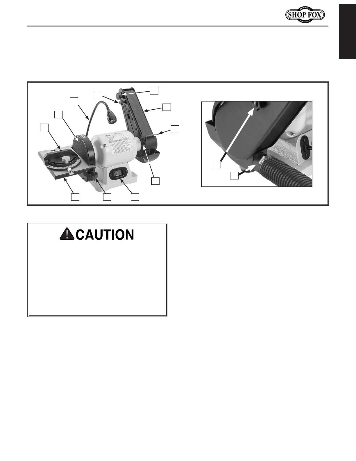
Refer to Figure 1 and the following descriptions to become familiar with the basic controls and
components of this machine. Understanding these items and how they work will help you understand the
rest of the manual and stay safe when operating this machine.
INTRODUCTION
D
C
B
A
K
J I
E
H
Figure 1. Identification.
For Your Own Safety Read Instruction
Manual Before Operating Sander.
a) Wear eye protection.
b) Support workpiece with miter gauge,
backstop, or work table.
c) Maintain 1⁄16" maximum clearance
between table and sanding disc or belt.
d) Avoid kickback by sanding in accordance
with directional arrows.
F
G
M
L
Tension Lock Knob: Tightens to secure belt
E.
tension. Loosens to release tension.
Note: Belt tension is controlled by a
spring. Lock knob only locks spring setting
in place.
F. Sanding Belt: Used for sanding with grain
along length of workpiece.
G. Backstop: Prevents workpiece from being
thrown by rotation of sanding belt.
A. Miter Gauge: Used for miter sanding.
Adjustable from 60° left to 60° right.
B. Sanding Disc: Interchangeable 6" abrasive
discs for performing angle, miter, and
square sanding operations.
C. LED Light: Adjusts to illuminate
workpieces. Turns ON and OFF by twisting
light head clockwise/counterclockwise.
Tracking Knob: Adjusts alignment of
D.
sanding belt on sanding bed.
H. Backstop Angle Knob: Tightens to secure
backstop at desired angle.
I. ON/OFF Switch: Turns motor ON and OFF.
J. Table Angle Knob: Adjusts angle of disc
sanding table.
. Disc Sanding Table: Supports workpiece
K
during disc sanding operation.
L. 1 1⁄2" Dust Port: Connects to dust collection
system (not included).
M. Side Guard Knob: Secures side guard.
-5-
Page 9

Model W1838 (For Machines Mfd. Since 6/16)
SAFETY
OWNER’S MANUAL.
TRAINED OPERATORS ONLY.
DANGEROUS ENVIRONMENTS.
MENTAL ALERTNESS REQUIRED.
electrical components or improperly grounded
manual uses a series of symbols and signal words intended to convey the level of importance of the
safety messages. The progression of symbols is described below. Remember that safety messages by
SAFETY
For Your Own Safety,
Read Manual Before Operating Machine
The purpose of safety symbols is to attract your attention to possible hazardous conditions. This
SAFETY
themselves do not eliminate danger and are not a substitute for proper accident prevention measures—this responsibility is ultimately up to the operator!
NOTICE
Standard Machinery Safety Instructions
Standard Machinery Safety Instructions
Indicates an imminently hazardous situation which, if not avoided,
WILL result in death or serious injury.
Indicates a potentially hazardous situation which, if not avoided,
COULD result in death or serious injury.
Indicates a potentially hazardous situation which, if not avoided,
MAY result in minor or moderate injury.
This symbol is used to alert the user to useful information about
proper operation of the equipment or a situation that may cause
damage to the machinery.
Read and understand this
owner’s manual BEFORE using machine.
have a higher risk of being hurt or killed. Only
allow trained/supervised people to use this
machine. When machine is not being used,
disconnect power, remove switch keys, or
lock-out machine to prevent unauthorized
use—especially around children. Make
workshop kid proof!
machinery in areas that are wet, cluttered,
or have poor lighting. Operating machinery
in these areas greatly increases the risk of
accidents and injury.
alertness is required for safe operation of
machinery. Never operate under the influence
of drugs or alcohol, when tired, or when
distracted.
Untrained operators
Do not use
Full mental
ELECTRICAL EQUIPMENT INJURY RISKS. You can
be shocked, burned, or killed by touching live
machinery. To reduce this risk, only allow an
electrician or qualified service personnel to
do electrical installation or repair work, and
always disconnect power before accessing or
exposing electrical equipment.
DISCONNECT POWER FIRST. Always disconnect
machine from power supply BEFORE making
adjustments, changing tooling, or servicing
machine. This eliminates the risk of injury
from unintended startup or contact with live
electrical components.
EYE PROTECTION. Always wear ANSI-approved
safety glasses or a face shield when operating
or observing machinery to reduce the risk of
eye injury or blindness from flying particles.
Everyday eyeglasses are not approved safety
glasses.
-6-
Page 10

Model W1838 (For Machines Mfd. Since 6/16)
WEARING PROPER APPAREL. Do not wear
HAZARDOUS
HEARING PROTECTION.
REMOVE ADJUSTING TOOLS.
INTENDED USAGE.
AWKWARD POSITIONS.
CHILDREN & BYSTANDERS.
GUARDS & COVERS.
FORCING MACHINERY. Do not force machine. It
will do the job safer and better at the rate for
loss of control. Before starting, verify machine
malfunction, leading to serious personal injury
from heated surfaces, high traffic areas, harsh
clothing, apparel, or jewelry that can become
entangled in moving parts. Always tie back
or cover long hair. Wear non-slip footwear to
avoid accidental slips, which could cause loss
of workpiece control.
DUST. Dust created while using
machinery may cause cancer, birth defects,
or long-term respiratory damage. Be aware of
dust hazards associated with each workpiece
material, and always wear a NIOSH-approved
respirator to reduce your risk.
Always wear hearing
protection when operating or observing
loud machinery. Extended exposure to this
noise without hearing protection can cause
permanent hearing loss.
machinery can become dangerous projectiles
upon startup. Never leave chuck keys,
wrenches, or any other tools on machine.
Always verify removal before starting!
intended purpose—never make modifications
without prior approval from Woodstock
International. Modifying machine or using
it differently than intended will void the
warranty and may result in malfunction or
mechanical failure that leads to serious
personal injury or death!
balance at all times when operating machine.
Do not overreach! Avoid awkward hand
positions that make workpiece control difficult
or increase the risk of accidental injury.
bystanders at a safe distance from the work
area. Stop using machine if they become a
distraction.
Only use machine for its
Tools left on
Keep proper footing and
Keep children and
which it was designed.
NEVER STAND ON MACHINE. Serious injury may
occur if machine is tipped or if the cutting
tool is unintentionally contacted.
STABLE MACHINE. Unexpected movement during
operation greatly increases risk of injury or
is stable and mobile base (if used) is locked.
USE RECOMMENDED ACCESSORIES. Consult
this owner’s manual or the manufacturer for
recommended accessories. Using improper
accessories will increase risk of serious injury.
UNATTENDED OPERATION. To reduce the risk
of accidental injury, turn machine OFF and
ensure all moving parts completely stop
before walking away. Never leave machine
running while unattended.
MAINTAIN WITH CARE. Follow all maintenance
instructions and lubrication schedules to
keep machine in good working condition. A
machine that is improperly maintained could
or death.
CHECK DAMAGED PARTS. Regularly inspect
machine for any condition that may affect
safe operation. Immediately repair or replace
damaged or mis-adjusted parts before
operating machine.
MAINTAIN POWER CORDS. When disconnecting
cord-connected machines from power, grab
and pull the plug—NOT the cord. Pulling the
cord may damage the wires inside, resulting
in a short. Do not handle cord/plug with wet
hands. Avoid cord damage by keeping it away
chemicals, and wet/damp locations.
SAFETY
accidental contact with moving parts or flying
debris—make sure they are properly installed,
undamaged, and working correctly.
Guards and covers reduce
EXPERIENCING DIFFICULTIES. If at any time
you experience difficulties performing the
intended operation, stop using the machine!
-7-
Contact Technical Support at (360) 734-3482.
Page 11

Model W1838 (For Machines Mfd. Since 6/16)
Additional Safety for Combo Sanders
Serious injury or death can occur if fingers, clothing, jewelry, or hair get entangled in moving
components. Impact injuries can occur from kickback if workpiece is improperly fed into moving
sandpaper. Serious pinch injuries can occur from touching in-running nip point between table and
SAFETY
sanding surface. Long-term respiratory damage can occur from using sander without proper use
of a respirator. To reduce the risk of these hazards, operator and bystanders MUST completely
heed the hazards and warnings below.
SANDPAPER DIRECTION. Feeding workpiece
incorrectly can cause it to be thrown from
machine, striking operator or bystanders, or
causing your hands to slip into the moving
sandpaper. To reduce these risks, only sand
against direction of sandpaper travel, ensure
workpiece is properly supported, and avoid
introducing sharp edges into moving sandpaper
on leading side of workpiece.
FEEDING WORKPIECE. Jamming workpiece into
sanding surface could cause it to be grabbed
aggressively, pulling hands into sanding surface. Firmly grasp workpiece in both hands
and ease it into sandpaper using light pressure.
AVOIDING ENTANGLEMENT. Entanglment in mov-
ing parts can cause pinching and crushing injuries. Keep all guards in place and closed. DO
NOT wear loose clothing, gloves, or jewelry,
and tie back long hair.
SANDING DUST. Sanding creates large amounts of
dust that can lead to eye injury or respiratory
illness. Reduce risk by wearing approved eye
and respiratory protection when using sander.
Never operate without adequate dust collection system in place and running. Dust collection is not a substitute for using a respirator.
WORKPIECE INTEGRITY. Sanding fragile work-
pieces can result in loss of control, resulting in
abrasion injuries, impact injuries, or damage
to sandpaper. Only sand solid workpieces that
can withstand power sanding forces. Make sure
workpiece shape is properly supported; avoid
sanding workpieces without flat bottom surfaces unless some type of jig is used to maintain support and control when sanding force is
applied.
SANDPAPER CONDITION. Worn or damaged sand-
paper can aggressively grab workpiece, resulting in subsequent injuries from operator loss
of workpiece control. Always inspect sandpaper before operation and replace if worn or
damaged.
WORKPIECE SUPPORT & HAND PLACEMENT.
Rotating sandpaper can remove a large
amount of flesh quickly, and kickback can
occur with violent force if workpiece is not
properly supported during operation. Always
sand with workpiece firmly against table or
another support device. Never touch moving
sandpaper on purpose.
IN-RUNNING NIP POINTS. The gap between mov-
ing sandpaper and fixed table/support creates a pinch point for fingers or workpieces;
the larger this gap is, the greater the risk of
fingers or workpieces getting caught in it.
Minimize this risk by adjusting table/support to
no more than
spindle sanders, always use the table insert
that fits closest diameter of installed drum.
MINIMUM STOCK DIMENSION. Small workpieces
can be aggressively pulled from your hands,
causing contact with sanding surface. Always
use a jig or other holding device when sanding
small workpieces, and keep hands and fingers
at least 2" away from sanding surface.
WORKPIECE INSPECTION. Nails, staples, knots,
or other imperfections in workpiece can be
dislodged and thrown from sander at a high
rate of speed at people, or cause damage to
sandpaper or sander. Never sand stock that
has embedded foreign objects or questionable
imperfections.
1
⁄16" away from sandpaper. For
-8-
Page 12
Model W1838 (For Machines Mfd. Since 6/16)
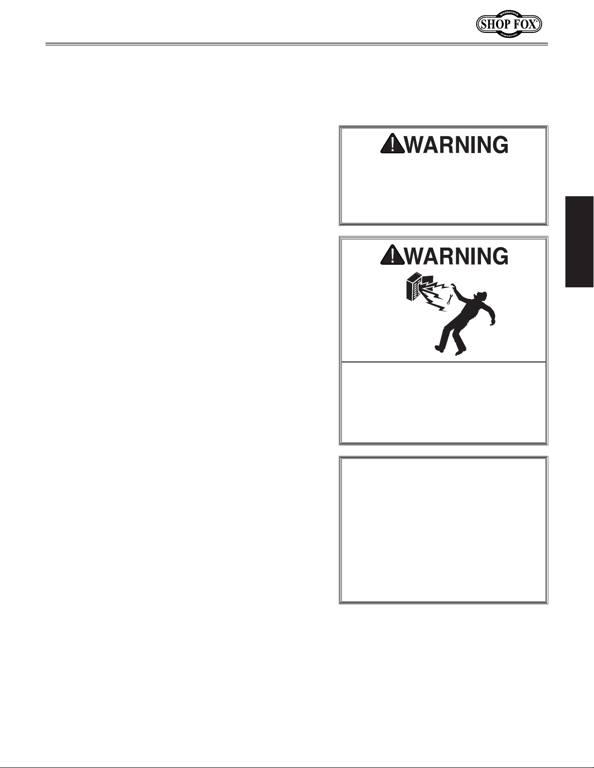
This machine must be connected to the correct size and
type of power supply circuit, or fire or electrical damage
may occur. Read through this section to determine if an
adequate power supply circuit is available. If a correct
circuit is not available, a qualified electrician MUST install
one before you can connect the machine to power.
A power supply circuit includes all electrical equipment
between the breaker box or fuse panel in the building
and the machine. The power supply circuit used for
this machine must be sized to safely handle the fullload current drawn from the machine for an extended
period of time. (If this machine is connected to a circuit
protected by fuses, use a time delay fuse marked D.)
This machine is prewired to operate on a power supply
circuit that has a verified ground and meets the following
requirements:
The full-load current rating is the amperage a machine
draws at 100% of the rated output power. On machines
with multiple motors, this is the amperage drawn by the
largest motor or sum of all motors and electrical devices
that might operate at one time during normal operations.
or machine damage. To reduce this risk,
a dedicated circuit—
where only one machine will be running
multiple machines will be running at the
ELECTRICAL
Circuit Requirements
The machine must be properly set up
before it is safe to operate. DO NOT
connect this machine to the power
source until instructed to do so later in
this manual.
ELECTRICAL
Full-Load Current Rating
Full-Load Current Rating at 120V ................. 2.6 Amps
Circuit Requirements for 120V
Circuit Type ...................... 120V, 60 Hz, Single-Phase
Circuit Size ............................................. 15 Amps
Plug/Receptacle .................................... NEMA 5-15
Incorrectly wiring or grounding this
machine can cause electrocution, fire,
only an electrician or qualified service
personnel should do any required
electrical work on this machine.
NOTICE
The circuit requirements listed in this
manual apply to
at a time. If this machine will be
connected to a shared circuit where
same time, consult with an electrician
to ensure that the circuit is properly
sized for safe operation.
-9-
Page 13
Grounding Requirements
This machine MUST be grounded. In the event of certain
types of
a path of least resistance for electric current
order
Improper connection of the equipment-grounding
will
increase
insulation
grounding
cord or plug is necessary, do not connect the equipmentgrounding
Check with a qualified electrician or service personnel
if
or if
properly grounded.
plug is damaged or worn, disconnect it from power, and
immediately replace it with a new one.
We do not recommend using an extension cord with
Any extension cord used with this machine must contain a
plug and receptacle, and
meet the following requirements:
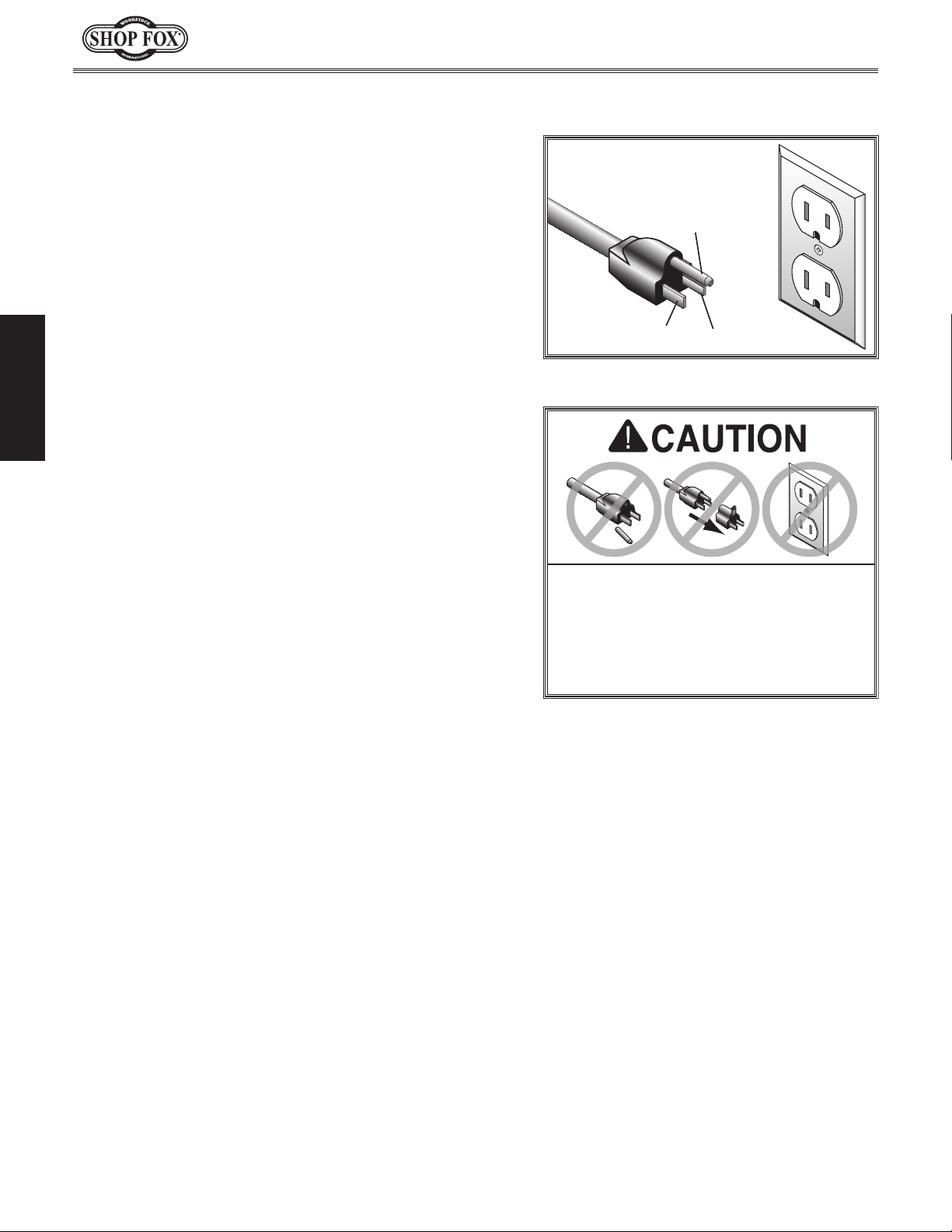
This machine is equipped with a power cord with an
equipment-grounding
plug
a matching
grounded in accordance with local codes and ordinances.
Model W1838 (For Machines Mfd. Since 6/16)
malfunctions or breakdowns, grounding provides
to reduce the risk of electric shock.
the risk of electric shock. The wire with green
(with/without yellow stripes) is the equipment-
wire. If repair or replacement of the power
wire to a live (current carrying) terminal.
you do not understand these grounding requirements,
you are in doubt about whether the tool is
ELECTRICAL
For 120V Connection
(see figure). The plug must only be inserted into
receptacle that is properly installed and
to travel—in
wire
If you ever notice that a cord or
wire and NE M A 5-15 grounding
120V
5-15 PLUG
Figure 2. NEMA 5-15 plug & receptacle.
DO NOT modify the provided plug or
use an adapter if the plug will not
fit the receptacle. Instead, have an
electrician install the proper receptacle
on a power supply circuit that meets
the requirements for this machine.
GROUNDED
5-15 RECEPTACLE
Grounding Prong
Neutral Hot
Extension Cords
this machine. Extension cords cause voltage drop, which
may damage electrical components and shorten motor
life. Voltage drop increases with longer extension cords
and smaller gauge sizes (higher gauge numbers indicate
smaller sizes).
ground wire, match the required
Minimum Gauge Size at 120V ...................... 14 AWG
Maximum Length (Shorter is Better) ................ 50 ft.
-10-
Page 14
Model W1838 (For Machines Mfd. Since 6/16)
This machine has been carefully packaged for safe
transportation. If you notice the machine has been
damaged during shipping, please contact your authorized
Shop Fox dealer immediately.
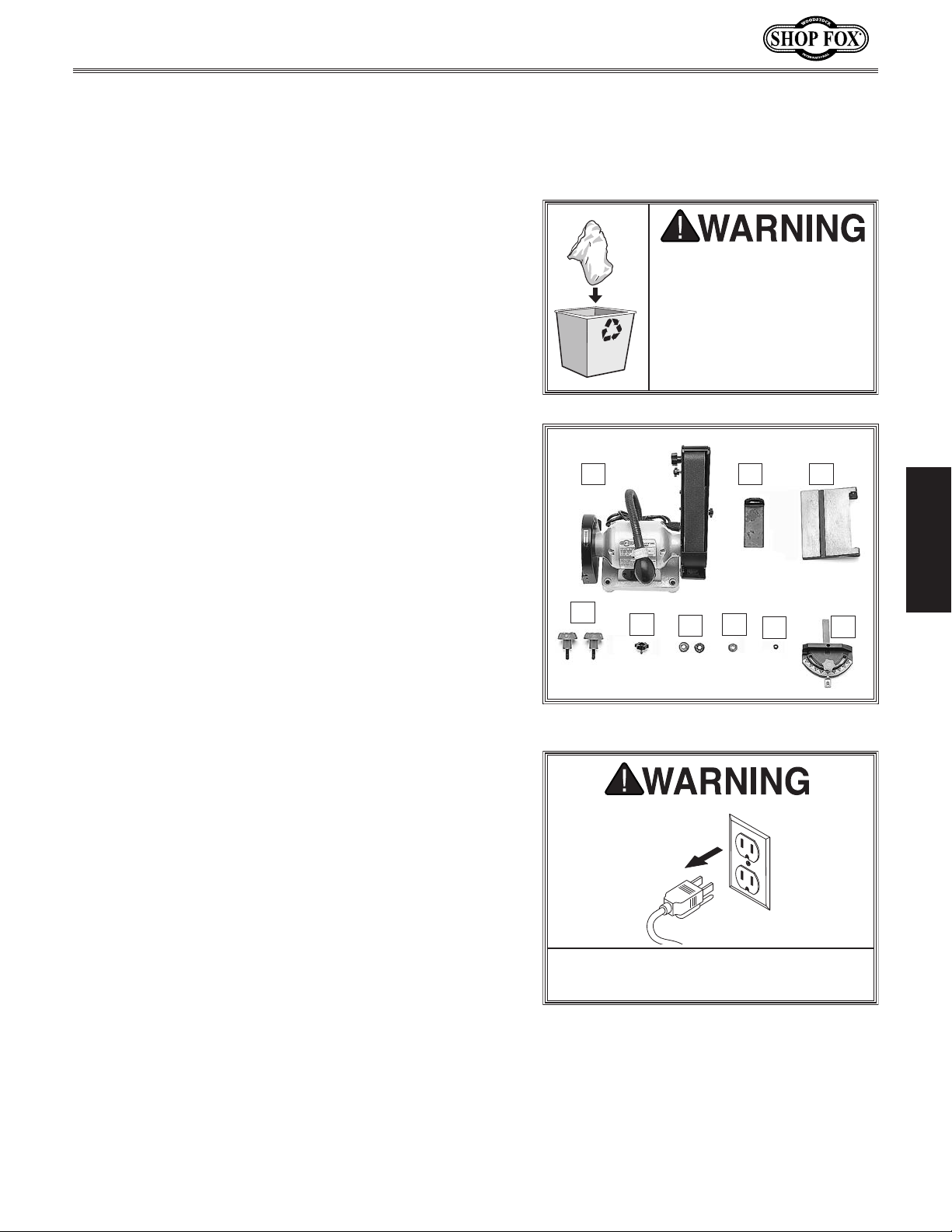
The following is a list of items shipped with your machine.
Before beginning setup, lay these items out and inventory
them.
Note:
check around/inside the machine and packaging materials.
Often, these items get lost in packaging materials while
unpacking or they are pre-installed at the factory.
Immediately discard all
materials to eliminate
SETUP
Unpacking
SUFFOCATION HAZARD!
plastic bags and packing
Items Needed for Set Up
The following items are needed to complete the set up
process, but are not included with your machine:
Description Qty
• Open-End Wrench 8mm ...................................1
• Open-End Wrench 13mm ..................................1
• Hex Bolt M8-1.25 (length varies) ........................2
• Flat Washers 8mm ..........................................4
• Lock Washers 8mm .........................................2
• Hex Nuts M8-1.25 ...........................................2
• 6" Machinist's Square .......................................1
Inventory
If you cannot find an item on this list, carefully
choking/suffocation
hazards for children and
animals.
A
B C
SETUP
D
E
Figure 3. Inventory.
G
F
H
I
Box Contents (Figure 3) Qty
A. Combo Sander ..............................................1
Backstop ....................................................1
B.
Disc Sanding Table .........................................1
C.
Sanding Table Lock Knobs M6-1 x 18 ...................2
D.
Backstop Angle Lock Knob M5-.8 x 10 ..................1
E.
Flat Washers 6mm (Sanding Table Lock Knobs) .......2
F.
Flat Washer 5mm (Backstop Angle Lock Knob) .......1
G.
Hex Nut M5-.8 (Backstop Angle Lock Knob) ...........1
H.
Miter Gauge ................................................1
I.
Keep machine disconnected from
power until instructed otherwise.
-11-
Page 15
Workbench Load
Refer to the Machine Specifications for the
weight and footprint specifications of your
machine. Some workbenches may require
additional reinforcement to support the weight
of the machine and workpiece materials.
Consider anticipated workpiece sizes and
additional space needed for auxiliary stands,
work tables, or other machinery when
establishing a location for this machine in the
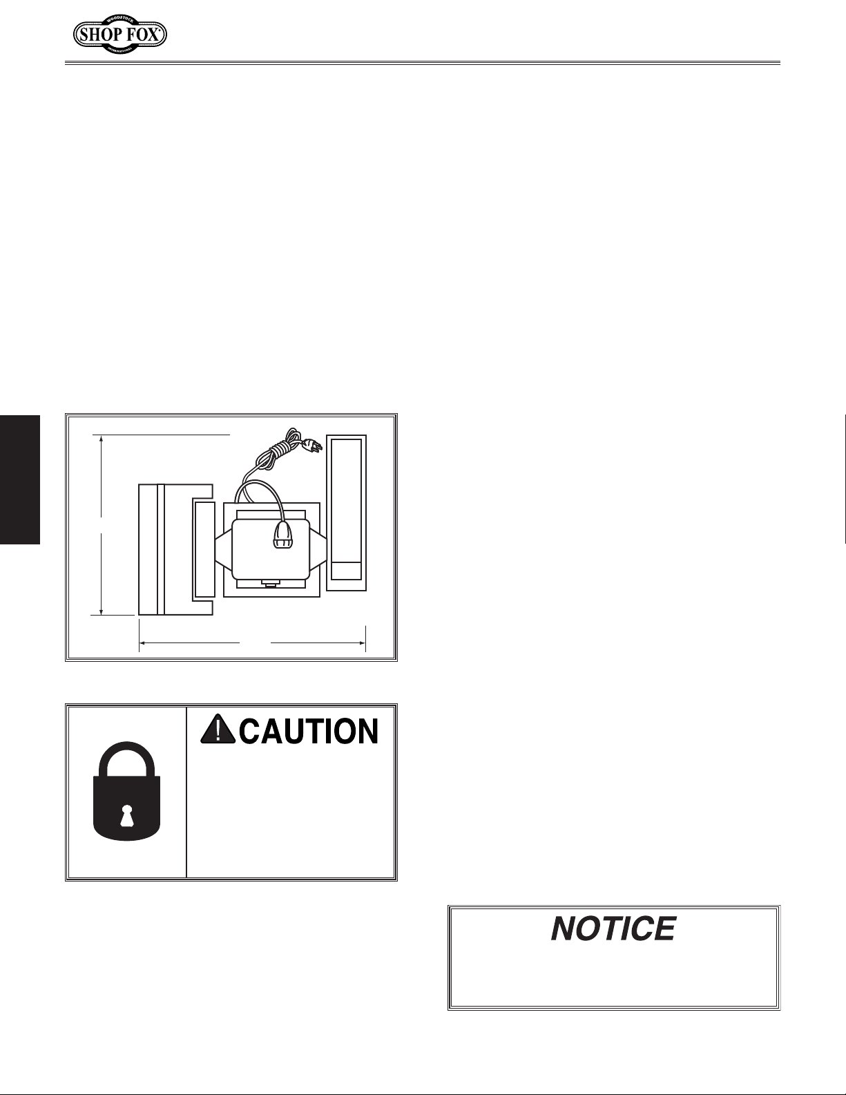
shop. Below is the minimum amount of space
needed for the machine.
users can injure themselves
The unpainted surfaces of your machine are
coated with a heavy-duty rust preventative that
prevents corrosion during shipment and storage.
This rust preventative works extremely well, but
it will take a little time to clean.
Be patient and do a thorough job cleaning your
machine. The time you spend doing this now will
give you a better appreciation for the proper
care of your machine's unpainted surfaces.
There are many ways to remove this rust
preventative, but the following steps work well
in a wide variety of situations. Always follow the
manufacturer’s instructions with any cleaning
product you use and make sure you work in a
well-ventilated area to minimize exposure to
toxic fumes.
Before cleaning, gather the following:
• Disposable rags
• Cleaner/degreaser (WD•40 works well)
• Safety glasses & disposable gloves
• Plastic paint scraper (optional)
Basic steps for removing rust preventative:
1.
2.
3.
4.
Placement Location
SETUP
19"
Model W1838 (For Machines Mfd. Since 6/16)
Cleaning MachineMachine Placement
20"
Figure 4. W1838 clearances.
INJURY HAZARD! Untrained
with this machine. Restrict
access to machine when
you are away, especially if
it is installed where children are present.
Put on safety glasses.
Coat the rust preventative with a liberal
amount of cleaner/degreaser, then let it
soak for 5–10 minutes.
Wipe off the surfaces. If your cleaner/
degreaser is effective, the rust
preventative will wipe off easily. If you
have a plastic paint scraper, scrape off as
much as you can first, then wipe off the
rest with the rag.
Repeat Steps 2–3 as necessary until clean,
then coat all unpainted surfaces with a
quality metal protectant to prevent rust.
Avoid chlorine-based solvents, such as
acetone or brake parts cleaner, that may
damage painted surfaces.
-12-
Page 16
Model W1838 (For Machines Mfd. Since 6/16)
The base of this machine has mounting holes that allow it
to be fastened to a workbench or other mounting surface
to prevent it from moving during operation and causing
accidental injury or damage.
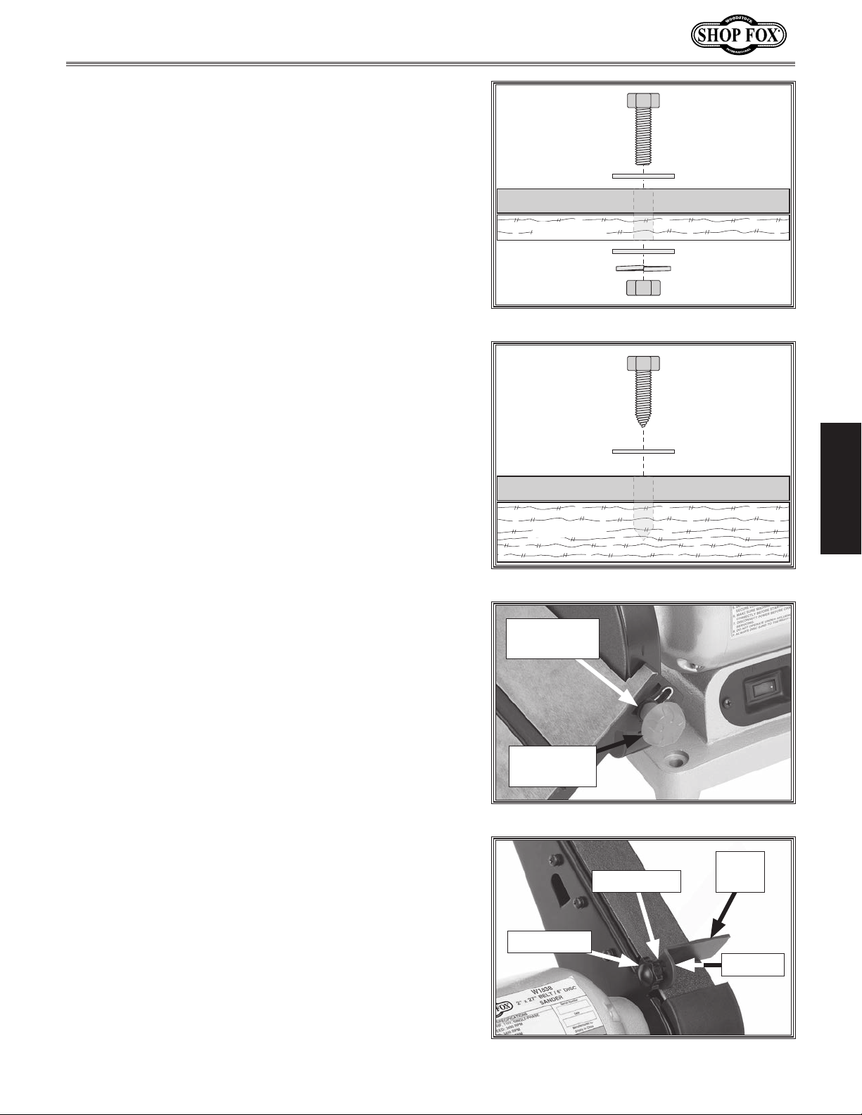
The strongest mounting option is a “Through Mount” (see
example) where holes are drilled all the way through the
workbench—and hex bolts, washers, and hex nuts are
used to secure the machine in place.
Another option is a “Direct Mount” (see example) where
the machine is secured directly to the workbench with lag
screws and washers.
Bench Mounting
Number of Mounting Holes .................................. 4
Diameter of Mounting Hardware Needed ..............1⁄2"
Bolt
Flat Washer
Machine Base
Workbench
Flat Washer
Lock Washer
Hex Nut
Figure 5. Typical "Through Mount" setup.
Lag Screw
Flat Washer
Machine Base
Workbench
SETUP
Assembly
The Model W1838 ships with the sanding belt and sanding
disc pre-installed.
To assemble machine, do these steps:
Attach disc sanding table with (2) M6-1 x 18 lock
1.
knobs and (2) 6mm flat washers (see Figure 7).
Set table to desired angle and tighten lock knobs.
2.
3. Attach backstop with (1) M5-.8 x 10 lock knob, (1)
5mm washer, and (1) M5-.8 hex nut, as shown in
Figure 8.
Use a square to position backstop perpendicular to
4.
sanding belt, as shown in Figure 8, with approximately
knob to secure setting.
1
⁄8" between backstop and belt. Tighten angle
Figure 6. Typical "Direct Mount" setup.
Flat Washer
(1 of 2)
Lock Knob
(1 of 2)
Figure 7. Installing disc table.
Back
Flat Washer
Angle Knob
Stop
Hex Nut
Figure 8. Squaring the backstop.
-13-
Page 17
Dust Collection
Do not confuse this CFM recommendation with the rating
of the dust collector. To determine the CFM at the dust
port, you must consider these variables: (1) CFM rating of
the dust collector, (2) hose type and length between the
dust collector and the machine, (3) number of branches
or wyes, and (4) amount of other open lines throughout
the system. Explaining how to calculate these variables
is beyond the scope of this manual. Consult an expert or
purchase a good dust collection “how-to” book.
Recommended CFM at Dust Port ................. 150 CFM
Model W1838 (For Machines Mfd. Since 6/16)
Dust Port
This machine creates substantial amounts of dust
during operation. Breathing airborne dust on a regular basis can result in permanent respiratory illness.
Reduce your risk by wearing a respirator and capturing the dust with a dust collection system.
SETUP
The dust ports are located behind both the sanding belt
and the sanding disc. Each opening is 1
and can be connected to a utility vacuum or a dust
colle cto r.
Tools Needed Qty
Dust Collection System
Dust Hose 1
Hose Clamps 4"
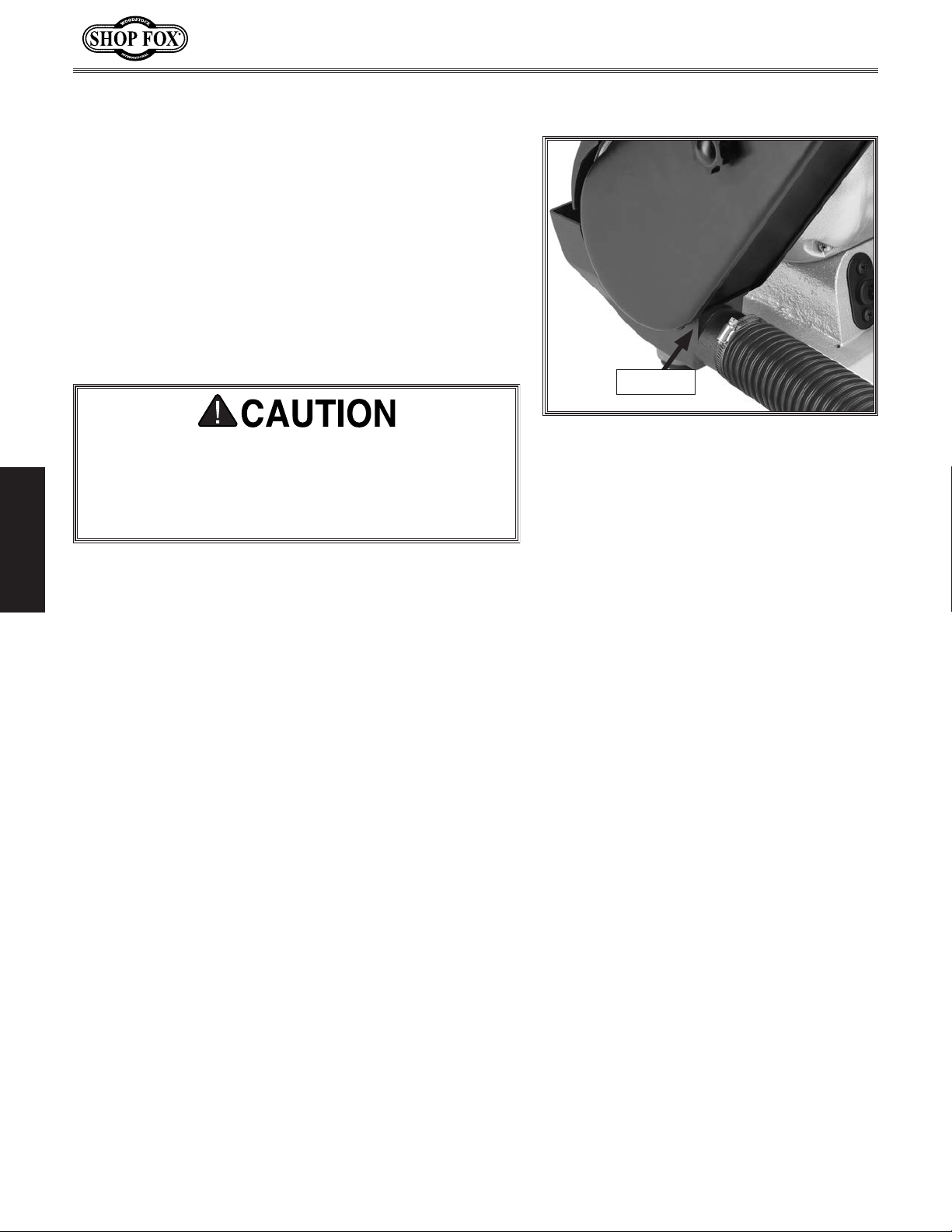
To connect a dust collection hose, do these steps:
1. Fit 21⁄2" dust hose over dust port, as shown in Figure
9, and secure in place with hose clamp.
1
⁄2" ..................................................1
..................................................2
........................................1
1
⁄2" in diameter
Figure 9. Dust port with dust collection
hose installed.
Tug hose to make sure it does not come off.
2.
Note: A tight fit is necessary for proper
performance.
-14-
Page 18
Model W1838 (For Machines Mfd. Since 6/16)
performed. Operating an improperly set
Once assembly is complete, test run the machine to
ensure it is properly connected to power and safety
components are functioning properly.
If you find an unusual problem during the test run,
immediately stop the machine, disconnect it from power,
and fix the problem BEFORE operating the machine again.
The
section of this
manual can help.
Test Run
Troubleshooting table in the SERVICE
Belt tracking will need to be adjusted during the test run
and every time the belt is changed. While conducting test
run and belt tracking, verify motor is running smoothly
and with out unusual noise.
Serious injury or death can result
from using this machine BEFORE
understanding its controls and related
safety information. DO NOT operate, or
allow others to operate, machine until
the information is understood.
DO NOT start machine until all
preceding setup instructions have been
To test run machine, do these steps:
1. Clear all setup tools away from machine.
2. Connect machine to power supply.
3. Turn machine ON, verify motor operation, and then
turn machine OFF.
The motor should run smoothly and without unusual
noises.
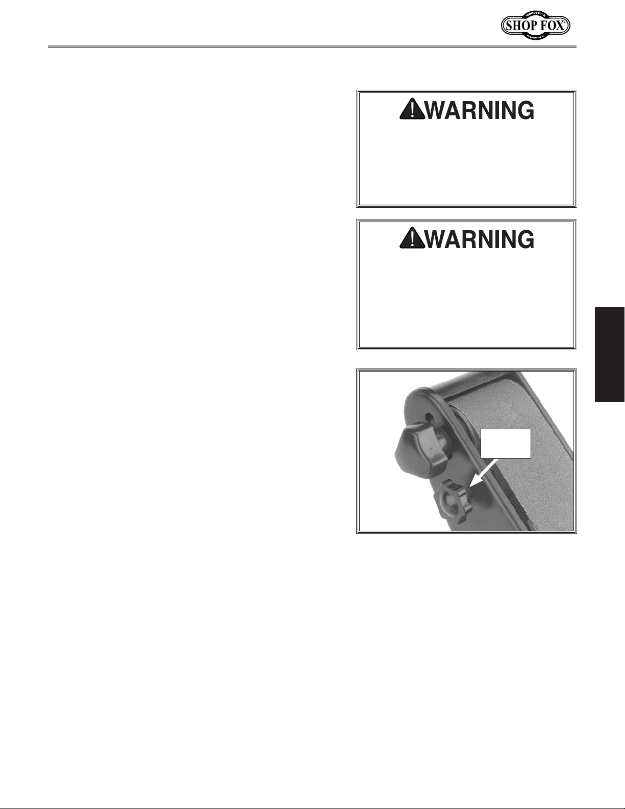
—If sanding belt moves toward disc, rotate tracking
knob counterclockwise (see Figure 10)
—If sanding belt moves away from disc, rotate track-
ing knob clockwise
Repeat the same process from Step 3 until the
4.
sander tracks properly and can be left running.
1
⁄2 turn.
1⁄2 turn.
up machine may result in malfunction
or unexpected results that can lead
to serious injury, death, or machine/
property damage.
Tracking
Knob
Figure 10. Sanding belt tracking knob.
SETUP
-15-
Page 19
OPERATIONS
This machine will perform many types of operations
that are beyond the scope of this manual. Many of these
operations can be dangerous or deadly if performed
incorrectly.
The instructions in this section are written with the
understanding that the operator has the necessary
knowledge and skills to operate this machine. If at any
time you are experiencing difficulties performing any
operation, stop using the machine!
The overview below provides the novice machine operator
with a basic understanding of how the machine is used
during operation, so the machine controls/components
discussed later in this manual are easier to understand.
Due to its generic nature, this overview is
to be an instructional guide.
General
Model W1838 (For Machines Mfd. Since 6/16)
To reduce your risk of serious injury
or damage to the machine, read this
entire manual BEFORE using machine.
NOT intended
To complete a typical operation, the operator does the
following:
Examines workpiece to make sure it is suitable for
1.
sanding.
Adjusts table tilt, if necessary, to correct angle for
2.
operation.
OPERATIONS
Makes sure sandpaper is in good condition and
3.
properly mounted.
Puts on safety glasses and a respirator, and turns
4.
dust collection system ON.
Starts sander.
5.
6. Makes sure sanding belt is tracking properly.
7. Feeds workpiece slowly into sandpaper while
maintaining firm pressure on workpiece against
table, miter gauge, or backstop. Keeps hands and
fingers away from moving sandpaper.
Stops the machine.
8.
To reduce the risk of eye injury and
long-term respiratory damage, always
wear safety glasses and a respirator
while operating this machine.
If you are an inexperienced operator,
we strongly recommend that you read
books or trade articles, or seek training
from an experienced operator of this
type of machinery before performing
unfamiliar operations. Above all, safety
must come first!
-16-
Page 20
Model W1838 (For Machines Mfd. Since 6/16)
Disc Sanding
Setting Table Tilt
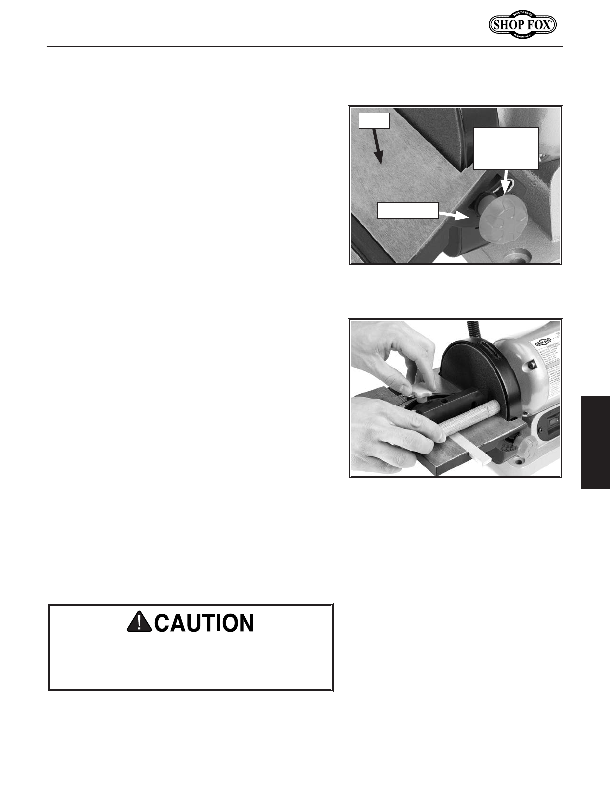
To set the work table angle relative to the sanding disc,
use the angle scale on the sander body, or for greater
accuracy, a protractor or machinist's square can be used.
To set table tilt, do these steps:
1. DISCONNECT MACHINE FROM POWER!
Table
Angle
Adjustment
Knob
2. Loosen angle adjustment knob, and position work
table so pointer aligns with desired angle on table
tilt scale (see
— For greater accuracy, use a protractor or machinist's
square.
Figure 11).
Performing Disc Sanding Operations
It helps to brace your workpiece against the miter gauge
for maximum stability when sanding straight edges or
specific angles.
To perform disc sanding operations, do these steps:
Set table tilt and miter gauge angles.
1.
Turn machine ON.
2.
Place workpiece on table and brace it against miter
3.
gauge (see
While keeping workpiece snug against miter gauge
4.
fence, gently feed it into downward spinning half of
sanding disc (see
Figure 12).
Figure 12).
Angle Scale
Figure 11. Table adjustment knob and
scale.
OPERATIONS
Figure 12. Disc sanding using a miter
gauge.
Use light pressure and slowly move workpiece back
5.
and forth along downward spinning half of sanding
disc. Keep workpiece moving to prevent burning
workpiece and excessive loading of sandpaper.
Only sand workpiece on side of sanding disc that
is rotating down toward work table. This will keep
workpiece from flying out of your hands from
rotational force of disc.
-17-
Page 21
Miter Sanding
The most efficient way to get a perfect miter is to cut
the workpiece long and sand it to the desired dimension.
To perform miter sanding operations, do these steps:
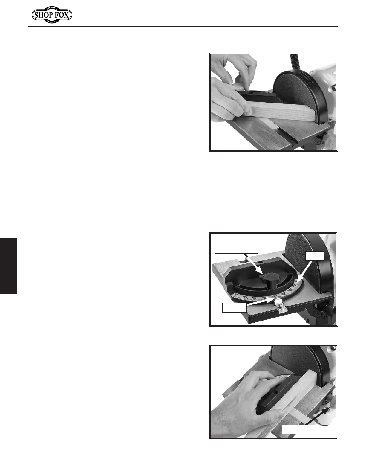
Loosen the knob on the miter gauge, adjust the
1.
angle to the desired point, and tighten the knob.
Note: For 90° horizontal sanding, set miter gauge to 0°.
Slide the miter gauge into its slot and use it to hold
2.
your workpiece in position.
Model W1838 (For Machines Mfd. Since 6/16)
Note: The miter gauge can be used in either
direction in the slot to achieve the proper relation
of the workpiece to the disc.
Using light pressure, move the workpiece slowly back
3.
and forth across the disc, as shown in Figure 13.
Compound Angle Sanding
Compound angles can be sanded with the table tilted and
the miter gauge angled off of 90°.
To perform angle sanding operations, do these steps:
Set table tilt to desired angle (see Figure 15).
1.
OPERATIONS
Note: The table can be positioned from 0˚ to 45˚,
relative to the sanding disc.
Set angle of miter gauge.
2.
3. Slide miter gauge into miter slot and use miter
gauge to hold workpiece in position.
Figure 13. Disc sanding with a miter
gauge.
Miter Gauge
Lock Knob
Scale
Pointer
Figure 14. Miter gauge adjustments.
Using light pressure, move workpiece slowly back
4.
and forth across the disc, as shown in Figure 15).
Angle Knob
Figure 15. Mitering with the table angled.
-18-
Page 22
Model W1838 (For Machines Mfd. Since 6/16)
Belt Sanding
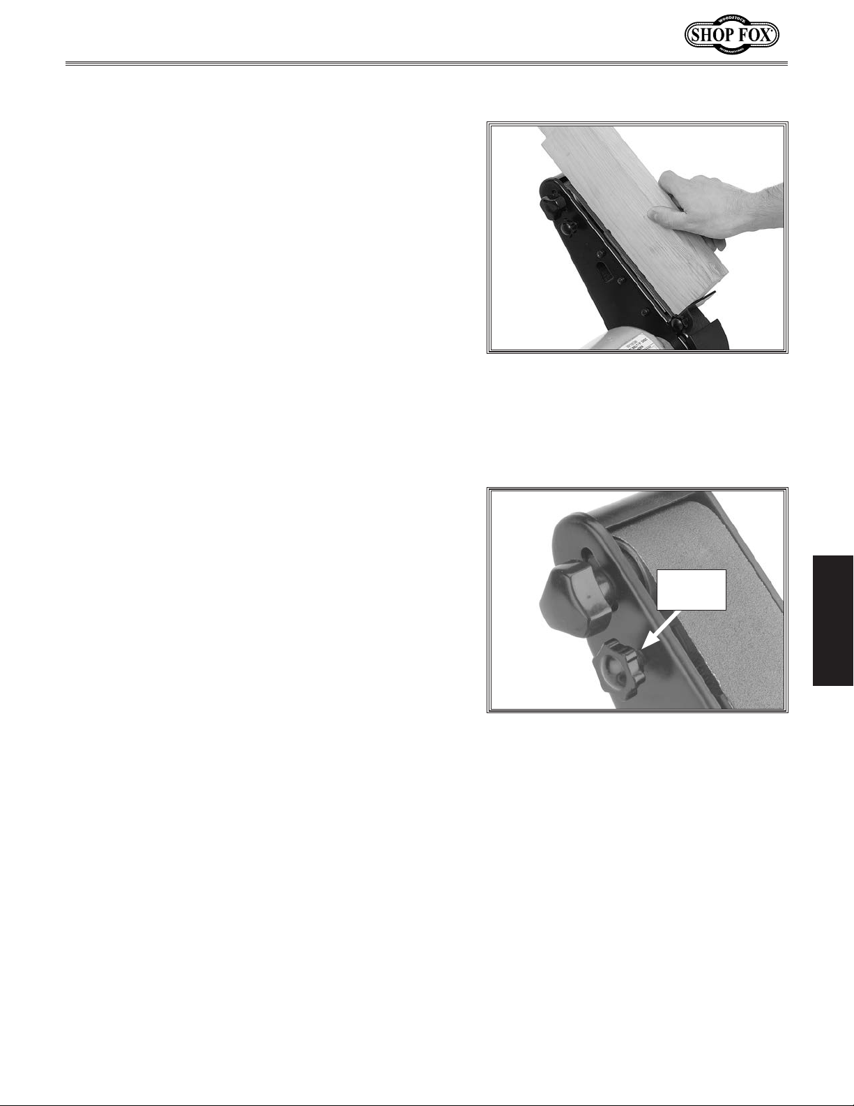
Belt sanding allows you to sand with the grain along the
length of the workpiece.
To perform belt sanding operations, do these steps:
Turn power ON and allow sander to reach full speed.
1.
Place workpiece against surface of sanding belt,
2.
using the backstop to prevent workpiece from being
thrown off by rotation of sanding belt while holding
workpiece firmly, as shown in Figure 16.
Move workpiece across surface of belt for even belt
4.
wear.
Figure 16. Belt sanding.
Adjusting Belt Tracking
Belt tracking will need to be adjusted every time the belt
is changed. A properly adjusted belt helps maximize belt
life and minimizes edge fraying.
To test belt tracking, do these steps:
1. Remove all tools and objects from sander, and then
connect sander to power. Turn sander ON and then
immediately OFF.
—If sanding belt moves toward disc, rotate tracking
knob counterclockwise (see Figure 17
—If sanding belt moves away from disc, rotate track-
ing knob clockwise
Repeat the same process from Step 2 until the
2.
sander tracks properly and can be left running.
1
⁄2 turn.
) 1⁄2 turn.
OPERATIONS
Tracking
Knob
Figure 17. Sanding belt tracking knob.
-19-
Page 23
Changing/Replacing
Sanding Disc
The Model W1838 Combo Sander accepts 6" diameter cloth
or paper-backed pressure sensitive adhesive (PSA) sanding
discs. These are available in the current Shop Fox catalog
in a variety of grits.
The PSA sanding disc sticks directly to the surface of the
aluminum disc and can be replaced with little effort.
Often if the disc is still warm from sanding, the adhesive
will be soft enough that the disc will come off very easily.
Model W1838 (For Machines Mfd. Since 6/16)
x 2
Components and Hardware Needed: Qty
6" PSA disc sandpaper ..........................................1
Screwdriver #2 Phillips
To change/replace sanding disc, do these steps:
DISCONNECT MACHINE FROM POWER!
1.
Remove sanding disc table.
2.
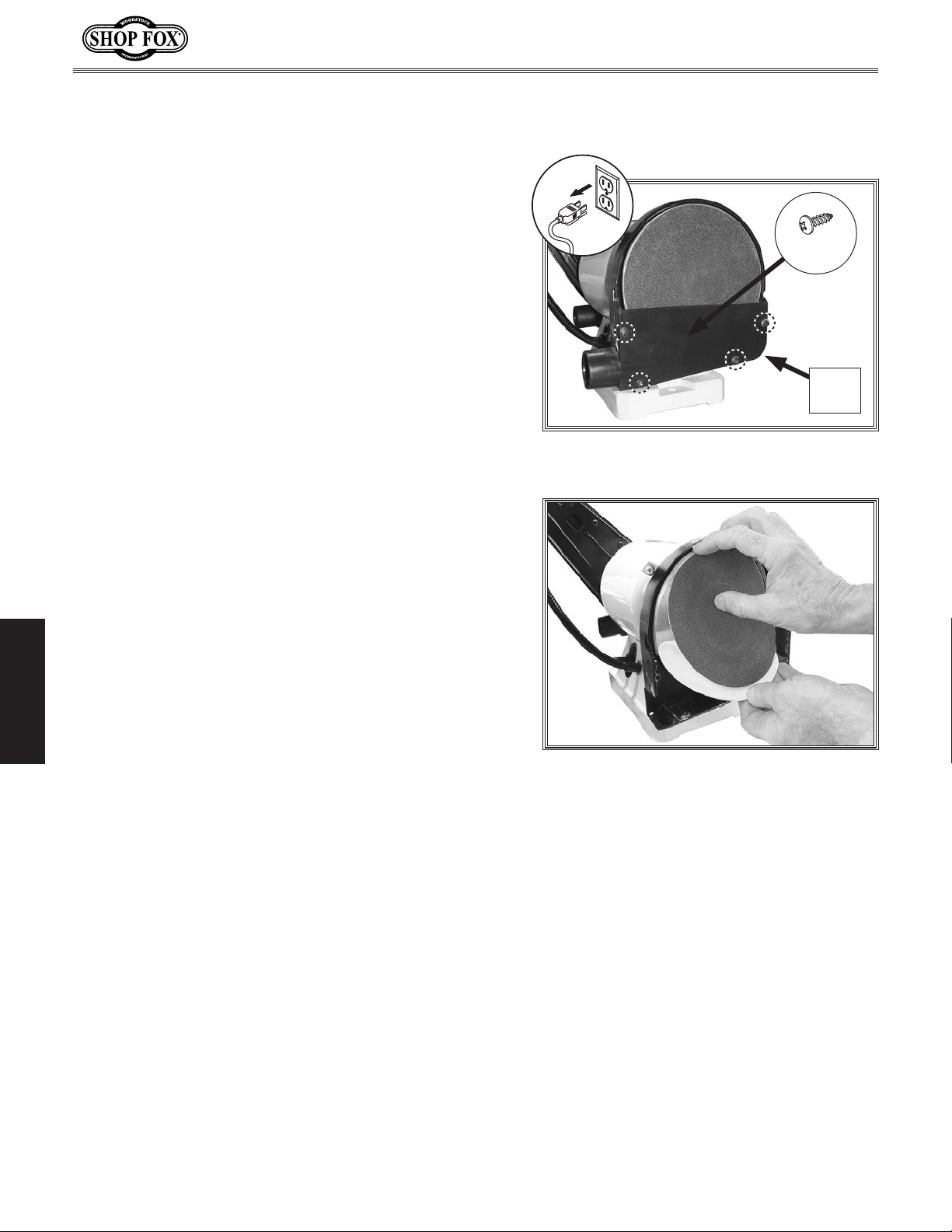
3. Remove (4) M4-.7 x 8 Phillips head screws and (4)
4mm washers, then remove disc cover (see Figure
18).
Remove worn out sandpaper by slowly peeling it
4.
from aluminum disc.
5. Make sure aluminum disc is thoroughly clean of all
OPERATIONS
substances, including solvent, before applying a
new sanding disc. If necessary, clean aluminum disc
with a light application of a non-oil, non-flammable
solvent to remove any adhesive residue.
.........................................1
Disc
Cover
Figure 18. Remove disc cover to access
sanding disc.
Figure 19. Installing sanding disc.
Peel back protective layer on half of sandpaper disc,
6.
and fold it against the remaining half.
Center sticky half of sandpaper on upper half of
7.
aluminum disc, and press sandpaper onto disc
surface (see
Remove remainder of protective layer, then press
8.
paper against aluminum disc.
Rotate disc by hand, making sure sandpaper is firmly
9.
attached to aluminum disc.
Re-install sanding disc table (see Page 13).
10.
Figure 19).
-20-
Page 24
Model W1838 (For Machines Mfd. Since 6/16)
Changing/Replacing
Sanding Belt
The Model W1838 Combo Sander accepts 27" x 2" sanding
belts. These are available in the current Shop Fox catalog
in a variety of grits.
The sanding belt runs across a 5" steel platen and is held
in place with a spring-tensioned release lever.
To change/replace sanding belt, do these steps:
DISCONNECT MACHINE FROM POWER!
1.
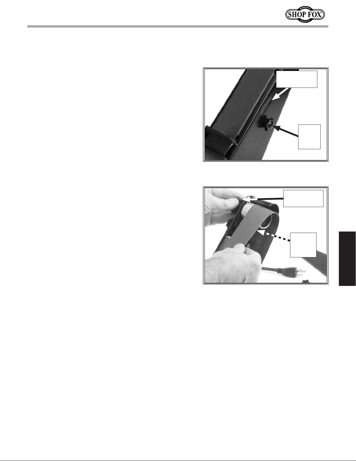
Remove side guard by completely unscrewing side-
2.
guard knob (see
Note: To provide further access to the lower drive
wheel, it is also possible to remove the front belt
guard.
Loosen belt tension lock knob (see Figure 21).
3.
Pull belt tension lever (see Figure 21) to loosen
4.
belt, them remove belt.
Install new sanding belt, then tighten belt tension
5.
lock knob, and re-install side guard.
Figure 20).
Belt Rotation
Arrow
Side
Guard
Knob
Figure 20. Side-guard knob and belt
rotation arrow location.
Belt Tension
Lock Knob
Belt
Tension
Lever
OPERATIONS
Note: Make sure arrow on inside of sanding belt
points same direction as belt rotation arrow on
machine.
Follow belt tracking procedure on Page 19.
6.
Figure 21. Changing/replacing belt.
-21-
Page 25
Model W1838 (For Machines Mfd. Since 6/16)
ACCESSORIES
Combination Sander Accessories
The following combination sander accessories may be available through your local Woodstock
International Inc. Dealer. If you do not have a dealer in your area, these products are also available
through online dealers. Please call or e-mail Woodstock International Inc. Customer Service to get a
current listing of dealers at: 1-800-840-8420 or at [email protected].
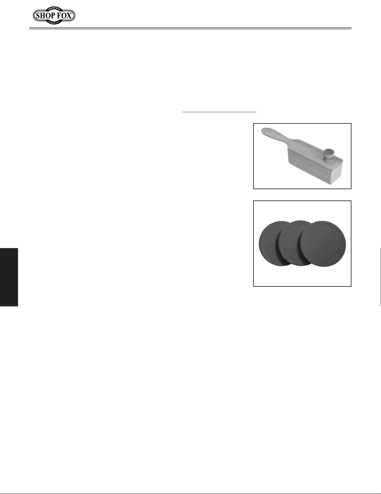
The W1309—PRO-STIK® 6" Abrasive Belt/Disk Cleaner with Handle
is the easiest solution for unloading abrasives. The 6" stick has a
knob on the end for those two-handed cleaning jobs. Both wooden
handles provide great control during abrasive belt cleaning. 6"
cleaner length and 11" overall length.
Shop Fox D1307 Sanding Disc—3-pack includes three 60-grit
The
aluminum oxide sanding discs, pre-applied with top-quality pressuresensitive adhesive. Sanding discs are also available under the
following part numbers:
D1308
D1309
D1310
D1311
D1312
D1313
80-grit aluminum oxide sanding disc - 3 pk.
100-grit aluminum oxide sanding disc - 3 pk.
120-gr it aluminum oxide sanding disc - 3 pk.
150-grit aluminum oxide sanding disc - 3 pk.
180-grit aluminum oxide sanding disc - 3 pk.
220-grit aluminum oxide sanding disc - 3 pk.
OPERATIONS
-22-
Page 26
Model W1838 (For Machines Mfd. Since 6/16)
MAINTENANCE
General
For optimum performance from your machine, follow
this maintenance schedule and refer to any specific
instructions given in this section.
Before & During Operation:
• Loose mounting bolts.
• Damaged, excessively worn, or clogged sandpaper.
Worn or damaged switch or wires.
•
• Excessive dust build-up.
• Efficiency of the dust collection system.
• Any other unsafe condition.
Cleaning & Protecting
MAKE SURE that your machine is
unplugged during all maintenance
procedures! If this warning is ignored,
serious personal injury may occur.
Cleaning the Model W1838 is relatively easy. Vacuum excess
wood chips and sawdust, and wipe off the remaining dust
with a dry cloth. If any resin has built up, use a resindissolving cleaner to remove it.
Lubrication
Extended use and sawdust can build up in sleeve bearings,
which cause wear. Use a high pressure oil can to lubricate
the sleeve bearing with 30 WT oil after every 10 hours
of operation. No other lubrication is necessary for this
machine.
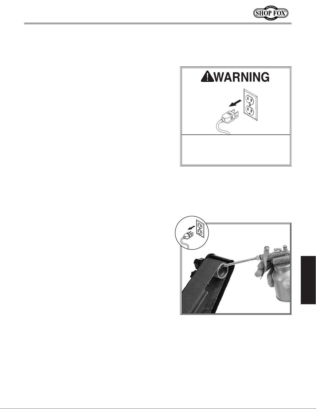
To lubricate sleeve bearings, do these steps:
DISCONNECT MACHINE FROM POWER!
1.
Remove sanding belt cover and sanding belt.
2.
3. Apply two or three drops of oil in hole at end of idler
pulley (see Figure 22).
Wipe off any residual oil.
4.
MAINTENANCE
Figure 22. Lubricating idler pulley sleeve
bearings.
Note: DO NOT apply extra oil. Too much oil can
cause the belt to slip.
-23-
Page 27

The following troubleshooting tables cover common problems that may occur with this machine. If you
need replacement parts or additional troubleshooting help, contact our Technical Support.
Note:
Before contacting Tech Support, find the machine serial number and manufacture date, and if
available, your original purchase receipt. This information is required to properly assist you.
Motor and Electrical
PROBLEM POSSIBLE CAUSE CORRECTIVE ACTION
Machine does not
start or a breaker
trips.
Machine stalls or is
underpowered.
Machine has vibration or noisy
operation.
SERVICE
SERVICE
Troubleshooting
1. Incorrect power supply voltage or circuit
size.
2. Power supply circuit breaker tripped or
fuse blown.
3. Motor wires connected incorrectly.
4. Wiring open/has high resistance.
5. ON/OFF switch at fault.
6. Run capacitor at fault.
7. Motor at fault.
1. Machine undersized for task.
2. Workpiece material not suitable for
machine.
3. Sanding with too much pressure.
4. Dust collection ducting problem, causing
dust buildup.
5. Dust collector undersized, causing dust
buildup.
6. Motor wired incorrectly.
7. Motor overheated.
8. Pulley/sprocket slipping on shaft.
1. Machine incorrectly mounted to workbench
or floor.
2. Sanding belt not tracking correctly.
3. Weak or broken tension spring.
4. Broken/defective sanding belt.
5. Sanding disc rubbing or not centered
properly.
6. Motor or component loose.
7. Motor bearings at fault.
Model W1838 (For Machines Mfd. Since 6/16)
1. Ensure correct power supply voltage and circuit
size (Page 9).
2. Ensure circuit is sized correctly and free of shorts.
Reset circuit breaker or replace fuse.
3. Correct motor wiring connections (Page 28).
4. Check/fix broken, disconnected, or corroded wires.
5. Replace switch.
6. Test/replace.
7. Test/repair/replace.
1. Clean/replace sandpaper; reduce feed rate/sanding depth.
2. Only sand wood—ensure moisture is below 20%.
3. Reduce pressure of workpiece against sanding belt/
disc.
4. Clear blockages, seal leaks, use smooth wall duct,
eliminate bends, close other branches.
5. Move closer to machine/redesign ducting layout/
upgrade dust collector.
6. Wire motor correctly (Page 27).
7. Clean motor, let cool, and reduce workload.
8. Replace loose pulley/shaft.
1. Adjust feet, shim, or tighten mounting hardware.
2. Adjust sanding belt tracking (Page 19).
3. Replace spring (Page 29)
4. Replace sanding belt (Page 21).
5. Center sanding disc; adjust work table to prevent
disc contact (Page 17).
6. Inspect/replace damaged bolts/nuts, and retighten
with thread locking fluid.
7. Test by rotating shaft; rotational grinding/loose
shaft requires bearing replacement.
-24-
Page 28

Model W1838 (For Machines Mfd. Since 6/16)
Operations
PROBLEM POSSIBLE CAUSE CORRECTIVE ACTION
Sanding grains easily
rub off belt or disc.
Deep sanding
grooves or scars in
workpiece.
Sanding belt/disc
clogs quickly or
burns workpiece.
Glazed sanding
sur face.
Burn marks on
workpiece.
Workpiece gets
pulled out of your
hand while belt
sanding.
Workpiece lifts up
from sanding disc
table.
Workpiece sanded
at wrong angle.
1. Sanding belt/disc has been stored in an
incorrect environment.
2. Sanding belt/disc has been smashed or
folded.
1. Sanding belt/disc too coarse for desired
finish.
2. Workpiece sanded across the grain.
3. Too much sanding force on workpiece.
4. Workpiece held still for too long against
belt/disc.
1. Too much pressure on sanding belt/disc.
2. Sanding softwood.
3. Sanding belt/disc clogged.
4. Sanding belt/disc worn or damaged.
1. Sanding wet stock.
2. Sanding stock with high amount of residue.
1. Sanding grit too fine.
2. Using too much pressure.
3. Workpiece held still for too long.
1. Not supporting workpiece against backstop.
1. Sanding on the upward spinning half of
sanding disc.
1. Miter gauge not set at correct angle; not
calibrated.
1. Store sanding belt/disc in a cool, dry area.
2. Store sanding belt/disc flat, and not bent or folded.
1. Use finer grit sanding belt/disc (Page 22).
2. Sand with grain.
3. Reduce pressure on workpiece while sanding.
4. Keep workpiece moving while sanding.
1. Reduce pressure of workpiece against sanding belt/
disc.
2. Use different stock, or accept characteristics of
stock and plan to clean/replace sanding belt/disc
frequently.
3. Clean sanding belt/disc (Page 22).
4. Replace sanding disc/belt (Pages 20 & 21).
1. Only sand dry stock.
2. Use different stock, or accept characteristics of
stock and plan to clean/replace sanding belt/disc
frequently.
1. Use coarser grit sanding belt/disc (Page 22).
2. Reduce pressure of workpiece against sanding belt/
disc.
3. Keep workpiece moving while sanding.
1. Use backstop to support workpiece.
1. Sand on downward spinning half of sanding disc.
1. Set miter gauge to correct angle; calibrate milter
gauge (Page 26).
-25-
SERVICE
Page 29
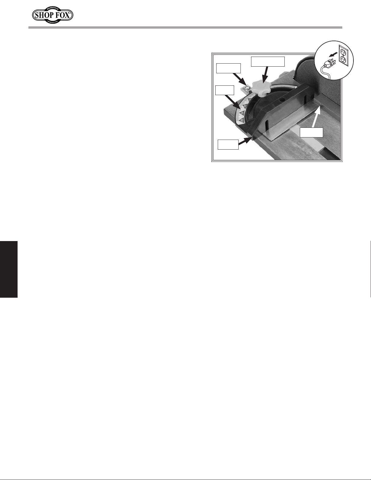
Calibrating Miter Gauge
Model W1838 (For Machines Mfd. Since 6/16)
At 90˚, the miter gauge should be perpendicular to the
face of the disc when it is mounted in the X-axis table
slot. If it is not, follow this procedure to recalibrate it.
Tools Needed:
90° Square .......................................................1
Phillips Head Screwdriver
To calibrate miter gauge, do these steps:
DISCONNECT MACHINE FROM POWER!
1.
2. Ensure sanding table is set at 0°, as covered in
Setting Table Angle on Page 17.
Set one edge of a 90° square against face of miter
3.
gauge and other edge against disc face, as shown in
Figure 23.
Loosen lock knob on miter gauge and adjust face
4.
of miter gauge so it is flush with edge of square,
tighten miter gauge lock knob, and verify setting.
.....................................1
Lock Knob
Pointer
Scale
Square
Fence
Figure 23. Squaring miter gauge to disc.
OPERATIONS
Loosen degree scale pointer, position pointer on 90˚,
5.
and retighten screw.
Recheck miter scale accuracy with square.
6.
-26-
Page 30
Model W1838 (For Machines Mfd. Since 6/16)
These pages are current at the time of printing. However, in the spirit of improvement, we may make
changes to the electrical systems of future machines. Compare the manufacture date of your machine to
If there are differences between your machine and what is shown in this section, call Technical Support
for assistance BEFORE making any changes to the wiring on your machine. An updated
machine before calling. This information can be found on the main machine label.
Electrical Safety Instructions
the one stated in this manual, and study this section carefully.
at (360) 734-3482
wiring diagram may be available. Note: Please gather the serial number and manufacture date of your
SHOCK HAZARD. Working on wiring that is
connected to a power source is extremely
dangerous. Touching electrified parts will
result in personal injury including but not
limited to severe burns, electrocution,
or death. Disconnect the power from
the machine before servicing electrical
components!
QUALIFIED ELECTRICIAN. Due to the inherent
hazards of electricity, only a qualified
electrician should perform wiring tasks on
this machine. If you are not a qualified
electrician, get help from one before
attempting any kind of wiring job.
WIRE CONNECTIONS. All connections must
be tight to prevent wires from loosening
during machine operation. Double-check all
wires disconnected or connected during any
wiring task to ensure tight connections.
WIRE/COMPONENT DAMAGE. Damaged wires
or components increase the risk of serious
personal injury, fire, or machine damage. If
you notice that any wires or components are
damaged while performing a wiring task,
replace those wires or components before
completing the task.
MODIFICATIONS. Using aftermarket parts or
modifying the wiring beyond what is shown
in the diagram may lead to unpredictable
results, including serious injury or fire.
MOTOR WIRING. The motor wiring shown
in these diagrams is current at the time
of printing, but it may not match your
machine. Always use the wiring diagram
inside the motor junction box.
CAPACITORS/INVERTERS. Some capacitors
and power inverters store an electrical
charge for up to 10 minutes after being
disconnected from the power source.
To reduce the risk of being shocked,
wait at least this long before working on
capacitors.
CIRCUIT REQUIREMENTS. You MUST follow
the requirements at the beginning of this
manual when connecting your machine to a
power source.
EXPERIENCING DIFFICULTIES. If you are
experiencing difficulties understanding
the information included in this section,
contact our Technical Support at
(360) 734-3482.
SERVICE
WIRING DIAGRAM COLOR KEY
The photos and diagrams
included in this section are
best viewed in color. You
can view these pages in
color at www.shopfox.biz.
BLACK
WHITE
GREEN
RED
BLUE
BROWN
GRAY
ORANGE
-27-
YELLOW
YELLOW
GREEN
PURPLE
PINK
LIGHT
BLUE
BLUE
WHITE
TURQUOISE
Page 31
Model W1838 (For Machines Mfd. Since 6/16)
OFF
ON
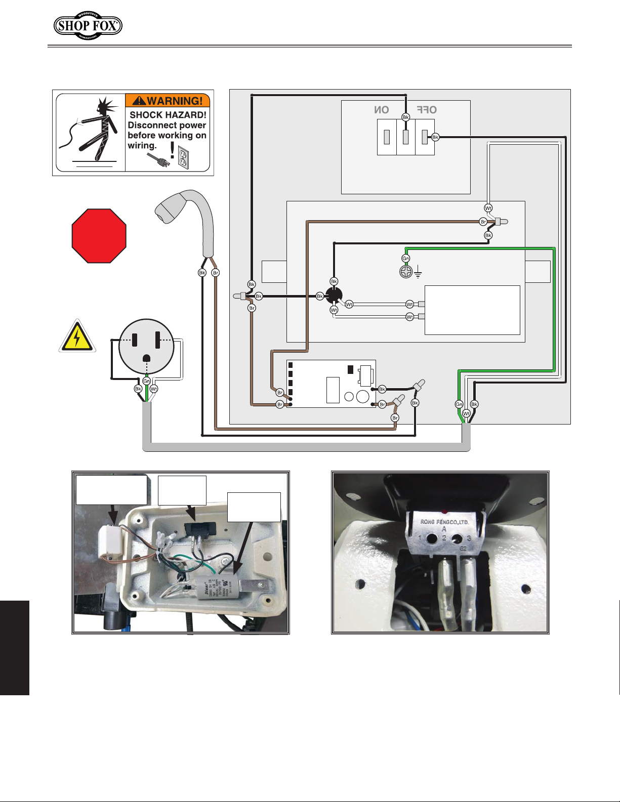
Wiring Diagram
Read
Page 27
STOP
Before
Wiring
120 VAC
5-15 Plug
Work
Lamp
Lamp
Circuit
Board
(Switch
viewed
from
behind)
1 2 3
ON/OFF Switch
Rong Fengco LTD.
RF-1001 T-85
10A/250V
Motor 120V
Ground
Run Capacitor
CBB60 SH
10MFD
300VAC
Lamp
Circuit Board
ON/OFF
Switch
Run
Capacitor
Figure 24. Main wiring.
Figure 25. ON/OFF switch wiring (viewed
from behind).
SERVICE
-28-
Page 32
Model W1838 (For Machines Mfd. Since 6/16)
PARTS
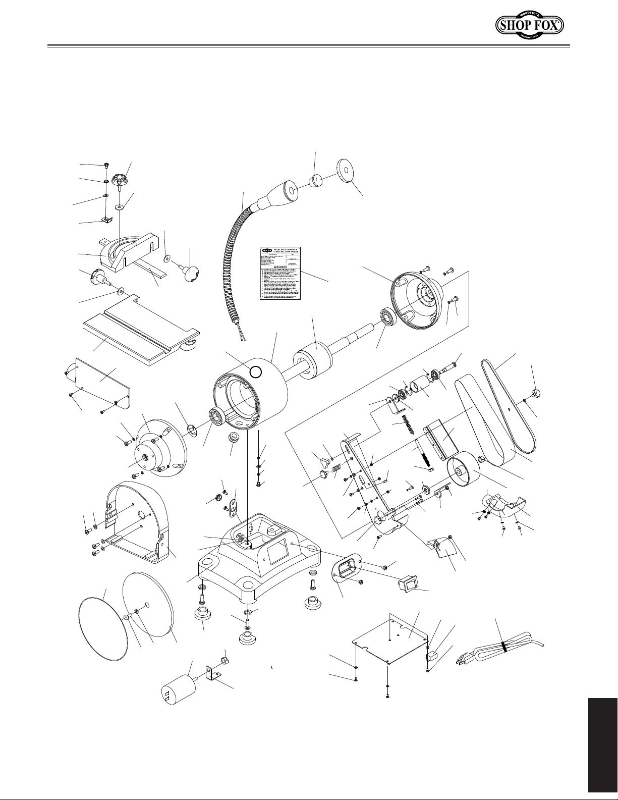
Main Parts Breakdown
15
14
7
17
16
21
78
79
13
11
18
16
16
18
22
26
46
34
77
76
49
52
48
39
61
54
43
7
70
40
19
59
56
65
53
34
53
51
42
20
24
57
57
56
58
55
68
71
7
6
72
48
15
66
67
80
7
41
31
60
61
52
62
63
64
69
34
9
9
12
25
74
36
73
30
24
32
81
15
44
38
29
28
75
35
34
33
9
45
47
1
10
9
7
6
22
7
43
2
23
8
27
4
3
5
37
9
PARTS
-29-
Page 33
Model W1838 (For Machines Mfd. Since 6/16)
System Parts List
REF PART # DESCRIPTION REF PART # DESCRIPTION
1 X1838001 WORK TABLE 41 X1838041 BOTTOM PLATE
2 X1838002 SANDPAPER DISC 6" PSA 80-GRIT AO 42 X1838042 LED LIGHT TRANSFORMER
3 X1838003 CAP SCREW M6-1 X 16 43 X1838043 PHLP HD SCR M5-.8 X 20
4 X1838004 INT TOOTH WASHER 6MM 44 X1838044 PHLP HD SCR M6-1 X 20
5 X1838005 SANDING DISC 45 X1838045 KNOB M8-1.25 3-LOBE
6 X1838006 PHLP HD SCR M5-.8 X 12 46 X1838046 FLAT WASHER 8MM
7 X1838007 LOCK WASHER 5MM 47 X1838047 KNOB M6-1 X 10 6-LOBE
8 X1838008 DISC GUARD 48 X1838048 PHLP HD SCR M5-.8 X 12
9 X1838009 PHLP HD SCR M4-.7 X 8 49 X1838049 INNER BELT GUARD
10 X1838010 DISC COVER W/DUST PORT 51 X1838051 BOTTOM DRIVE WHEEL GUARD
11 X1838011 MITER GAUGE BODY 52 X1838052 FENDER WASHER 5MM
12 X1838012 MITER GAUGE SLIDE 53 X1838053 FLANGE NUT M5-.8
13 X1838013 MITER GAUGE INDICATOR 54 X1838054 TENSION PLATE
14 X1838014 EXT TOOTH WASHER 5MM 55 X1838055 IDLER SHAFT SPACER
15 X1838015 PHLP HD SCR M5-.8 X 8 56 X1838056 BALL BEARING 6201-2RS
16 X1838016 FLAT WASHER 6MM 57 X1838057 INT RETAINING RING 32MM
17 X1838017 KNOB M6-1 X 22 6-LOBE 58 X1838058 IDLER WHEEL/DRUM
18 X1838018 KNOB M6-1 X 18 2-LOBE 59 X1838059 IDLER SHAFT
19 X1838019 HEX NUT M3-.5 60 X1838060 GUARD COVER
20 X1838020 PHLP HD SCR M3-.5 X 10 61 X1838061 KNOB M5-.8 X 10 3-LOBE
21 X1838021 LAMP ASSEMBLY 62 X1838062 SANDING BELT 2 X 27 80-GRIT AO
22 X1838022 MOTOR END CAP 63 X1838063 HEX NUT M12-1.75
23 X1838023 WAVY WASHER 35MM 64 X1838064 DRIVE WHEEL
24 X1838024 BALL BEARING 6202-ZZ 65 X1838065 PLATEN
25 X1838025 STATOR 66 X1838066 TENSIONING ROD M8-1.25
26 X1838026 ROTOR 67 X1838067 HEX NUT M8-1.25
27 X1838027 BASE 68 X1838068 COMPRESSION SPRING 65 X 14 X 1.85MM
28 X1838028 CORD CLIP FIXED PLATE 69 X1838069 DUST PORT 1-1/2
29 X1838029 CORD BUSHING 70 X1838070 TOOL REST
30 X1838030 STRAIN RELIEF TYPE-1 10MM 71 X1838071 HEX NUT M4-.7
31 X1838031 POWER CORD 16G 3W 72" 5-15P 72 X1838072 HEX NUT M6-1
32 X1838032 RUBBER FOOT 73 X1838073 LOCK WASHER 10MM
33 X1838033 LOCK WASHER 4MM 74 X1838074 HEX NUT M10-1
34 X1838034 FLAT WASHER 4MM 75 X1838075 LOCK WASHER 6MM
35 X1838035 INT TOOTH WASHER 4MM 76 X1838076 MACHINE ID LABEL
36 X1838036 R CAPACITOR 9M 300V 1-3/8 X 2 77 X1838077 COMPRESSION SPRING 9 X 14 X 0.5MM
37 X1838037 CAPACITOR MOUNTING BRACKET 78 X1838078 LED BULB
38 X1838038 HEX NUT M8-1.25 79 X1838079 LENS
39 X1838039 SWITCH PLATE 80 X1838080 DRIVE WHEEL WASHER 13 X 26 X 5MM
40 X1838040 ON/OFF SWITCH, RONG FENG RF-001 T-85 81 X1838081 TOUCH-UP PAINT, SHOP FOX WHITE
PARTS
-30-
Page 34

Model W1838 (For Machines Mfd. Since 6/16)
Page 35

FOLD ALONG DOTTED LINE
FOLD ALONG DOTTED LINE
Place
Stamp
Here
Woodstock international inc.
p.o. box 2309
bellingham, Wa 98227-2309
TAPE ALONG EDGES--PLEASE DO NOT STAPLE
Page 36

WARRANTY
Woodstock International, Inc. warrants all Shop Fox machinery to be free of defects from workmanship
and materials for a period of two years from the date of original purchase by the original owner.
This warranty does not apply to defects due directly or indirectly to misuse, abuse, negligence or
accidents, lack of maintenance, or reimbursement of third party expenses incurred.
Woodstock International, Inc. will repair, replace, or arrange for a dealer refund, at its expense and
option, the Shop Fox machine or machine part proven to be defective for its designed and intended
use, provided that the original owner returns the product prepaid to an authorized warranty or repair
facility as designated by our Bellingham, Washington office with proof of their purchase of the product
within two years, and provides Woodstock International, Inc. reasonable opportunity to verify the
alleged defect through inspection. If it is determined there is no defect, or that the defect resulted
from causes not within the scope of Woodstock International Inc.'s warranty, then the original owner
must bear the cost of storing and returning the product.
This is Woodstock International, Inc.’s sole written warranty and any and all warranties that may be
implied by law, including any merchantability or fitness, for any particular purpose, are hereby limited
to the duration of this written warranty. We do not warrant that Shop Fox machinery complies with
the provisions of any law, acts or electrical codes. We do not reimburse for third party repairs. In no
event shall Woodstock International, Inc.’s liability under this limited warranty exceed the purchase
price paid for the product, and any legal actions brought against Woodstock International, Inc. shall be
tried in the State of Washington, County of Whatcom. We shall in no event be liable for death, injuries
to persons or property or for incidental, contingent, special or consequential damages arising from the
use of our products.
Every effort has been made to ensure that all Shop Fox machinery meets high quality and durability
standards. We are commited to continuously improving the quality of our products, and
right to change specifications at any time
WARRANTY
.
reserve the
Page 37

 Loading...