

Page 1
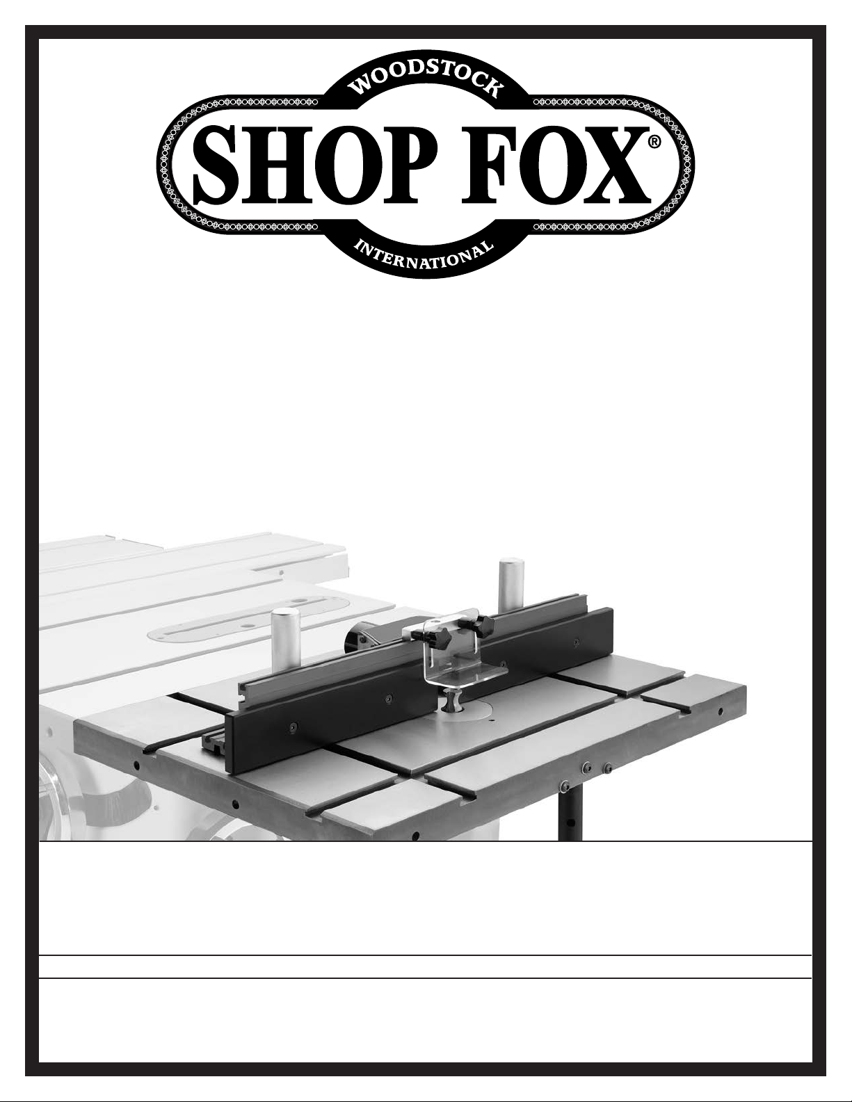
MODEL W1821
ROUTER TABLE
ATTACHMENT
#12866TS
OWNER'S MANUAL
(FOR MODELS MANUFACTURED SINCE 3/16)
Phone: (360) 734-3482 • Online Technical Support: [email protected]
COPYRIGHT © JULY, 2010 BY WOODSTOCK INTERNATIONAL, INC. REVISED APRIL, 2016 (BL)
WARNING: NO PORTION OF THIS MANUAL MAY BE REPRODUCED IN ANY SHAPE OR FORM WITHOUT
THE WRITTEN APPROVAL OF WOODSTOCK INTERNATIONAL, INC.
Printed in China
Page 2
This manual provides critical safety instructions on the proper setup,
operation, maintenance, and service of this machine/tool. Save this
document, refer to it often, and use it to instruct other operators.
Failure to read, understand and follow the instructions in this manual
may result in fire or serious personal injury—including amputation,
electrocution, or death.
The owner of this machine/tool is solely responsible for its safe use.
This responsibility includes but is not limited to proper installation in
a safe environment, personnel training and usage authorization,
proper inspection and maintenance, manual availability and comprehension, application of safety devices, cutting/sanding/grinding tool
integrity, and the usage of personal protective equipment.
The manufacturer will not be held liable for injury or property
damage from negligence, improper training, machine modifications or
misuse.
Some dust created by power sanding, sawing, grinding, drilling, and
other construction activities contains chemicals known to the State of
California to cause cancer, birth defects or other reproductive harm.
Some examples of these chemicals are:
• Lead from lead-based paints.
• Crystalline silica from bricks, cement and other masonry products.
• Arsenic and chromium from chemically-treated lumber.
Your risk from these exposures varies, depending on how often you
do this type of work. To reduce your exposure to these chemicals:
Work in a well ventilated area, and work with approved safety equipment, such as those dust masks that are specially designed to filter
out microscopic particles.
Page 3

Contents
INTRODUCTION .....................................2
Woodstock Technical Support .................. 2
Specifications ..................................... 2
SAFETY ............................................... 3
Standard Machinery Safety Instructions ...... 3
Standard Machinery Safety ..................... 3
Additional Safety for Router Tables ........... 5
SETUP ................................................ 6
Unpacking ......................................... 6
Inventory .......................................... 6
Assembly ........................................... 7
Router Installation ............................. 11
OPERATIONS....................................... 12
General .......................................... 12
Operation Overview ........................... 13
Workpiece Inspection .......................... 13
Edge Jointing ................................... 14
Groove Cutting ................................. 15
Routing Small Stock ............................ 16
Free-Hand Routing ............................. 17
ACCESSORIES ...................................... 19
Router Table Attachment Accessories ....... 19
MAINTENANCE .................................... 20
General .......................................... 20
Cleaning & Protecting ......................... 20
PARTS .............................................. 21
Table ............................................. 21
Fence ............................................. 22
WARRANTY ........................................ 25
SAFETYINTRODUCTION
SETUP MAINTENANCE
OPERATIONS
USE THE QUICK GUIDE PAGE LABELS TO SEARCH OUT INFORMATION FAST!
PARTS
Page 4
Model W1821 (For Machines Mfd. Since 3/16)
INTRODUCTION
INTRODUCTION
Woodstock Technical Support
The Model W1821 has been specially designed to provide many years of trouble-free service. Close
attention to detail, ruggedly built parts and a rigid quality control program assure safe and reliable
operation.
Woodstock International, Inc. is committed to customer satisfaction. Our intent with this manual is to
include the basic information for safety, setup, operation, maintenance, and service of this product.
We stand behind our machines! In the event that questions arise about your machine, please
contact Woodstock International Technical Support at (360) 734-3482 or send e-mail to:
[email protected]. Our knowledgeable staff will help you troubleshoot problems and
process warranty claims.
If you need the latest edition of this manual, you can download it from http://www.woodstockint.com
If you have comments about this manual, please contact us at:
Woodstock International, Inc.
Attn: Technical Documentation Manager
P.O. Box 2309
Bellingham, WA 98227
Email: [email protected]
The Model W1821 Router Table Attachment mounts to most table saws that have 27" deep tables. This
addition to your table saw features a universal router mount, a 20" by 27" precision-ground cast iron
table, an extruded aluminum fence, and a starting pin for contour shaping. Included with the W1821 are
double-cross
3
⁄4" x 3⁄8" T-slots, an adjustable support leg, and a dust port for 2 1⁄2" or 3" flexible hose.
Specifications
Table Size .............................................. 20" x 27"
Table T-Slot Size ......................................
Fence Board Size (x 2) .......................... 12
Number of Table Inserts .......................................2
Table Insert Inside Openings ......................... 1", 2
Table Opening Size ............................................4"
Router Base Thickness Range .......................
Dust Port Size......................................... 2
3
⁄4" x 3⁄8"
1
⁄2" x 2 3⁄4"
3
1
⁄4"–2 1⁄4"
1
⁄2" & 3"
⁄8"
Fits the following Shop Fox Model table saws: W1677, W1703, W1711, W1714, W1725, W1726, W1748,
W1817, W1818, W1819, W1820 (may fit additional models as they are released).
NOTICE
The Model W1821 mounts on most table saws that have 27" deep tables. If your table saw does
not have mounting holes for the installation of the router table, you will need to drill and tap
these holes. Read the entire assembly section before you begin the installation procedure to
make sure the W1821 will fit your table saw.
-2-
Page 5
SAFETY
SAFETY
OWNER’S MANUAL.
TRAINED OPERATORS ONLY.
DANGEROUS ENVIRONMENTS.
MENTAL ALERTNESS REQUIRED.
electrical components or improperly grounded
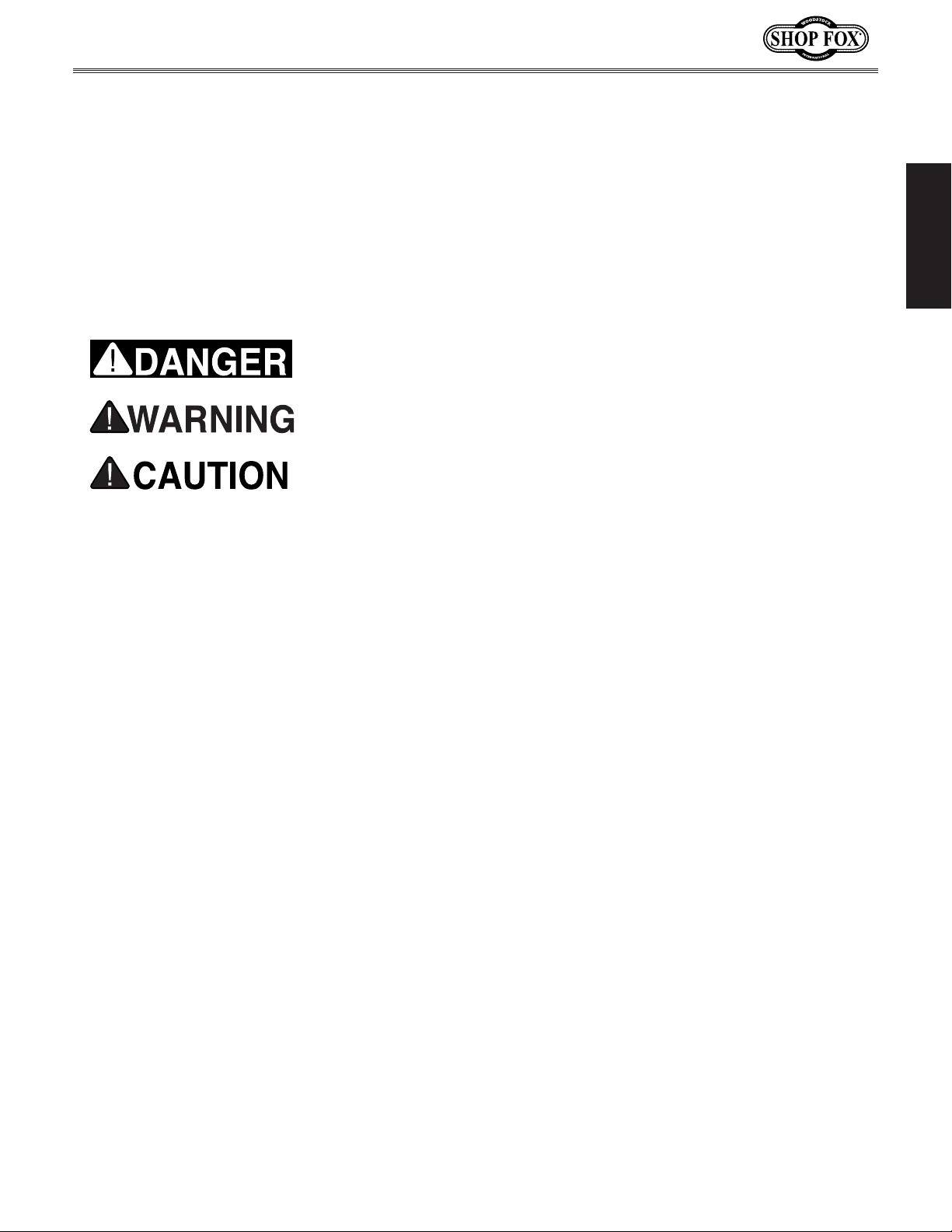
manual uses a series of symbols and signal words intended to convey the level of importance of the
safety messages. The progression of symbols is described below. Remember that safety messages by
Model W1821 (For Machines Mfd. Since 3/16)
SAFETY
For Your Own Safety,
Machinery Safety
Read Manual Before Operating Machine
The purpose of safety symbols is to attract your attention to possible hazardous conditions. This
themselves do not eliminate danger and are not a substitute for proper accident prevention measures—this responsibility is ultimately up to the operator!
NOTICE
Standard Machinery Safety Instructions
Standard Machinery Safety Instructions
Indicates an imminently hazardous situation which, if not avoided,
WILL result in death or serious injury.
Indicates a potentially hazardous situation which, if not avoided,
COULD result in death or serious injury.
Indicates a potentially hazardous situation which, if not avoided,
MAY result in minor or moderate injury.
This symbol is used to alert the user to useful information about
proper operation of the equipment or a situation that may cause
damage to the machinery.
SAFETY
Read and understand this
owner’s manual BEFORE using machine.
have a higher risk of being hurt or killed. Only
allow trained/supervised people to use this
machine. When machine is not being used,
disconnect power, remove switch keys, or
lock-out machine to prevent unauthorized
use—especially around children. Make
workshop kid proof!
machinery in areas that are wet, cluttered,
or have poor lighting. Operating machinery
in these areas greatly increases the risk of
accidents and injury.
alertness is required for safe operation of
machinery. Never operate under the influence
of drugs or alcohol, when tired, or when
distracted.
Untrained operators
Do not use
Full mental
ELECTRICAL EQUIPMENT INJURY RISKS. You can
be shocked, burned, or killed by touching live
machinery. To reduce this risk, only allow an
electrician or qualified service personnel to
do electrical installation or repair work, and
always disconnect power before accessing or
exposing electrical equipment.
DISCONNECT POWER FIRST. Always disconnect
machine from power supply BEFORE making
adjustments, changing tooling, or servicing
machine. This eliminates the risk of injury
from unintended startup or contact with live
electrical components.
EYE PROTECTION. Always wear ANSI-approved
safety glasses or a face shield when operating
or observing machinery to reduce the risk of
eye injury or blindness from flying particles.
Everyday eyeglasses are not approved safety
glasses.
-3-
Page 6

WEARING PROPER APPAREL. Do not wear
clothing, apparel, or jewelry that can become
HAZARDOUS
HEARING PROTECTION.
REMOVE ADJUSTING TOOLS.
INTENDED USAGE.
AWKWARD POSITIONS.
CHILDREN & BYSTANDERS.
GUARDS & COVERS.
FORCING MACHINERY. Do not force machine. It
will do the job safer and better at the rate for
loss of control. Before starting, verify machine
malfunction, leading to serious personal injury
from heated surfaces, high traffic areas, harsh
entangled in moving parts. Always tie back
or cover long hair. Wear non-slip footwear to
avoid accidental slips, which could cause loss
of workpiece control.
DUST. Dust created while using
SAFETY
machinery may cause cancer, birth defects,
or long-term respiratory damage. Be aware of
dust hazards associated with each workpiece
material, and always wear a NIOSH-approved
respirator to reduce your risk.
Always wear hearing
protection when operating or observing
loud machinery. Extended exposure to this
noise without hearing protection can cause
permanent hearing loss.
Tools left on
machinery can become dangerous projectiles
upon startup. Never leave chuck keys,
wrenches, or any other tools on machine.
Always verify removal before starting!
Only use machine for its
intended purpose—never make modifications
without prior approval from Woodstock
International. Modifying machine or using
it differently than intended will void the
warranty and may result in malfunction or
mechanical failure that leads to serious
personal injury or death!
Keep proper footing and
balance at all times when operating machine.
Do not overreach! Avoid awkward hand
positions that make workpiece control difficult
or increase the risk of accidental injury.
Keep children and
bystanders at a safe distance from the work
area. Stop using machine if they become a
distraction.
Model W1821 (For Machines Mfd. Since 3/16)
which it was designed.
NEVER STAND ON MACHINE. Serious injury may
occur if machine is tipped or if the cutting
tool is unintentionally contacted.
STABLE MACHINE. Unexpected movement during
operation greatly increases risk of injury or
is stable and mobile base (if used) is locked.
USE RECOMMENDED ACCESSORIES. Consult
this owner’s manual or the manufacturer for
recommended accessories. Using improper
accessories will increase risk of serious injury.
UNATTENDED OPERATION. To reduce the risk
of accidental injury, turn machine OFF and
ensure all moving parts completely stop
before walking away. Never leave machine
running while unattended.
MAINTAIN WITH CARE. Follow all maintenance
instructions and lubrication schedules to
keep machine in good working condition. A
machine that is improperly maintained could
or death.
CHECK DAMAGED PARTS. Regularly inspect
machine for any condition that may affect
safe operation. Immediately repair or replace
damaged or mis-adjusted parts before
operating machine.
MAINTAIN POWER CORDS. When disconnecting
cord-connected machines from power, grab
and pull the plug—NOT the cord. Pulling the
cord may damage the wires inside, resulting
in a short. Do not handle cord/plug with wet
hands. Avoid cord damage by keeping it away
chemicals, and wet/damp locations.
accidental contact with moving parts or flying
debris—make sure they are properly installed,
undamaged, and working correctly.
Guards and covers reduce
EXPERIENCING DIFFICULTIES. If at any time
you experience difficulties performing the
intended operation, stop using the machine!
-4-
Contact Technical Support at (360) 734-3482.
Page 7
Model W1821 (For Machines Mfd. Since 3/16)
Additional Safety for Router Tables
AVOIDING AMPUTATION. Never place hands
directly over or in front of the cutter. As one
hand approaches the cutter, move it away.
Always keep hand at least 6" away from the
spinning cutter.
SECURING LEVERS AND KNOBS. Never operate
the router table without first making sure
that all lock levers and knobs are tight, and
that all fence hardware and guide rails are
secure. Otherwise, the workpiece can slip out
of alignment during cutting and cause injury
from kickback.
PREVENTING WORKPIECE DRAW-INKICKBACK.
Always feed the workpiece against the
rotation of the cutter. Never force materials
past the router. Let the cutter do the work.
Excessive force is likely to result in poor
cutting results and will cause kickback
conditions that could cause serious personal
injury.
APPROPRIATE WORKPIECES. The danger of
kickback and injury is increased when the
workpiece has knots, holes, or foreign objects
in it. Warped stock should be run through a
jointer before you run it through the router
table.
BLIND CUTTING. Keep the cutter on the
underside of the workpiece when making
blind cuts, which decreases risk of accidental
contact with the cutter.
TESTING ROTATION. With the machine
disconnected from power, rotate the router
spindle to test any new setup to ensure proper
cutter clearance before starting the machine.
CUTTING SUPPORT. NEVER cut a workpiece
without using a fence, jig, or miter.
Otherwise, the workpiece can be grabbed by
the cutter and pull your hands into the cutter.
WORKPIECE SIZING. NEVER use a workpiece
shorter than six inches without special fixtures
or jigs. Otherwise, the workpiece can become
trapped between the fence and cutter, which
could draw your hands into the spinning
cutter.
CUTTER HEIGHT. Keep any unused portion of the
cutter below the table surface, or a workpiece
can be grabbed by the cutter causing kickback
and serious injury.
USING SAFETY GUARDS. To prevent amputation
or other injuries, NEVER remove any
guards or 10 when machine is operating.
Fabricate additional guards or jigs for special
circumstances. Use an overhead guard if the
fence is removed.
TRIPPING HAZARD. To prevent tripping over the
router power cord when operating the table
saw, always disconnect it and safely store it
out of the way.
SAFETY
READ and understand this
entire manual before using
this machine. Serious personal injury may occur
if safety and operational
information is not understood and followed. DO
NOT risk your safety by
not reading!
USE this and other machinery with caution and respect. Always consider safety
first, as it applies to your individual working conditions. No list of safety guidelines
can be complete—every shop environment
is different. Failure to follow guidelines
could result in serious personal injury,
damage to equipment or poor work results.
-5-
Page 8
SETUP
Unpacking
The Model W1821 has been carefully packaged for safe
transportation. If you notice the product has been
damaged during shipping, please contact your authorized
Shop Fox dealer immediately.
Inventory
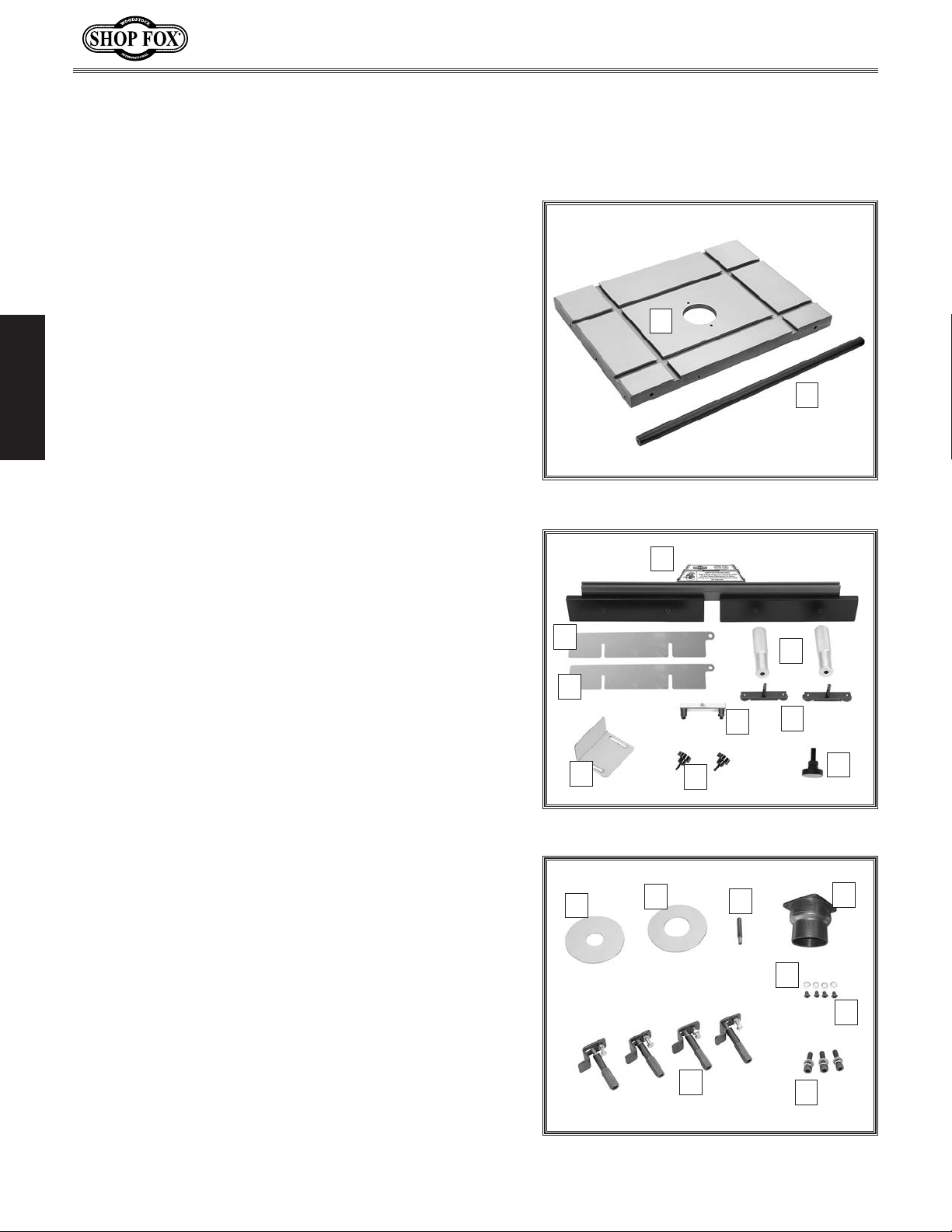
Refer to Figures 1–3 and the listing below to inventory
the contents of the shipping box.
SETUP
If you can't find an item on this list, check the mounting
locations or examine the packaging materials carefully.
Occasionally we pre-install certain components for
shipping purposes.
Model W1821 (For Machines Mfd. Since 3/16)
A
B
Figure 1. Shipping inventory items A–B.
If any nonproprietary parts are missing (e.g. a nut or a
washer), we will gladly replace them; or for the sake of
expediency, replacements can be obtained at your local
hardware store.
Description Qty
A. Router Table ................................................1
B. Support Leg .................................................1
C. Fence & Dust Hood ........................................1
D. Knurled Fence Handles ...................................2
E. T-Slot Bars ..................................................2
F. Router Guard Bracket Assembly .........................1
G. Fence Board Shim 1.5mm ................................1
H. Fence Board Shim 0.7mm ................................1
I. Plastic Router Guard ......................................1
J. Router Guard Star Knobs .................................2
K. Support Leg Foot Pad Assembly .........................1
L. Table Insert 1" ID ..........................................1
M. Table Insert 2
N. Starting Pin .................................................1
O. Dust Port 2
P. Button Head Cap Screws M5-.8 x 12 ...................4
Q. Flat Washers 5mm .........................................4
R. Mounting Screw Assemblies ..............................3
— Cap Screws M8-1.25 x 30 ..............................3
— Lock Washers 8mm ................................ ......3
— Flat Washers 8mm.......................................3
S. Router Hold-Down Assemblies ...........................4
3
⁄8" ID .......................................1
1
⁄2" & 3" .......................................1
C
G
H
F
I
Figure 2. Shipping inventory items C–K.
L
J
M
S
N
D
E
K
O
Q
P
R
-6-
Figure 3. Shipping inventory items L–S.
Page 9
Model W1821 (For Machines Mfd. Since 3/16)
Assembly
The Model W1821 mounts on most table saws that have
27" deep tables. If your table saw does not have mounting
holes for the installation of the router table, you will
need to drill and tap these holes. Also, you may have to
modify the fence rails to allow access for the router table
T-slots. Read this entire assembly section before you begin
the installation procedure below to make sure the W1821
will fit your table saw before making any modifications.
Needed for Assembly Qty
Another Person ..................................................1
Hex Wrench 4mm ...............................................1
Hex Wrench 5mm ...............................................1
Hex Wrench 6mm ...............................................1
Wrench 10mm ...................................................1
Wrench 13mm ...................................................2
Straightedge (at least 24" long) ..............................1
To assemble and install your router table attachment,
do these steps:
Saw Table
Mounting Holes
SETUP
Router Table
Figure 4. Mounting holes in saw and router
tables.
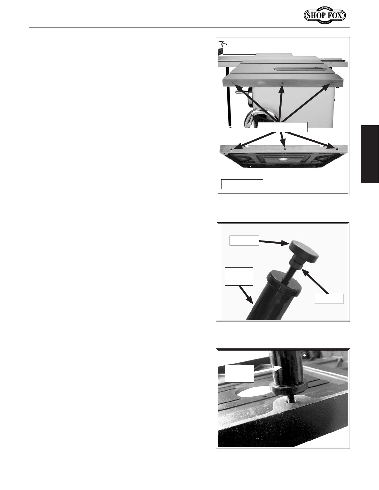
1. DISCONNECT THE TABLE SAW FROM POWER!
2. Decide which of the following mounting options best
suits your needs:
— Remove the existing right wing of the saw table
and use the existing wing mounting holes to attach
the router table.
— Mount the router table to the right side of the
saw table or the existing right-hand wing. In
these cases, you will probably need to drill and
tap three M8-1.25 holes into the saw table or
wing that match those in the router table (see
Figure 4).
Tip: Use the holes in the router table as a template
for marking the mounting hole locations on the saw
table so that the router table top will mount flush
with the top of the saw table.
3. Thread the foot pad assembly into the bottom of the
support leg, as shown in Figure 5. For now, do not
tighten the jam nut up to the leg so that you can
adjust the height of the leg in a later step.
Foot Pad
Support
Leg
Jam Nut
Figure 5. Example of foot pad threaded
into support leg.
Support
Leg
4. Thread the support leg onto the stud on the bottom
of the router table, as shown in Figure 6.
-7-
Figure 6. Support leg threaded into the
router table.
Page 10
Model W1821 (For Machines Mfd. Since 3/16)
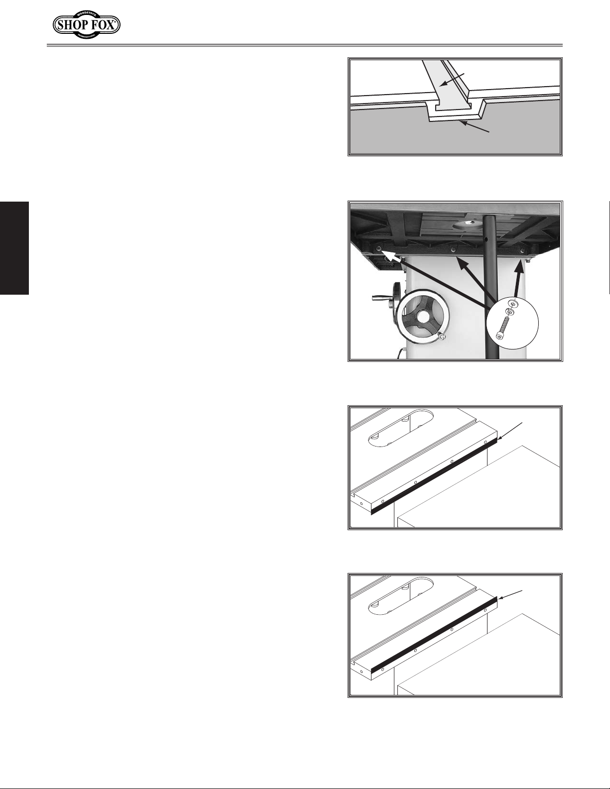
5. If you have long fence rails that will extend beyond
the T-slots of the router table, you will have to
modify the top of the rails. This entails making a
cut-out that matches or exceeds the dimensions of
the router table T-slot, as shown in the illustration in
Figure 7.
Also, drill mounting holes through the rails that
match the holes in the side of the router table.
6. With the help of another person to hold the table
and leg assembly, align the mounting holes in
both tables and secure them together with the (3)
M8-1.25 x 30mm cap screws, (3) 8mm lock washers,
and (3) 8mm flat washers, as shown in Figure 8.
SETUP
— If you have fence rails that extend beyond the
saw table and across the router table, use the
mounting holes you drilled in Step 5 to fasten the
rails to the router table.
Router Table T-Slot
Fence Rail
Cut-Out
Figure 7. Illustrated example of a fence
modification.
x 3
7. Place the straightedge across the saw table and
router table to make sure that the combined table
surface is flat.
— If the combined table surface is flat, continue
with Step 8.
— If the outside edge of the router table tilts down,
place strips of masking tape along the bottom
edge of the saw table to shim the router table up
and even with the saw table from side to side (see
Figure 9).
— If the outside edge of the router table tilts up,
place strips of masking tape along the top edge
of the saw table to shim the router table down
and even with the saw table from side to side
(see Figure 10).
Note: After reinstalling the router table, remove all
excess masking tape with a razor blade.
Figure 8. Router table attached to the
table saw.
Tape
Figure 9. Using tape to shim the router
table up.
Tape
-8-
Figure 10. Positioning the tape to shim
the router table down.
Page 11
Model W1821 (For Machines Mfd. Since 3/16)
8. When the saw and router tables are level with each
other, rotate the foot pad assembly so that it sits
firmly on the floor without changing the height of
the router table. Tighten the jam nut of the foot pad
assembly up to the leg bottom to secure the setting.
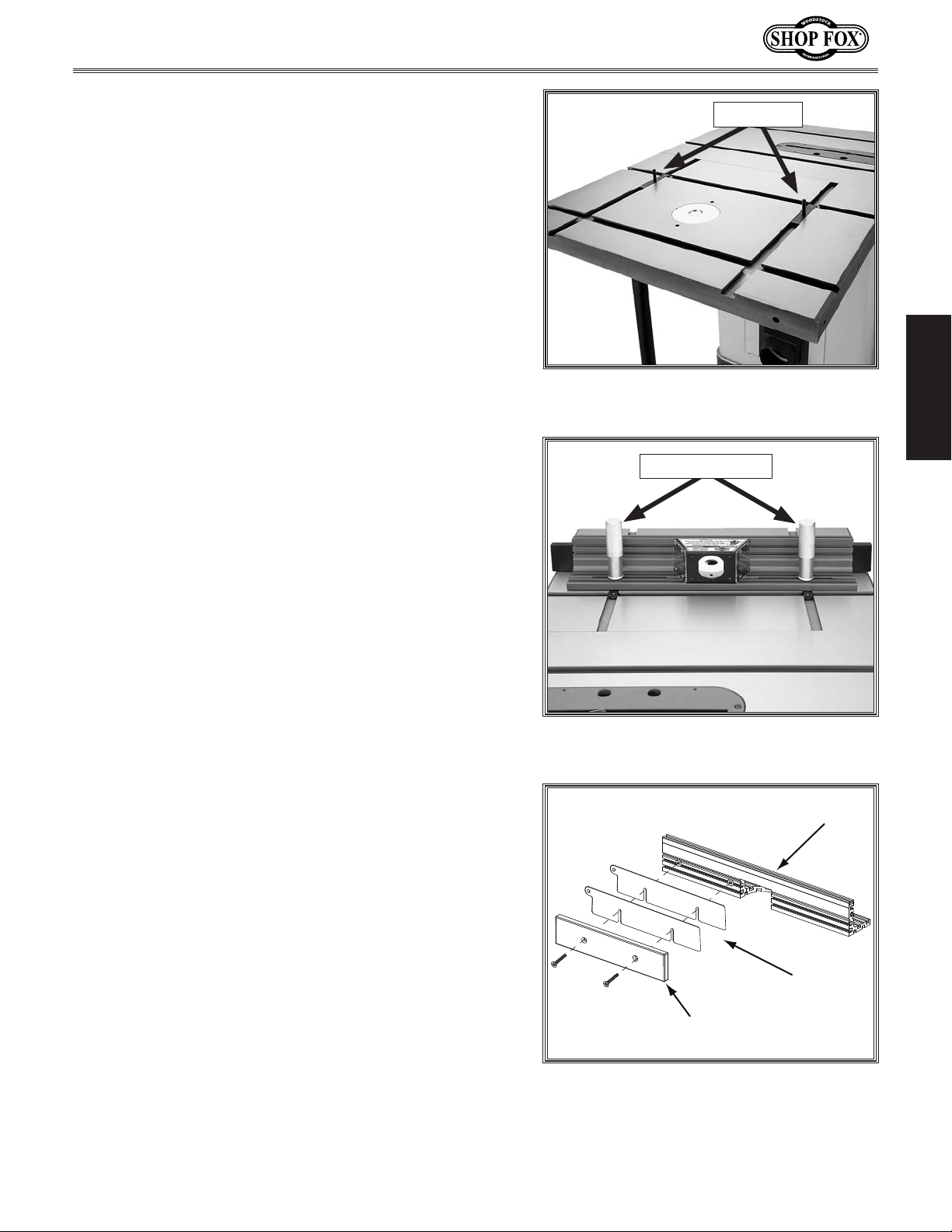
9. Slide the two T-slot bars into the T-slots of the
router table (see Figure 11).
Note: The router table double-cross T-slots offer
four different orientations for the router fence—
choose the one that best suits your operation.
10. Place the fence assembly over the studs of the T-slot
bars, then secure the fence in place by threading
the knurled handles onto the studs, as shown in
Figure 12.
T-Slot Bars
SETUP
Figure 11. T-slot bars installed for one of
four orientations.
Knurled Handles
Note: The two fence board shims provided with your
router table can be placed between the outfeed
fence board (left) and the fence to offset the
outfeed fence board for full edge routing (see the
illustration in Figure 13 and refer to Edge Routing
on Page 14 for additional details).
With additional shop-made shims, the outfeed fence
board can be offset up to approximately 4mm from
the infeed board. If you require more offset, you
can obtain longer M6-1 flat head screws to secure
the outfeed fence board.
Figure 12. Fence knurled handles
installed.
Fence
Shims
Outfeed
Fence Board
Figure 13. Shim installation for full edge
routing.
-9-
Page 12
DO NOT operate the attached router without an
adequate dust collection system. Follow your router
manufacturer's specifications for the required dust
collection capacity. Failure to use a dust collection
system can result in short and long-term respiratory
illness.
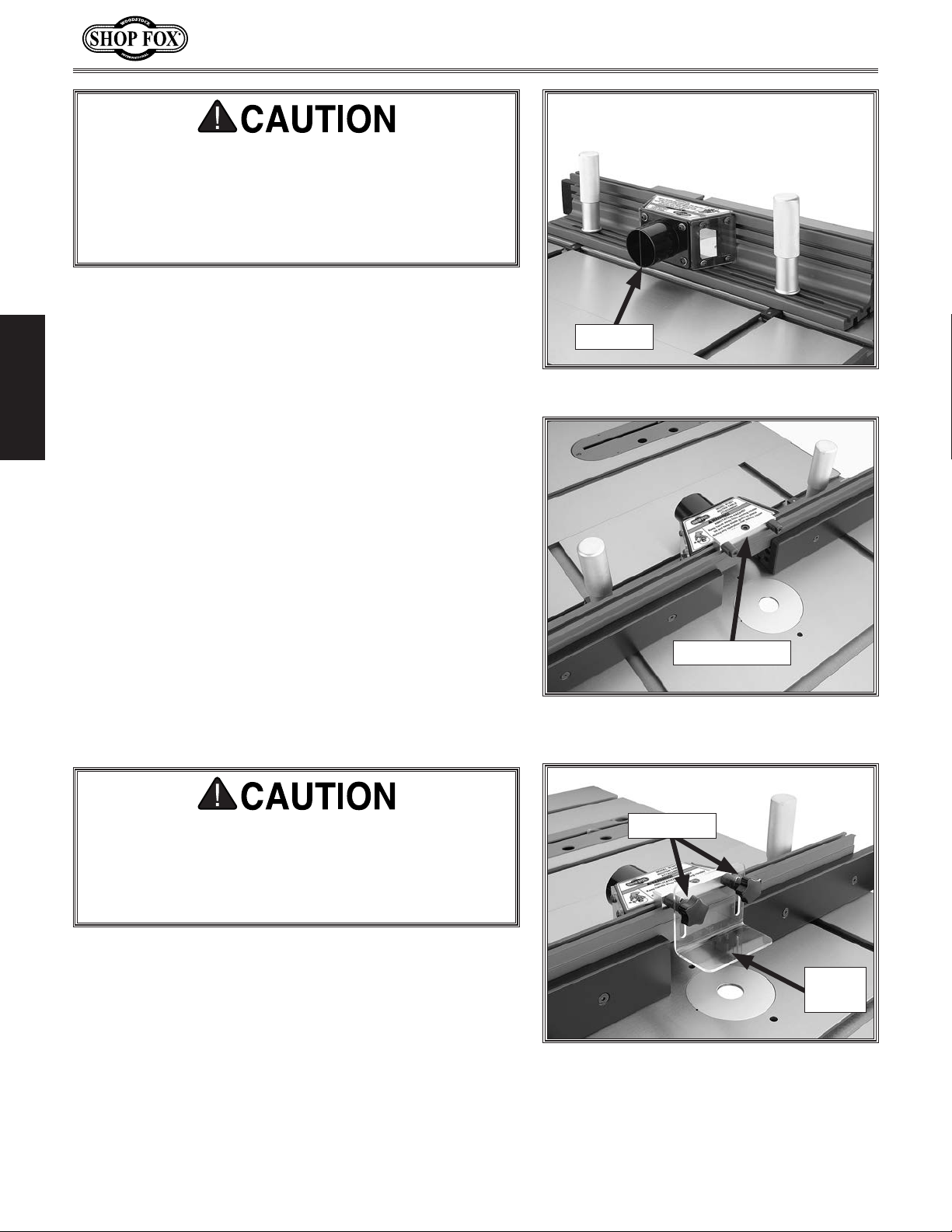
11. Attach the dust port to the back of the fence
assembly with the (4) M5-.8 x 12 cap screws and (4)
5mm flat washers, as shown in Figure 14.
SETUP
12. Slide the attached square nut on the guard bracket
into the top fence T-slot, center it with the dust
hood and dust port, then tighten the cap screw to
secure it in place, as shown in Figure 15.
Model W1821 (For Machines Mfd. Since 3/16)
Dust Port
Figure 14. Dust port installed.
To reduce the risk of hand injury from accidental
contact with the spinning router bit, with the
exception of freehand routing, ALWAYS make sure
the fence and router guard are properly positioned
and secured before connecting the router to power.
13. Attach the plastic router guard to the guard bracket
with the (2) star knob bolts, as shown in Figure 16.
Guard Bracket
Figure 15. Guard bracket attached to the
fence.
Star Knobs
Router
Guard
Figure 16. Router guard installed.
-10-
Page 13
Model W1821 (For Machines Mfd. Since 3/16)
Router Installation
The Model W1821 will support a router with a base
thickness between
To install a router, do these steps:
1. DISCONNECT THE SAW AND ROUTER FROM POWER!
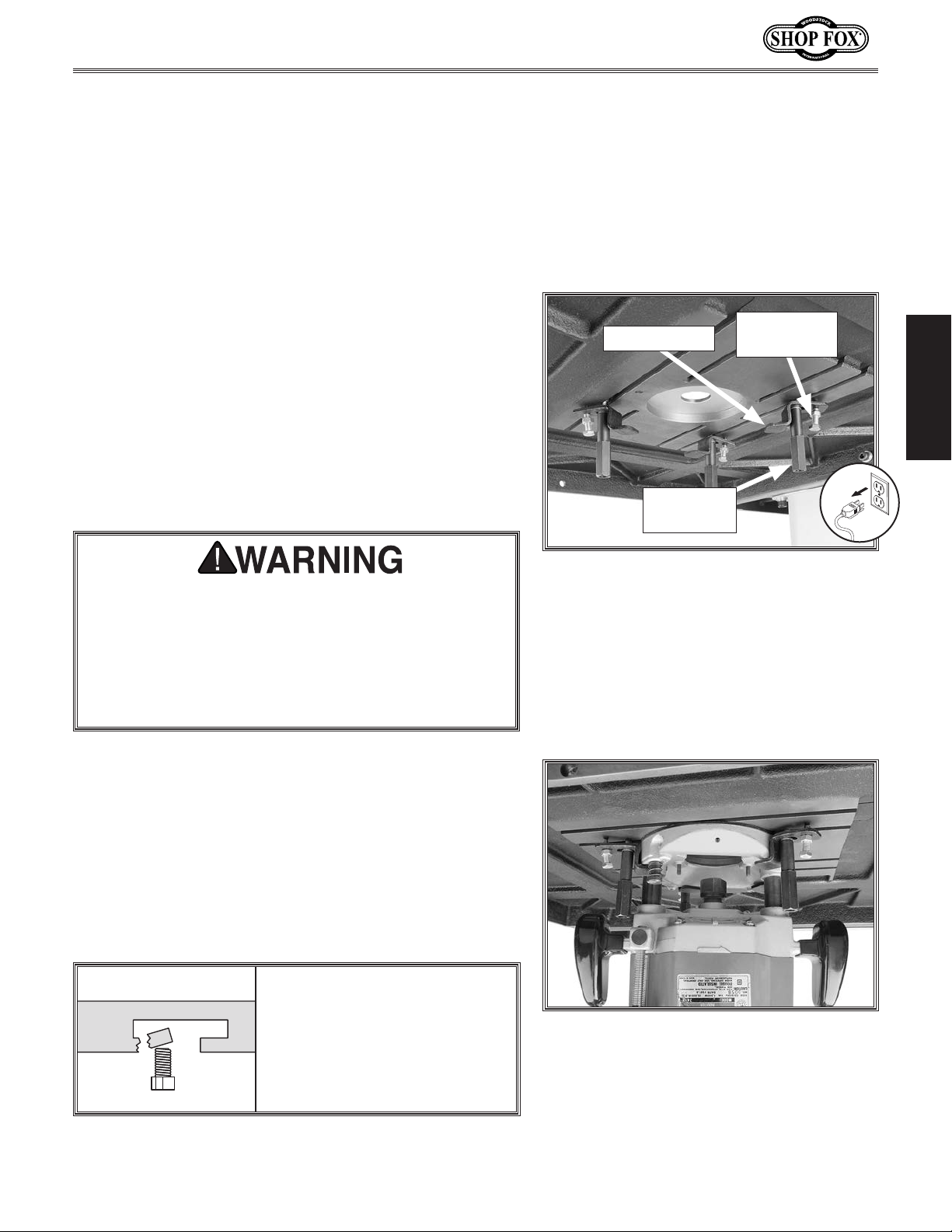
2. Slide three of the router hold-down assemblies into
the T-slots underneath the router table so that they
allow room for the router base, as shown in Figure
17.
Note: To properly position the hold-down clamp,
balance the tightness of the hold-down knob and the
adjustment bolt so that the clamp will allow room
for the router base in the next step. If necessary,
put the adjustment bolt jam nut on the other side
of the clamp.
If the router unexpectedly moves or the router bit
contacts the table insert or fence during operation,
serious personal injury could result from flying
debris. ALWAYS make that at least three router
clamps are used and are applied to a flat surface
of the router base before connecting the router to
power.
1
⁄4" and 2 1⁄4".
Router Clamp
Hold-Down
Knob
Figure 17. Router hold-down assembly
controls.
Adjustment
Bolt
SETUP
3. Slide the router base onto the three hold-down
clamps, position them so that they secure the router
bit in the center of the table opening, then tighten
the hold-down knobs and adjustment bolts to secure
the router in place (see Figure 18).
4. Install the remaining hold-down assembly to
make sure the router stays firmly in place during
operation.
NOTICE
To prevent damage to the
router table T-slots, do not
position the clamp adjustment
bolts over the thin edge of the
T-slots.
-11-
Figure 18. Router properly installed.
Page 14
OPERATIONS
General
Your router will perform many types of operations that
are beyond the scope of this manual. Many of these
operations can be dangerous or deadly if performed
incorrectly.
The instructions in this section are written with the
understanding that the operator has the necessary
knowledge and skills to operate the router with this
router table attachment. If at any time you are
experiencing difficulties performing any operation,
stop using the machine!
If you are an inexperienced operator, we strongly
recommend that you read books or trade articles, or
seek training from an experienced router operator before
performing any unfamiliar operations. Above all, your
safety should come first!
Model W1821 (For Machines Mfd. Since 3/16)
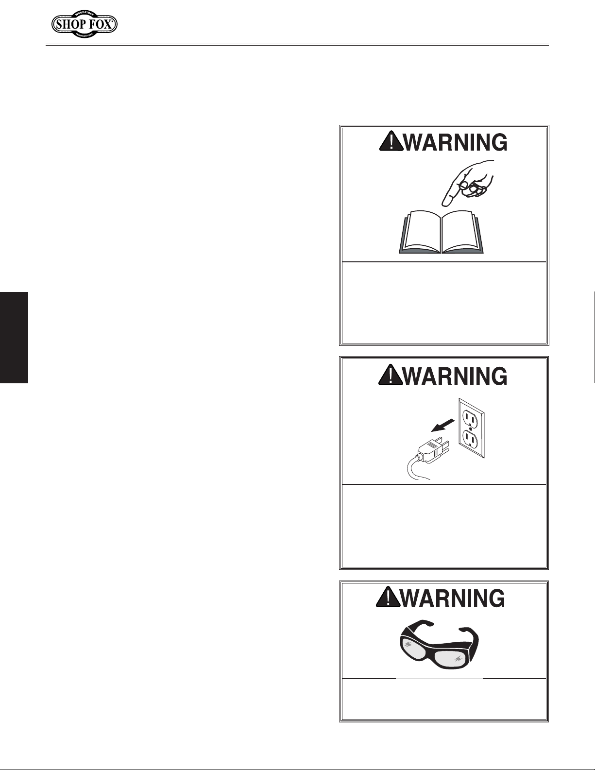
READ and understand this entire instruction manual before using this machine.
Serious personal injury may occur if
safety and operational information is not
understood and followed. DO NOT risk
your safety by not reading!
OPERATIONS
DO NOT investigate problems or adjustments while the router is running.
Wait until the router is turned OFF,
unplugged and all working parts
have come to a complete stop before
proceeding!
-12-
Always wear safety glasses when operating this machine. Failure to comply
may result in serious personal injury.
Page 15

Model W1821 (For Machines Mfd. Since 3/16)
Operation Overview Workpiece Inspection
This overview outlines you the basic process that
happens during an operation with the router
table attachment. Familiarize yourself with this
process to better understand the remaining
parts of the Operation section.
To complete a typical operation, the operator
does the following:
1. Examines the workpiece to make sure it is
suitable for cutting.
2. Adjusts the fence boards close to the bit
for maximum workpiece support, and then
secures the fence boards in place.
3. Adjusts the bit height for the desired
cutting profile.
4. Adjusts the fence position to establish the
depth of cut.
5. Wears safety glasses and a respirator, and
locates push sticks if needed.
6. If using a reversible router, verifies that the
direction of spindle rotation is correct, and
then starts the router.
7. Holds the workpiece firmly and flatly
against the fence, and then pushes the
workpiece into the bit at a steady and
controlled rate until the workpiece moves
completely beyond it.
Important: The operator is very careful
to keep the workpiece firmly against the
table and fence during the entire cut.
For smaller workpieces or odd-shaped
workpieces, a zero-clearance fence or jig is
used.
8. Stops the router.
Some workpieces are not safe to cut or may
require modification before routing. Before
routing, inspect all workpieces for the following:
• Material Type: This router is intended
for cutting natural and man-made wood
products, laminate covered wood products,
and some plastics. This machine is NOT
designed to cut metal, glass, stone, tile,
etc.
• Foreign Objects: Nails, staples, dirt,
rocks and other foreign objects are often
embedded in wood. While shaping, these
objects can become dislodged and hit the
operator, cause kickback, or break the bit,
which might then fly apart. Always visually
inspect your workpiece for these items.
If they can't be removed, DO NOT cut the
workpiece.
• Large/Loose Knots: Loose knots may
dislodge during a cutting operation. Knots
can cause kickback and machine damage.
Choose workpieces that do not have large/
loose knots or plan ahead to avoid shaping
through them.
• Wet or "Green" Stock: Routing wood
with a moisture content over 20% causes
unnecessary wear on the cutters, increases
the risk of kickback, and yields poor
results.
• Excessive Warping: Workpieces with
excessive cupping, bowing, or twisting are
dangerous to cut because they are unstable
and often unpredictable when being
shaped. DO NOT process workpieces with
these characteristics unless you properly
square up the stock with a jointer and
planer.
• Minor Warping: Workpieces with slight
cupping can be safely supported if the
cupped side is facing the table or the
fence. A workpiece supported on the bowed
side will rock during a cut and could cause
kickback or severe injury.
OPERATIONS
-13-
Page 16
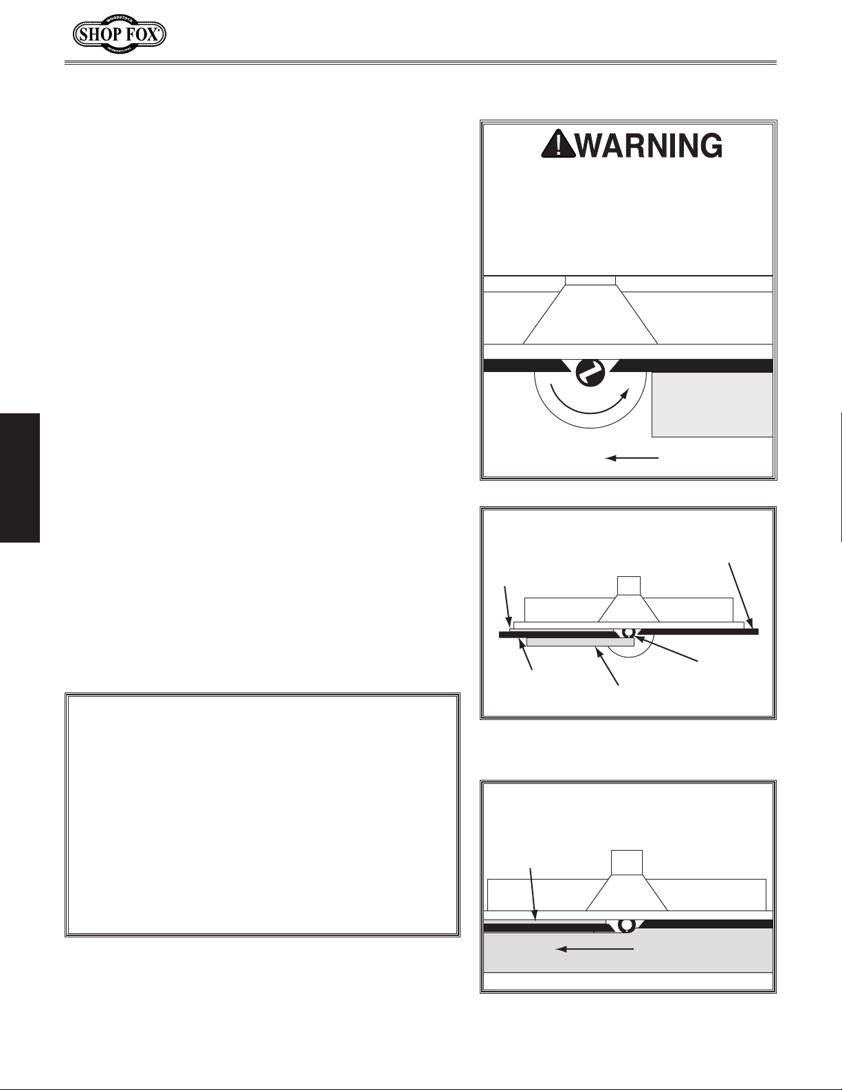
Edge Jointing
Jointing the edge of a board involves using a straight
cutting router bit to remove wood from the face of the
board. The result is a perfectly flat and square edge.
To joint the edge of a workpiece, do these steps:
1. DISCONNECT ROUTER FROM POWER!
2. Secure a straight cutting bit into your router
according to the router manufacturer's instructions.
3. Install the smallest table insert into the router table
that still allows the router bit to freely rotate.
4. Raise the bit to a height slightly more than that
of the workpiece, then rotate it by hand until the
cutting flute is perpendicular to the fence boards.
Model W1821 (For Machines Mfd. Since 3/16)
Always feed the workpiece against
the router bit rotation direction, as
illustrated below. Otherwise, the
workpiece could be aggressively pulled
from your hands, drawing them into the
spinning cutter.
Bit
Rotation
Workpiece
5. Insert and secure shims between the outfeed fence
board and the fence bracket that equal in thickness
the amount of material you want to remove from the
workpiece face (see the illustration in Figure 19).
OPERATIONS
6. Place a straightedge against the outfeed fence
board, then adjust the fence assembly so that
the straightedge is also against the bit flute, as
illustrated in Figure 19.
7. Lock the fence assembly in place, tighten all knobs,
connect the router to power, then perform the cut
(see Figure 20).
NOTICE
If you are using a mobile base with the table saw, use
one of the options below when moving the saw and
the router table attachment:
• Attach an extension to the mobile base that
will provide support for the router table leg.
• Install a locking caster onto the bottom of the
router table leg.
• Adjust the router table leg foot up, move the
unit, then re-adjust the foot to provide proper
support to the router table.
Feed Direction
Top View
Shim
Outfeed
Fence Board
Figure 19. Fence jointer setup (guard
removed for clarity).
Straightedge
Infeed
Fence Board
Straight
Router Bit
Top View
Shim
-14-
Cutting Direction
Figure 20. Edge jointing (guard removed
for clarity).
Page 17
Model W1821 (For Machines Mfd. Since 3/16)
Groove Cutting
Groove cutting produces a groove or bead into the face of
the board.
To cut a groove into the face of the workpiece, do
these steps:
1. DISCONNECT ROUTER FROM POWER!
2. Secure the bit into the router according to the
router manufacturer's instructions.
Top View
3. Install the smallest table insert into the table that
still allows the bit to freely rotate.
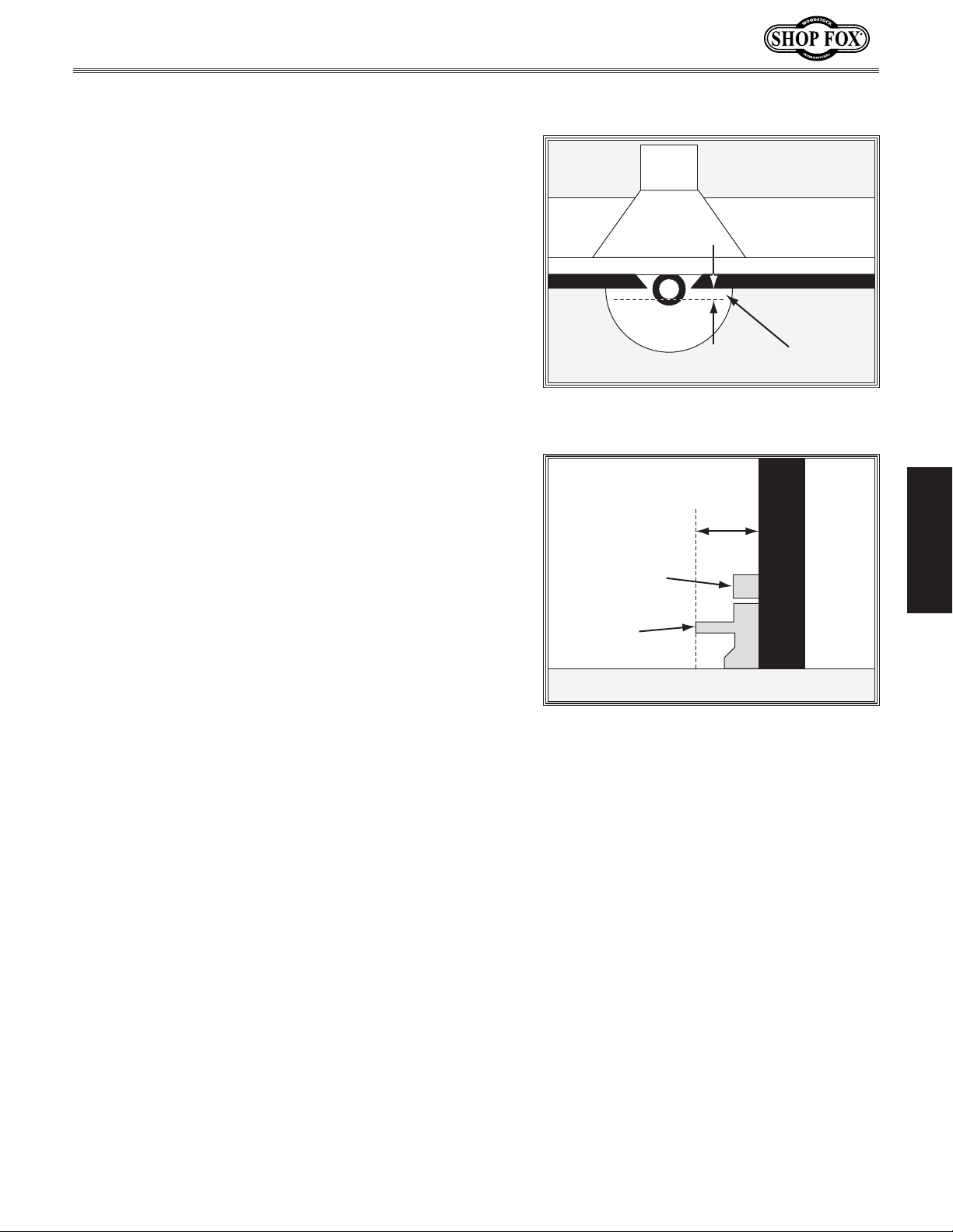
4. Make sure both fence boards are even with one
another and secured to the fence assembly.
5. Raise the bit to the desired height, then adjust the
fence assembly so that the fence boards are behind
the bit the same distance as the desired depth-ofcut (see the illustrations in Figures 21–22).
6. Lock the fence assembly in place, tighten all knobs,
connect the router to power, then perform the cut.
Depth-of-Cut
Figure 21. Groove cutting setup—top view
(guard removed for clarity).
Depth-of-Cut
Side View
Rub Collar
Bit
Table
Figure 22. Groove cutting setup—side view
(guard removed for clarity).
Fence
OPERATIONS
-15-
Page 18
Routing Small Stock
Feeding small stock past the router bit is always
dangerous. If you must route small stock, use a zeroclearance fence. This will provide greater protection for
the operator, better workpiece support, and reduced tear
out on narrow or fragile stock.
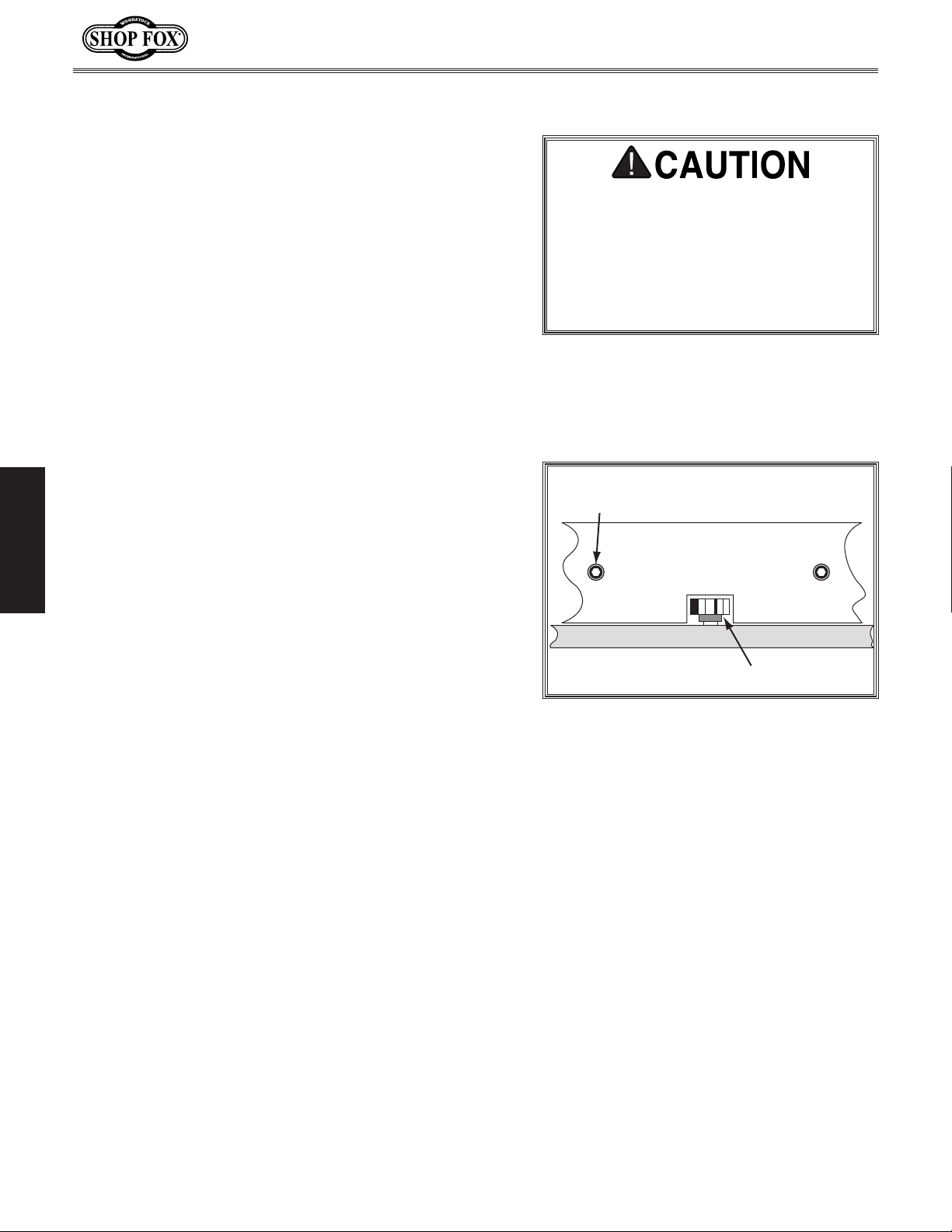
To make a zero-clearance fence, do these steps:
1. DISCONNECT ROUTER FROM POWER!
2. Remove the fence boards from the fence assembly.
3. Select a piece of straight and smooth stock that is
the same height and thickness as the fence boards
and approximately 24" long.
4. Cut an outline of the spindle and cutter from the
center of the stock selected in Step 3, as illustrated
in Figure 23.
Model W1821 (For Machines Mfd. Since 3/16)
ALWAYS use hold-downs or featherboards
and push sticks when shaping small or
narrow stock. These devices keep your
hands away from the spinning cutter
and sufficiently support the stock to
allow a safe and effective cut, reducing
the risk of personal injury.
Mounting
Fastener
Note: Make the outline as close as possible to the
cutter and spindle without interfering with rotation.
OPERATIONS
5. Create countersunk mounting holes in the zeroclearance fence so that the screws and T-nuts from
the split fence can be used to secure it to the fence
assembly in the same manner.
6. Secure the zero-clearance fence to the fence
assembly, check for proper clearance, connect the
router to power, then run a test piece by the cutter
to verify the results.
Zero-Clearance Fence
Table
Cutter
Figure 23. Example of a zero-clearance
fence.
-16-
Page 19
Model W1821 (For Machines Mfd. Since 3/16)
Free-Hand Routing
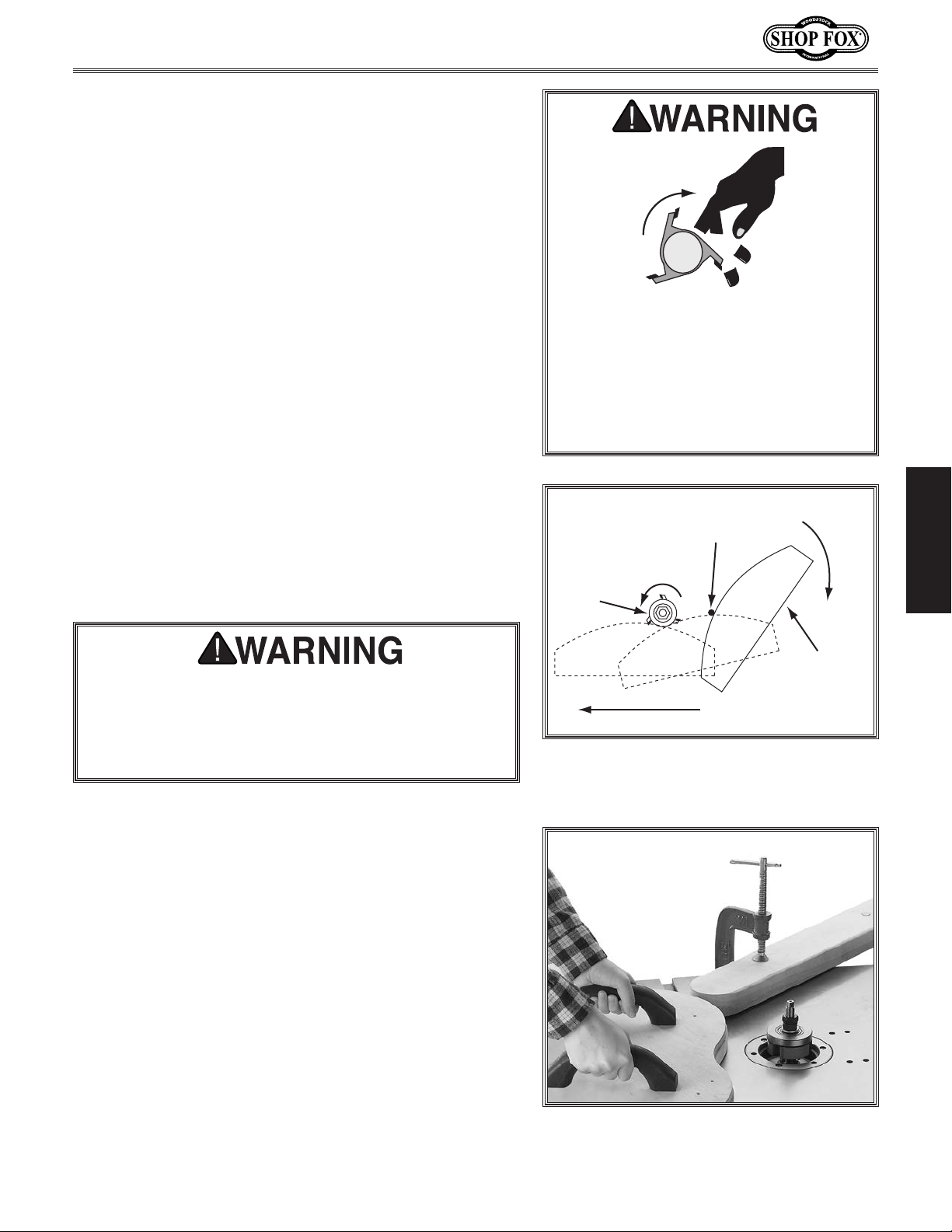
Irregular or freehand routing, as illustrated in Figure 24,
takes a high degree of skill and dexterity and is done
without the protection and aid from the fence and guard.
The most dangerous part of free-hand routing is beginning
the cut, where the cutter first contacts the workpiece.
Often the workpiece will tend to jerk or kickback,
presenting an injury hazard to the operator.
To reduce this tendency, use a starting pin or block (see
Figures 24–25). This will allow you to anchor and slowly
pivot the workpiece into the cutter as the cut is started,
making the operation more stable and safe.
With the fence assembly removed, you MUST use a router
bit with a rub collar to guide the workpiece through the
cut and limit the depth-of-cut. Also, use a jig or fixture to
hold the workpiece so that your hands can be kept at a
safe distance from the router bit while cutting.
If you are unfamiliar with free-hand routing or shaping,
get assistance from an experienced woodworker, read
books on routing and shaping, and start with a simple
project.
ALWAYS use an auxiliary jig and extreme care when
free-hand routing that requires removal of the fence.
Routing without the fence and the attached guard
greatly increases the risk of accidental contact with
the spinning cutter, causing serious personal injury.
To free-hand route, do these steps:
Free-hand or irregular routing greatly
increases the chance that the operator
may lose control of the workpiece,
which could result in serious personal
injury. Therefore, a starting pin or
block and a custom guard or workpiece
holding jig MUST be used.
Swing
Starting Pin
t
a
i
o
t
n
Rub
Collar
Figure 24. Using a starting pin for
freehand routing (custom guard not shown
o
R
for clarity).
Workpiece
Feed Direction
OPERATIONS
1. DISCONNECT ROUTER FROM POWER!
2. Fabricate a jig to use with the workpiece that will
match the finish shape desired, then attach it to the
workpiece (see Figure 25 for an example).
Note: Make sure any fasteners used will not make
contact with the router bit during the cutting
operation. Glue can be used as an alternative.
-17-
Figure 25. Example of using a jig with a
starting block.
Page 20
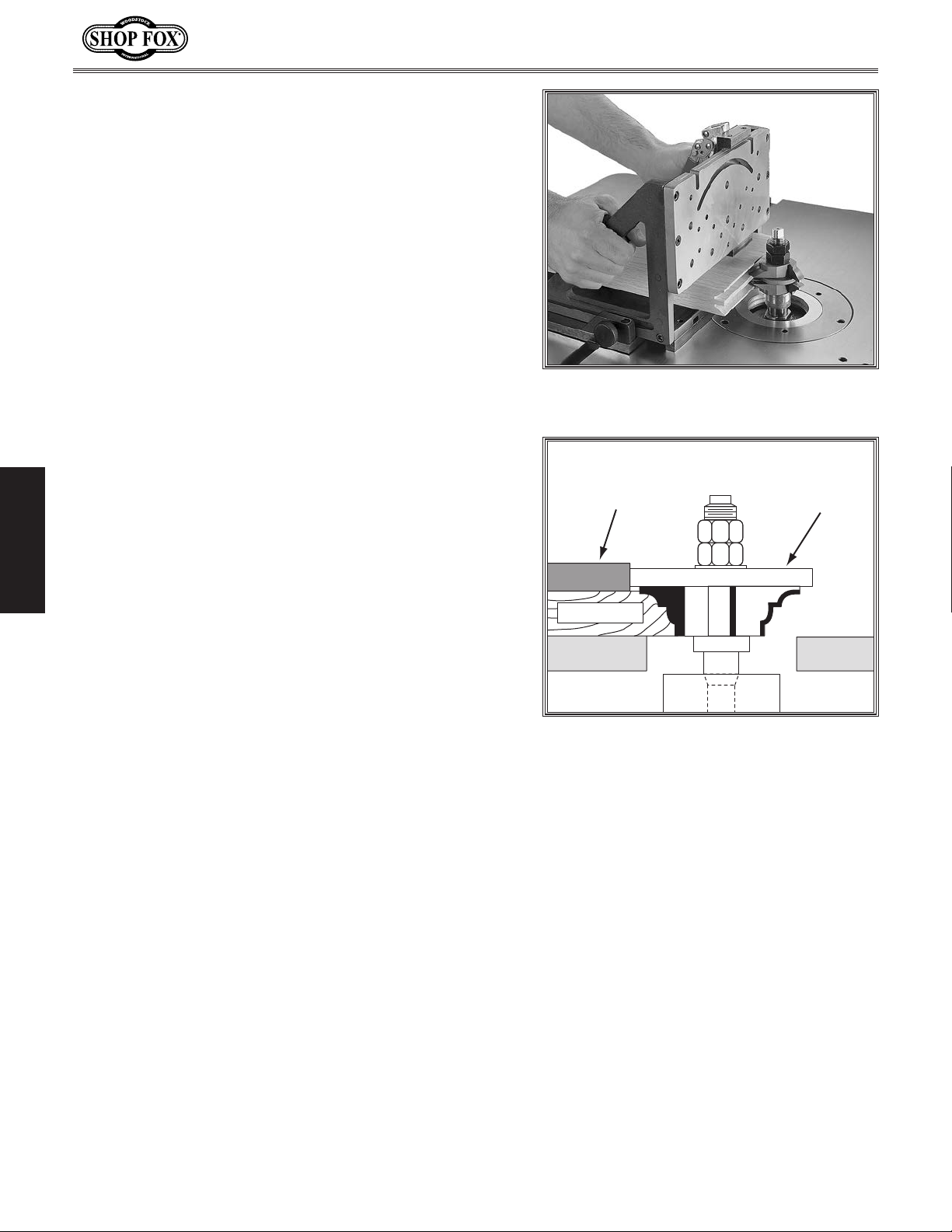
Tip: As an alternative to fabricating a custom jig,
use the Shop Fox Model W1500 Right Angle Jig, as
shown in Figure 26.
3. Remove the fence assembly from the table.
4. Fabricate and mount a custom guard over the bit
that safely protects your hands from the spinning
cutter.
5. Insert the starting pin in the best suited hole on
the routing table or clamp a starting block to the
table (see Figure 25 on the previous page for an
example).
6. Install a router bit with a rub collar as directed by
the router manufacturer's instructions, then raise it
to the desired height (see Figure 27).
Model W1821 (For Machines Mfd. Since 3/16)
Figure 26. Shop Fox Model W1500 Right
Angle Jig.
7. Connect the router to power and turn it ON.
8. Rest the jig with the workpiece attached against the
starting pin or block, then slowly pivot and feed it
into the bit. After the cut is started, move the jig
OPERATIONS
against the rub collar and away from the starting pin
or block, as illustrated in Figure 24 on the previous
page.
Rub
Template
Workpiece
Figure 27. Using a template and a rub
collar for free-hand routing.
Collar
-18-
Page 21
Model W1821 (For Machines Mfd. Since 3/16)
ACCESSORIES
Router Table Attachment Accessories
The following Router Table Attachment accessories may be available through your local Woodstock
International Inc. Dealer. If you do not have a dealer in your area, these products are also available
through online dealers. Please call or e-mail Woodstock International Inc. Customer Service to get a
current listing of dealers at: 1-800-840-8420 or at [email protected].
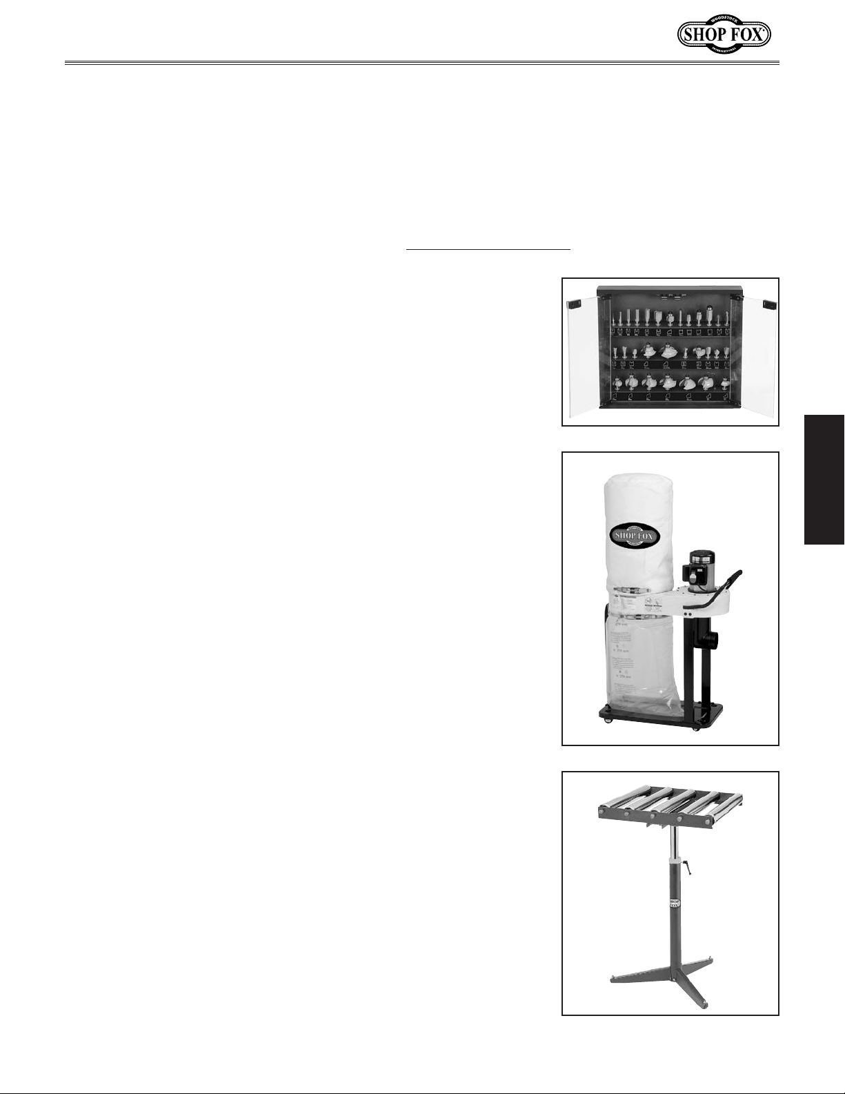
30 Piece Carbide Tipped Router Bit Set
D3726—
D3727—
This 30 piece carbide tipped router bit set includes all of the most
commonly used router bits conveniently labeled and displayed in a
wooden case with see-through, touch-latch doors for easy access.
W1727—Shop Fox 1 HP Dust Collector
Specifications:
• Motor: 1 HP, 110V/220V, single phase, 9/4.5 amp draw
• 800 CFM air suction capacity
• 5.67" of static pressure
• One 4" intake hole
• 9" balanced steel, radial fin impeller
• 2.1 ft
• Base size w/casters: 15
• 2.5 micron bag filtration
• 54
• 59 lbs. approximate shipping weight
1
⁄4" Shank
1
⁄2" Shank
3
bag capacity
1
⁄2" height with bags inflated
3
⁄4" x 39 3⁄4"
OPERATIONS
D2274—Shop Fox 5 Roller Stand
For greater work stability and support, this 5 Roller Stand features
large diameter, ball bearing rollers mounted on a sturdy adjustable
pedestal base. Stand adjusts in height from 26
construction, has 15
capacit y.
7
⁄8" wide ball bearing rollers, and has a 250 lb.
1
⁄2" to 44", is all-steel
-19-
Page 22
MAINTENANCE
General
Regular maintenance on your router table attachment
will ensure its optimum performance. Make a habit of
inspecting your machine each time you use it.
Check for the following conditions and repair or
replace when necessary:
• Loose mounting T-bolts or lock knobs.
• Worn router switch.
• Worn or damaged router cords and plugs.
• Any other condition that could hamper the safe
operation of this router table attachment.
Cleaning & Protecting
Model W1821 (For Machines Mfd. Since 3/16)
MAKE SURE that your router is unplugged
during all maintenance procedures! If
this warning is ignored, serious personal injury may occur.
Frequently blow-off sawdust with compressed air, then
wipe away the remaining dust with a clean shop rag. This
is especially important for the internal working parts of
the fence assembly and the router. Dust build-up around
the router is a sure way to decrease its life span.
The cast-iron router table can be kept rust-free with regular applications of products like SLIPIT
storage you may want to consider products like Boeshield
T-9™.
®
. For long term
MAINTENANCE
-20-
Page 23
Model W1821 (For Machines Mfd. Since 3/16)
PARTS
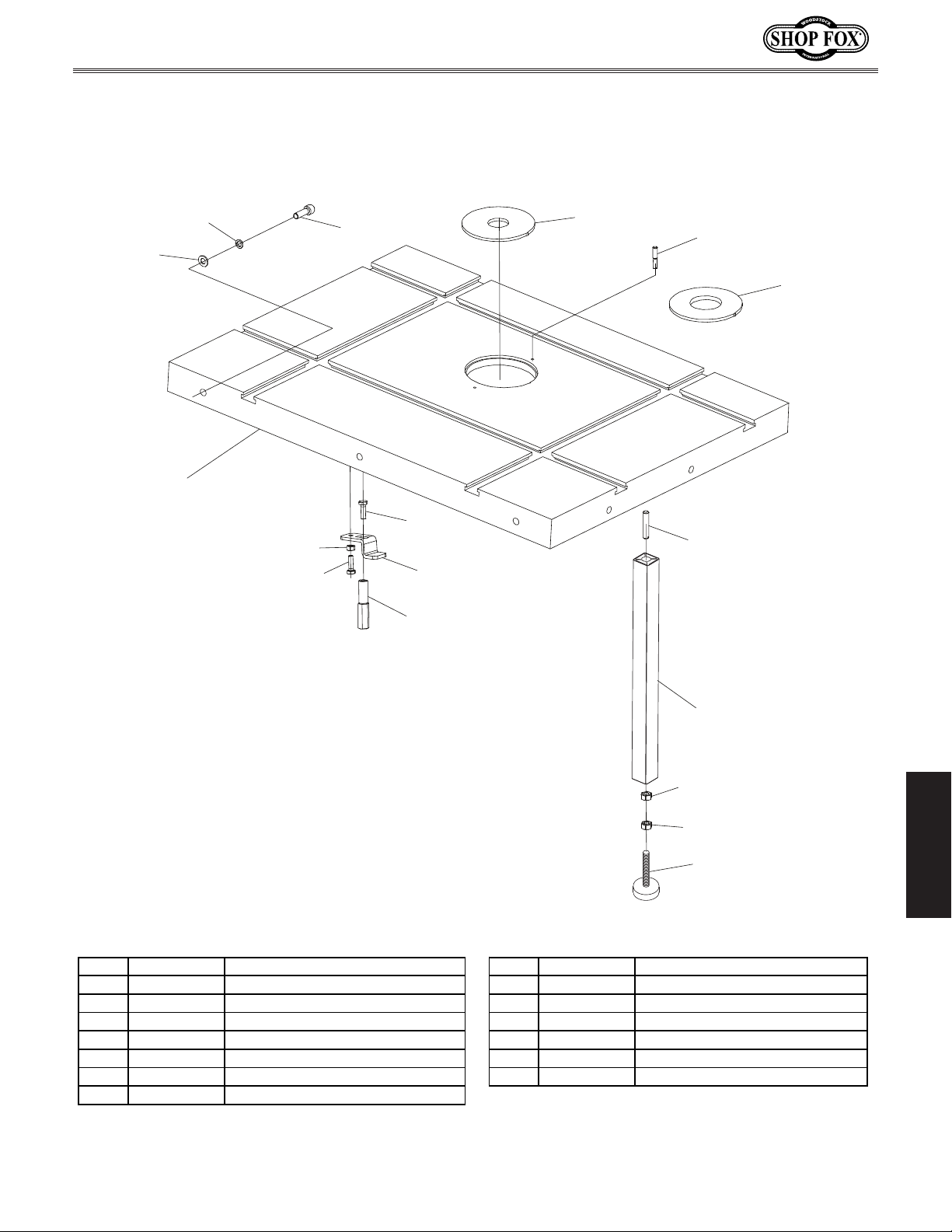
Table
111
101
110
114
115
109
102
116
103
115
104
112
113
105V2
106
106
107V2
REF PART # DESCRIPTION REF PART # DESCRIPTION
101 X1821101 ROUTER TABLE 110 X1821110 LOCK WASHER 8MM
102 X1821102 TABLE INSERT 1" ID 111 X1821111 FLAT WASHER 8MM
103 X1821103 TABLE INSERT 2-3/8" ID 112 X1821112 ROUTER HOLD-DOWN
104 X1821104 THREADED STUD M8-1.25 X 40 113 X1821113 HOLD-DOWN KNOB M6-1
105V2 X1821105V2 SUPPORT LEG (ALUMINUM) V2.03.16 114 X1821114 HEX NUT M6-1
106 X1821106 HEX NUT M8-1.25 115 X1821115 HEX BOLT M6-1 X 20
107V2 X1821107V2 FOOT PAD V2.07.15 116 X1821116 STARTING PIN
109 X1821109 CAP SCREW M8-1.25 X 30
PARTS
-21-
Page 24
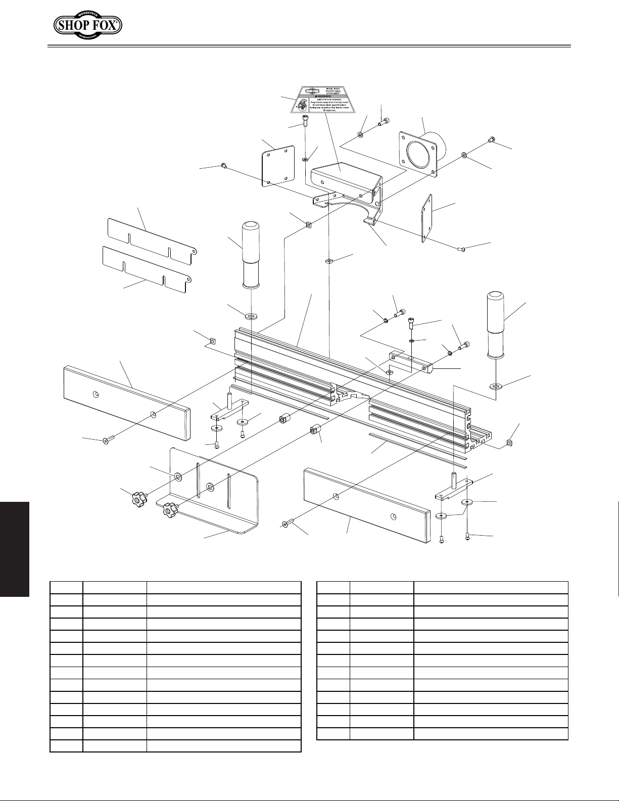
Fence
Model W1821 (For Machines Mfd. Since 3/16)
142
128
129
130
136
120
139
119
143
135
136
134
122
136
133
136
134
135
137
118V2
117V2
133
137
119
121
132V2
134V2
130
120
139
124
125
138
140
139
127
123
138
126
141
128
PARTS
REF PART # DESCRIPTION REF PART # DESCRIPTION
117V2 X1821117V2 DUST PORT 2-1/2" & 3" V2.07.15 132V2 X1821132V2 BUTTON HD CAP SCR M5-.8 X 12
118V2 X1821118V2 DUST HOOD - PLASTIC V2.07.15 133 X1821133 LOCK WASHER 6MM
119 X1821119 DUST HOOD SIDE COVER 134 X1821134 FLAT WASHER 6MM
120 X1821120 KNURLED HANDLE M8-1.25 X 25 134V2 X1821134V2 FLAT WASHER 5MM
121 X1821121 ROUTER GUARD BRACKET 135 X1821135 CAP SCREW M6-1 X 12
122 X1821122 FENCE 136 X1821136 SQUARE NUT M6-1
123 X1821123 PLASTIC ROUTER GUARD 137 X1821137 CAP SCREW M6-1 X 16
124 X1821124 T-SLOT BAR 138 X1821138 FLAT HD SCR M6-1 X 25
125 X1821125 T-SLOT RING 139 X1821139 TEFLON FLAT WASHER 8MM
126 X1821126 GUARD STAND-OFF 140 X1821140 FLAT HD SCR M5-.8 X 8
127 X1821127 STAR KNOB BOLT M6-1 X 15 141 X1821141 PVC PAD
128 X1821128 PHENOLIC FENCE BOARD 142 X1821142 FENCE BOARD SHIM 1.5MM
129 X1821129 FENCE BOARD SHIM 0.7MM 143 X1821143 INJURY HAZARD WARNING LABEL
130 X1821130 BUTTON HD CAP SCR M5-.8 X 12
136
124
125
140
-22-
Page 25

Model W1821 (For Machines Mfg. Since 3/10)
Page 26

FOLD ALONG DOTTED LINE
FOLD ALONG DOTTED LINE
Place
Stamp
Here
Woodstock international inc.
p.o. box 2309
bellingham, Wa 98227-2309
TAPE ALONG EDGES--PLEASE DO NOT STAPLE
Page 27

WARRANTY
WARRANTY
Woodstock International, Inc. warrants all Shop Fox machinery to be free of defects from workmanship
and materials for a period of two years from the date of original purchase by the original owner.
This warranty does not apply to defects due directly or indirectly to misuse, abuse, negligence or
accidents, lack of maintenance, or reimbursement of third party expenses incurred.
Woodstock International, Inc. will repair, replace, or arrange for a dealer refund at its expense and
at its option, the Shop Fox machine or machine part, which in proper and intended use has proven to
be defective, provided that the original owner returns the product prepaid to an authorized warranty
or repair facility as designated by our Bellingham, Washington office with proof of their purchase of
the product within two years, and provides Woodstock International, Inc. reasonable opportunity to
verify the alleged defect through inspection. If it is determined there is no defect, or that the defect
resulted from causes not within the scope of Woodstock International Inc.'s warranty, then the original
owner must bear the cost of storing and returning the product.
This is Woodstock International, Inc.’s sole written warranty and any and all warranties that may be
implied by law, including any merchantability or fitness, for any particular purpose, are hereby limited
to the duration of this written warranty. We do not warrant that Shop Fox machinery complies with
the provisions of any law, acts or electrical codes. We do not reimburse for third party repairs. In no
event shall Woodstock International, Inc.’s liability under this limited warranty exceed the purchase
price paid for the product, and any legal actions brought against Woodstock International, Inc. shall be
tried in the State of Washington, County of Whatcom. We shall in no event be liable for death, injuries
to persons or property or for incidental, contingent, special or consequential damages arising from the
use of our products.
Every effort has been made to ensure that all Shop Fox machinery meets high quality and durability
standards. We reserve the right to change specifications at any time because of our commitment to
Page 28

High Quality Machines and Tools
Woodstock International, Inc. carries thousands of products designed
to meet the needs of today's woodworkers and metalworkers.
Ask your dealer about these fine products:
 Loading...