

Page 1
READ THIS FIRST
177335
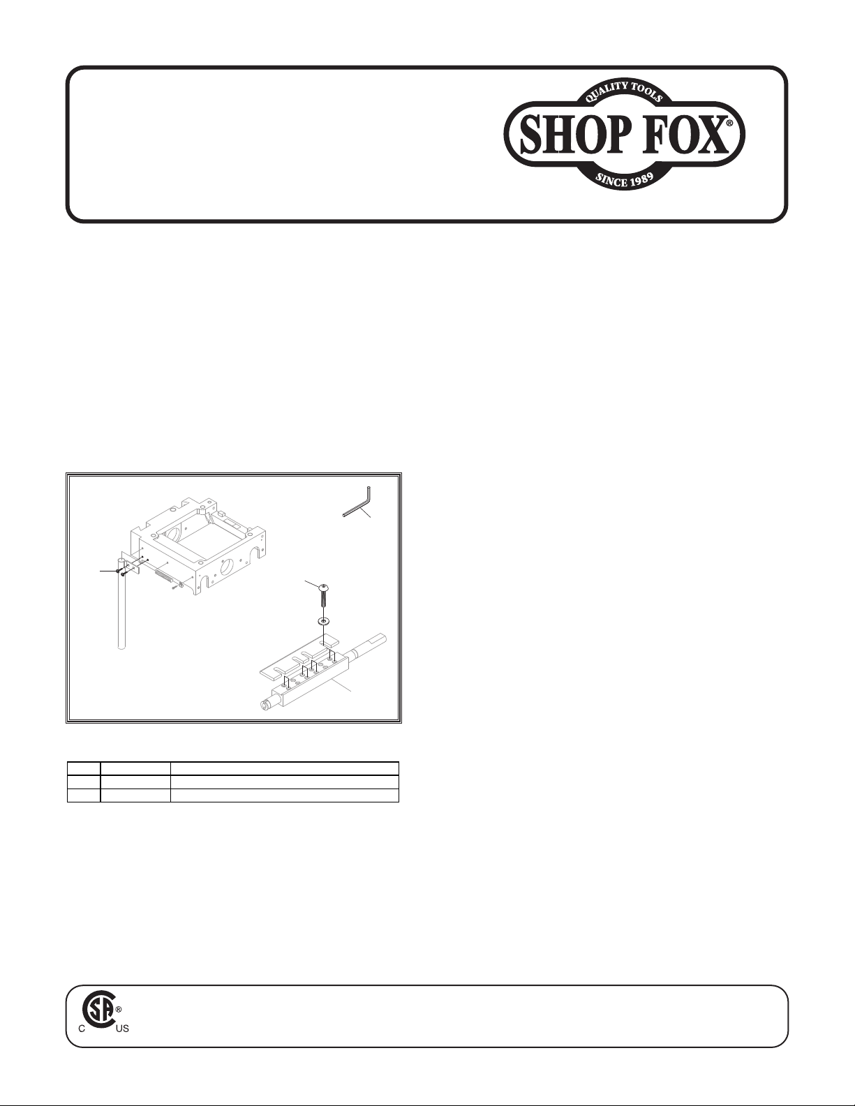
REF PAR T # DESCRIPTION
Model W1812
***IMPORTANT UPDATE***
Applies to Models Mfd. Since 07/22
and Owner's Manual Revised 10/17
Phone #: (360) 647-0802 • Tech Support: [email protected] • Web: www.shopfoxtools.com
The following changes were recently made since the owner's manual was printed:
• Parts changed.
• Inventory and Assembly changed.
Aside from the information contained in this update, all other content in the owner's manual is
applicable and MUST be read and understood for your own safety.
IMPORTANT: Keep this update with the owner's manual for future reference. If you have any further
questions, contact our Technical Support.
Revised Parts
306
71V2 X 1812071V2 BUTT ON H D CA P S CR 3/8-16 X 1 V2. 07.22
254 X 1812254 HEX W R ENCH 6MM
306 X 1812306 FLANGE S CREW 10- 24 X 3/8
71V2
26
254
Revised Box Inventory Qty
J. Hardware Bag ...................................1
— Hex Bolts 5⁄16"-18 x 3⁄4" (Head) ............4
— Flat Washers 5⁄16" (Head) ...................4
— Hex Bolts 5⁄16"-18 x 1" (Pedestal) .......... 3
— Flat Washers 5⁄16" (Pedestal) ...............3
— Flange Screws #10-24 x 3⁄8" (Conduit) .... 2
— Flange Screws #10-24 x 1⁄2" (Dust Port) ..3
— Hex Bolts 5⁄16"-18 x 3⁄4" (Belt Guard) .....2
— Flat Washers 5⁄16" (Drive Belt Guard) ..... 4
— Hex Nuts 5⁄16"-18 (Drive Belt Guard) ...... 2
— Lock Levers 1⁄4"-20 x 3⁄8" (Guide Rail) .... 4
— T-Slot Nuts 1⁄4"-20 (Guide Rail) ............4
— Feet (Stand) ..................................4
— Hex Nuts 3⁄8" x 16 (Feet) ...................8
— Hex Bolts 3⁄8" x 16 x 11⁄4" (Feet) ..........4
— Hex Wrenches 3⁄32", 4, 5, 6mm ....... 1 Ea.
— Open-End Wrench 12/14mm ...............1
Revised Assembly
The following step replaces Step 14 of Assembly
on Page 15 of the owner's manual.
14. Fasten conduit mounting bracket (see
Figure 15) to headstock using (2) #10-24 x
3
⁄8" flange screws.
COPYRIGHT © FEBRUARY, 2024 BY GRIZZLY INDUSTRIAL, INC.
WARNING: NO PORTION OF THIS MANUAL MAY BE REPRODUCED IN ANY SHAPE OR FORM WITHOUT
THE WRITTEN APPROVAL OF GRIZZLY INDUSTRIAL, INC.
Printed in Taiwan#23119KS
Page 2

MODEL W1812
VARIABLE SPEED PLANER/
MOULDER WITH STAND
OWNER'S MANUAL
(FOR MODELS MANUFACTURED SINCE 02/11)
Phone: (360) 734-3482 • Online Technical Support: [email protected]
COPYRIGHT © MARCH, 2009 BY WOODSTOCK INTERNATIONAL, INC. REVISED OCTOBER, 2017 (HE)
WARNING: NO PORTION OF THIS MANUAL MAY BE REPRODUCED IN ANY SHAPE OR FORM WITHOUT
THE WRITTEN APPROVAL OF WOODSTOCK INTERNATIONAL, INC.
177335
#11399CR Printed in Taiwan
Page 3
This manual provides critical safety instructions on the proper setup,
operation, maintenance, and service of this machine/tool. Save this
document, refer to it often, and use it to instruct other operators.
Failure to read, understand and follow the instructions in this manual
may result in fire or serious personal injury—including amputation,
electrocution, or death.
The owner of this machine/tool is solely responsible for its safe use.
This responsibility includes but is not limited to proper installation in
a safe environment, personnel training and usage authorization,
proper inspection and maintenance, manual availability and comprehension, application of safety devices, cutting/sanding/grinding tool
integrity, and the usage of personal protective equipment.
The manufacturer will not be held liable for injury or property
damage from negligence, improper training, machine modifications or
misuse.
Some dust created by power sanding, sawing, grinding, drilling, and
other construction activities contains chemicals known to the State of
California to cause cancer, birth defects or other reproductive harm.
Some examples of these chemicals are:
• Lead from lead-based paints.
• Crystalline silica from bricks, cement and other masonry products.
• Arsenic and chromium from chemically-treated lumber.
Your risk from these exposures varies, depending on how often you
do this type of work. To reduce your exposure to these chemicals:
Work in a well ventilated area, and work with approved safety equipment, such as those dust masks that are specially designed to filter
out microscopic particles.
Page 4

Contents
INTRODUCTION .....................................2
Woodstock Technical Support .................. 2
Controls & Features ............................. 2
Machine Specifications .......................... 3
SAFETY ............................................... 5
Standard Machinery Safety Instructions ...... 5
Additional Safety for Planer/Moulders ....... 7
ELECTRICAL .........................................8
Circuit Requirements ............................8
Grounding Requirements ........................ 9
Extension Cords .................................. 9
SETUP .............................................. 10
Unpacking ....................................... 10
Inventory ........................................ 10
Machine Placement ............................ 11
Cleaning Machine ............................... 11
Lifting & Moving ................................ 12
Mounting Options ............................... 12
Assembly ......................................... 13
Dust Collection ................................. 16
Test Run .......................................... 17
OPERATIONS....................................... 18
General .......................................... 18
Locking Power Switch ......................... 18
Installing Planing Knives ...................... 19
Installing Moulding Knives .................... 20
Feed Roller Height & Spring Tension ........ 21
Workpiece Inspection ......................... 23
Planing Do's & Don'ts .......................... 24
Planing Operation .............................. 25
Moulding Do's & Don'ts ........................ 26
Moulding Operation ............................ 30
ACCESSORIES ...................................... 31
MAINTENANCE .................................... 33
General .......................................... 33
Cleaning ......................................... 33
Cleaning Feed Motor ........................... 33
Table & Base .................................... 33
Lubrication ...................................... 34
SERVICE ............................................ 35
General .......................................... 35
Changing Feed Motor Brushes ................ 35
Feed Roller-to-Table Alignment .............. 36
Drive Chain Adjustment ....................... 37
Gib Adjustment ................................. 38
Electrical Safety Instructions ................. 39
Wiring Diagram ................................. 40
Electrical Component Locations ............. 41
Troubleshooting ................................. 42
PARTS .............................................. 45
Headstock ....................................... 45
Headstock Parts List ........................... 46
Main Motor & Cabinet ......................... 47
Feed Motor & Controls ........................ 48
Feed Motor & Controls Parts List ............ 49
Label Placement ............................... 50
WARRANTY ........................................ 53
SAFETYINTRODUCTION
SET UPELECTRICAL MAINTENANCE
OPERATIONS
USE THE QUICK GUIDE PAGE LABELS TO SEARCH OUT INFORMATION FAST!
SERVICE PARTS
Page 5
W1812 Owner's Manual (Mfd. Since 02/11)
INTRODUCTION
INTRODUCTION
Woodstock Technical Support
This machine has been specially designed to provide many years of trouble-free service. Close attention
to detail, ruggedly built parts and a rigid quality control program assure safe and reliable operation.
Woodstock International, Inc. is committed to customer satisfaction. Our intent with this manual is to
include the basic information for safety, setup, operation, maintenance, and service of this product.
We stand behind our machines! In the event that questions arise about your machine, please contact
Woodstock International Technical Support at (360) 734-3482 or send e-mail to: tech-support@shopfox.
biz. Our knowledgeable staff will help you troubleshoot problems and process warranty claims.
If you need the latest edition of this manual, you can download it from http://www.shopfox.biz.
If you have comments about this manual, please contact us at:
Woodstock International, Inc.
Attn: Technical Documentation Manager
P.O. Box 2309
Bellingham, WA 98227
Email: [email protected]
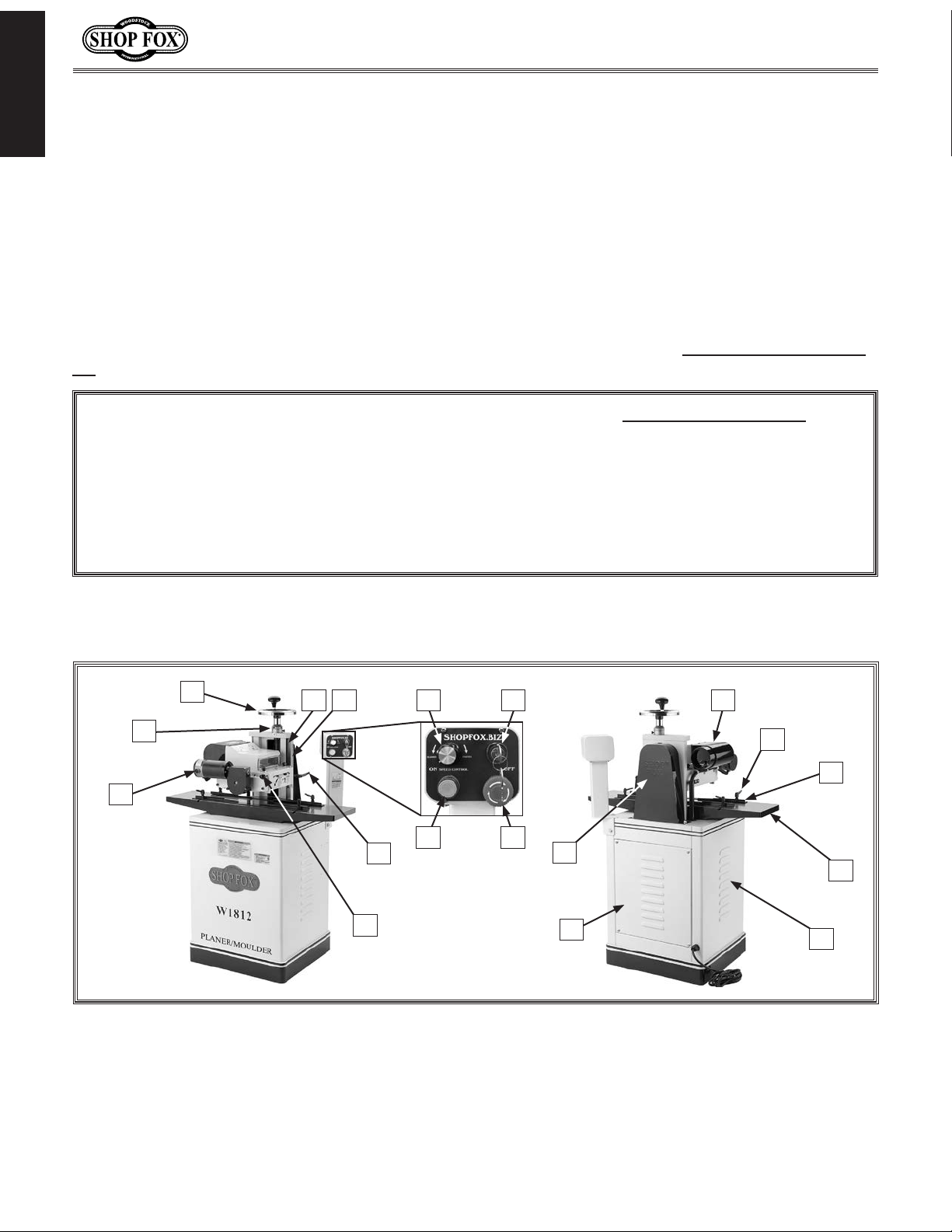
Controls & Features
C
B
A
A. Feed Motor
B. Handwheel Scale
C. Headstock Height Handwheel
D. Dovetailed Column
E. Headstock Scale
F. Feed Speed Control Dial
D G
E
J
K
W1812 Controls & Features.
G. Keyed Power Switch
H. OFF Button
I. Cutterhead ON Button
J. Headstock Lock Lever
K. Chip Deflector Lock Pin
L. Rear Panel
F
I H
N
O
P
M
Q
L
M. Belt guard
N. Dust Cover w/Port
O. Guide Rail Lock Lever
P. Guide Rail Set
Q. Cast Iron Table and Wings
R. Vented Sheet Metal Stand
R
-2-
Page 6

W1812 Owner's Manual (Mfd. Since 02/11)
Machine Specifications
MACHINE
SPECIFICATIONS
Phone #: (360) 734-3482 • Online Tech Support: [email protected] • Web: www.shopfox.biz
MODEL W1812 SHOP FOX
VARIABLE SPEED PLANER/MOULDER WITH STAND
Overall Dimensions
Weight .................................................................................................................. 306 lbs.
Length ...................................................................................................................36
Width .......................................................................................................................22 in.
Height ...................................................................................................................34
Foot Print (Length x Width) ......................................................................................21" x 19 in.
1
⁄4 in.
1
⁄2 in.
INTRODUCTION
Shipping Dimensions
Total Shipping Weight ................................................................................................. 324 lbs.
Box 1 Length x Width x Height ....................................................................40
Box 1 Weight ........................................................................................................... 185 lbs.
Box 2 Length x Width x Height .................................................................... 22
Box 2 Weight ........................................................................................................... 139 lbs.
Electrical
Switch ................................................................. Magnetic Switch w/Thermal Overload Protection
Switch Voltage .............................................................................................................240V
Cord Length ................................................................................................................. 6 ft.
Cord Gauge ..............................................................................................................14 AWG
Recommended Breaker Size ............................................................................................... 15A
Plug Included ....................................................................................................... NEMA 6-15
Motors
Cutterhead
Type ................................................................................... TEFC Capacitor Start Induction
Horsepower .......................................................................................................... 2 HP
Voltage ................................................................................................................ 240V
Phase ................................................................................................................ Single
Amps ................................................................................................................. 10.8A
Speed ............................................................................................................ 3450 RPM
Cycle ................................................................................................................. 60 Hz
Number Of Speeds ...................................................................................................... 1
Power Transfer ...................................................................................... Power Twist V-Belt
Bearings ....................................................................................... Shielded and Lubricated
1
⁄8 x 193⁄4 x 221⁄8 in.
7
⁄8 x 211⁄4 x 301⁄4 in.
Feed Rollers
Type ......................................................................................................... DC Universal
Horsepower ........................................................................................................
Voltage, Amps ............................................................................................. 180VDC, 1.2A
Motor Speed ....................................................................... 0-55 RPM (w/(Voltage Reduction)
Feed Speed ......................................................................................................0-18 FPM
Cycle ................................................................................................................. 60 Hz
Number Of Speeds ......................................................................................Variable Speed
Power Transfer ...............................................................................................Chain Drive
-3-
1
⁄8 HP
Page 7

INTRODUCTION
Main Specifications
Cutting Capacities
Maximum Planing Width ............................................................................................ 7 in.
Maximum Planing Depth ..........................................................................................
Maximum Planing Height ........................................................................................ 7
Maximum Profile Width ......................................................................................... 6
Maximum Profile Depth ...........................................................................................
Minimum Stock Thickness .........................................................................................
Minimum Stock Length ............................................................................................. 9 in.
Knife Information
Number of Knives ....................................................................................................... 2
Knife Type ............................................................................................................. HSS
Knife Length ...................................................................................................... 7
Knife Width ........................................................................................................ 1
Knife Thickness .....................................................................................................
Number of Cuts Per Minute ......................................................................................14,000
Number of Cuts Per Inch .........................................................................................64-300
Cutterhead Information
Cutterhead Type .................................................................................................. Square
Cutterhead Diameter ............................................................................................ 1
Cutterhead Speed ............................................................................................. 7000 RPM
W1812 Owner's Manual (Mfd. Since 02/11)
1
⁄8 in.
1
⁄2 in.
3
⁄4 in.
3
⁄4 in.
1
⁄4 in.
1
⁄8 in.
1
⁄2 in.
1
⁄4 in.
1
⁄4 in.
Table Information
Table Length w/Wings ..........................................................................................36
Table Length w/o Wings........................................................................................14
Table Width .........................................................................................................10 in.
Table Thickness ....................................................................................................
Extension Wing Length ............................................................................................11 in.
Extension Wing Width .......................................................................................... 8
Floor to Table Height ...........................................................................................30
Other Information
Number of Dust Ports ................................................................................................... 1
Dust Port Size ........................................................................................................ 4 in.
Measurement Scale Units ........................................................................................ Inches
Construction Materials
Cabinet ........................................................................................................... Formed Steel
Body Assembly .........................................................................................................Cast Iron
Cutterhead Assembly ......................................................................................................Steel
Table & Extension Wing ........................................................................ Precision Ground Cast Iron
Paint ............................................................................................................... Powder Coat
Infeed and Outfeed Rollers ...........................................................................Rubber Coated Steel
Other
Country of Origin ....................................................................................................... Taiwan
Warranty .................................................................................................................. 2 Year
Approximate Assembly Time ......................................................................................45 Minutes
Serial Number Location .................................................................................... Machine ID Label
Certified by a Nationally Recognized Testing Laboratory (NRTL) .................................................... Ye s
1
⁄4 in.
1
⁄8 in.
7
⁄16 in.
9
⁄16 in.
3
⁄8 in.
Features
Heavy-Duty Cast Iron Handwheel with Inch Measurement Scale for Cutterhead Housing Lift
Precision-Ground Cast Iron Infeed and Outfeed Extension Wings
Dovetailed Way for Cutterhead Housing with Precision Gib Adjustments
Pedestal-Mounted Control Switch with Variable Speed Control
-4-
Page 8

W1812 Owner's Manual (Mfd. Since 02/11)
SAFETY
OWNER’S
EYE PROTECTION.
HAZARDOUS
WEARING PROPER APPAREL.
of workpiece control.
disconnect machine from power supply before
is in OFF position before reconnecting to avoid
manual uses a series of symbols and signal words intended to convey the level of importance of the
safety messages. The progression of symbols is described below. Remember that safety messages by
-
For Your Own Safety,
SAFETY
Read Manual Before Operating Machine
The purpose of safety symbols is to attract your attention to possible hazardous conditions. This
themselves do not eliminate danger and are not a substitute for proper accident prevention mea
sures—this responsibility is ultimately up to the operator!
NOTICE
Standard Machinery Safety Instructions
Standard Machinery Safety Instructions
Indicates an imminently hazardous situation which, if not avoided,
WILL result in death or serious injury.
Indicates a potentially hazardous situation which, if not avoided,
COULD result in death or serious injury.
Indicates a potentially hazardous situation which, if not avoided,
MAY result in minor or moderate injury.
This symbol is used to alert the user to useful information about
proper operation of the equipment, and/or a situation that may
cause damage to the machinery.
SAFETY
MANUAL. Read and understand this
owner’s manual BEFORE using machine.
Untrained users can be seriously hurt.
safety glasses or a face shield when operating
or observing machinery to reduce the risk of
eye injury or blindness from flying particles.
Everyday eyeglasses are not approved safety
glasses.
DUST. Dust created while using
machinery may cause cancer, birth defects,
or long-term respiratory damage. Be aware
of dust hazards associated with workpiece
materials, and always wear a NIOSH-approved
respirator to reduce your risk.
clothing, apparel, or jewelry that can become
entangled in moving parts. Always tie back
or cover long hair. Wear non-slip footwear to
avoid accidental slips which could cause a loss
Always wear ANSI-approved
Do not wear
HEARING PROTECTION. Always wear hearing
protection when operating or observing
loud machinery. Extended exposure to this
noise without hearing protection can cause
permanent hearing loss.
MENTAL ALERTNESS. Be mentally alert when
running machinery. Never operate under the
influence of drugs or alcohol, when tired, or
when distracted.
DISCONNECTING POWER SUPPLY. Always
servicing, adjusting, or changing cutting tools
(bits, blades, cutters, etc.). Make sure switch
an unexpected or unintentional start.
DANGEROUS ENVIRONMENTS. Do not use
machinery in wet or rainy locations, cluttered
areas, around flammables, or in poorly-lit
areas. Keep work area clean, dry, and welllighted to minimize risk of injury.
-5-
Page 9

W1812 Owner's Manual (Mfd. Since 02/11)
APPROVED OPERATION. Untrained operators
ONLY USE AS INTENDED
USE RECOMMENDED ACCESSORIES
CHILDREN & BYSTANDERS.
REMOV
SECURING WORKPIECE.
FEED DIRECTION.
GUARDS & COVERS.
NEVER STAND ON MACHINE.
STABLE MACHINE. Unexpected movement during
will do the job safer and better at the rate for
positions that make workpiece control difficult
can be seriously hurt by machinery. Only
allow trained or properly supervised people
to use machine. When machine is not being
used, disconnect power, remove switch keys,
or lock-out machine to prevent unauthorized
use—especially around children. Make
workshop kid proof!
SAFETY
. Only use machine for
its intended purpose. Never modify or alter
machine for a purpose not intended by the
manufacturer or serious injury may result!
. Consult
this owner’s manual or the manufacturer for
recommended accessories. Using improper
accessories will increase the risk of serious
injury.
Keep children and
bystanders a safe distance away from work
area. Stop using machine if children or
bystanders become a distraction.
E ADJUSTING TOOLS. Never leave
adjustment tools, chuck keys, wrenches, etc.
in or on machine—especially near moving
parts. Verify removal before starting!
When required, use
clamps or vises to secure workpiece. A secured
workpiece protects hands and frees both of
them to operate the machine.
operations greatly increases the risk of injury
and loss of control. Verify machines are
stable/secure and mobile bases (if used) are
locked before starting.
FORCING MACHINERY. Do not force machine. It
which it was designed.
AWKWARD POSITIONS. Keep proper footing and
balance at all times when operating machine.
Do not overreach! Avoid awkward hand
or increase the risk of accidental injury.
UNATTENDED OPERATION. Never leave machine
running while unattended. Turn machine off
and ensure all moving parts completely stop
before walking away.
MAINTAIN WITH CARE. Follow all maintenance
instructions and lubrication schedules to
keep machine in good working condition. An
improperly maintained machine may increase
the risk of serious injury.
CHECK DAMAGED PARTS. Regularly inspect
machine for damaged parts, loose bolts,
mis-adjusted or mis-aligned parts, binding,
or any other conditions that may affect safe
operation. Always repair or replace damaged
parts, wires, cords, or plugs before operating
machine.
Unless otherwise noted, feed
work against the rotation of blades or cutters.
Feeding in the same direction of rotation may
pull your hand into the cut.
protect you from accidental contact with
moving parts or flying debris. Make sure
they are properly installed, undamaged, and
working correctly before using machine.
accidental contact with cutting tool may
occur if machine is tipped. Machine may be
damaged.
Guards and covers can
Serious injury or
MAINTAIN POWER CORDS. When disconnecting
cord-connected machines from power, grab
and pull the plug—NOT the cord. Pulling the
cord may damage the wires inside. Do not
handle the cord/plug with wet hands. Avoid
cord damage by keeping it away from heated
surfaces, high traffic areas, harsh chemicals,
and wet or damp locations.
EXPERIENCING DIFFICULTIES. If at any time you
are experiencing difficulties performing the
intended operation, stop using the machine!
Contact our Technical Support for help at
(360) 734-3482.
-6-
Page 10
W1812 Owner's Manual (Mfd. Since 02/11)
Additional Safety for Planer/Moulders
READ and understand this
entire manual before using
this machine. Serious personal injury may occur
if safety and operational
information is not understood and followed. DO
NOT risk your safety by
not reading!
REACHING INSIDE PLANER/MOULDER. Never
reach inside planer/moulder or remove covers
when the planer/moulder is connected to
po wer.
INFEED CLEARANCE SAFETY. The infeed roller is
designed to pull material into the cutterhead.
Always keep hands, clothing, and long hair
away from the infeed roller during operation
to prevent serious injury.
PLANING CORRECT MATERIAL. Only plane natural
wood stock with this planer/moulder. DO
NOT plane MDF, plywood, laminates, or other
synthetic products.
WORKPIECE CLEARANCE. Always verify workpiece
has enough room to exit the planer before
starting.
REMOVING JAMMED WORKPIECES. To avoid
serious injury, always stop the planer/moulder
and disconnect power before removing
jammed workpieces.
DULL/DAMAGED CUTTERS. The planer/moulder
may kick out a workpiece at the operator or
give poor finish results if it is operated with
dull or damaged knives.
USE this and other machinery with caution
and respect. Always consider safety first,
as it applies to your individual working
conditions. No list of safety guidelines can
be complete—every shop environment is
different. Failure to follow guidelines could
result in serious personal injury, damage
to equipment or poor work results.
GRAIN DIRECTION. Cutting across or against the
grain is hard on the planer/moulder and may
increase the risk of workpiece kick out. Always
cut with the grain or at a slight angle with the
grain.
BODY POSITION WHILE OPERATING. The
workpiece may kick out during operation.
To avoid getting hit, stand to the side of the
planer/moulder during the entire operation.
KNIFE CLEARANCE. Before starting the machine,
always verify that the moulding knives do not
contact any part of the workpiece guide rails,
feed roller swing arm, or the table surface.
Failure to verify knife clearance may result
in severe injury and machine damage!
LOOKING INSIDE PLANER/MOULDER. Wood chips
fly around inside the planer/moulder at a
high rate of speed. DO NOT look inside the
machine or remove any guards or covers during
operation.
UNPLUGGING DURING ADJUSTMENTS. When
connected to power, the planer/moulder can
be accidentally turned ON. Always disconnect
power when servicing or adjusting machine
components.
SAFETY
-7-
Page 11
W1812 Owner's Manual (Mfd. Since 02/11)
This machine must be connected to the correct size and
type of power supply circuit, or fire or electrical damage
may occur. Read through this section to determine if an
adequate power supply circuit is available. If a correct
circuit is not available, a qualified electrician MUST install
one before you can connect the machine to power.
A power supply circuit includes all electrical equipment
between the breaker box or fuse panel in the building
and the machine. The power supply circuit used for
this machine must be sized to safely handle the fullload current drawn from the machine for an extended
period of time. (If this machine is connected to a circuit
protected by fuses, use a time delay fuse marked D.)
This machine is prewired to operate on a power supply
circuit that has a verified ground and meets the following
requirements:
The full-load current rating is the amperage a machine
draws at 100% of the rated output power. On machines
with multiple motors, this is the amperage drawn by the
largest motor or sum of all motors and electrical devices
that might operate at one time during normal operations.
or machine damage. To reduce this risk,
where only one machine will be running
ELECTRICAL
Circuit Requirements
The machine must be properly set up
before it is safe to operate. DO NOT
connect this machine to the power
source until instructed to do later in
this manual.
ELECTRICAL
Full-Load Current Rating
Full-Load Current Rating at 230V .................. 12 A mps
Circuit Requirements for 230V
Circuit Ty pe ......................230V, 60 Hz, Single-Phase
Circuit Size ............................................. 15 Amps
Plug/Receptacle .................................... NEM A 6-15
Incorrectly wiring or grounding this
machine can cause electrocution, fire,
only an electrician or qualified service
personnel should do any required
electrical work on this machine.
NOTICE
The circuit requirements listed in this
manual apply to a dedicated circuit—
at a time. If this machine will be
connected to a shared circuit where
multiple machines will be running at
the same time, consult a qualified
electrician to ensure that the circuit is
properly sized for safe operation.
-8-
Page 12
W1812 Owner's Manual (Mfd. Since 02/11)
This machine MUST be grounded. In the event of certain
types of
a path of least resistance for electric current
order
Improper connection of the equipment-grounding
will
increase
insulation
grounding
cord or plug is necessary, do not connect the equipmentgrounding
Check with a qualified electrician or service personnel
if
or if
properly grounded.
plug is damaged or worn, disconnect it from power, and
immediately replace it with a new one.
the available receptacle, or the machine
We do not recommend using an extension cord with
Any extension cord used with this machine must contain a
plug and receptacle, and
meet the following requirements:
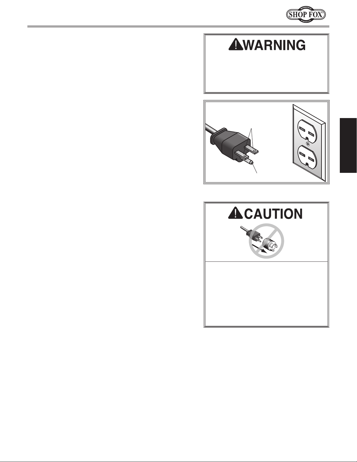
This machine is equipped with a power cord that has an
equipment-grounding
The plug
receptacle
(
accordance with local codes and ordinances.
Grounding Requirements
malfunctions or breakdowns, grounding provides
to travel—in
to reduce the risk of electric shock.
wire
the risk of electric shock. The wire with green
(with/without yellow stripes) is the equipment-
wire. If repair or replacement of the power
wire to a live (current carrying) terminal.
you do not understand these grounding requirements,
you are in doubt about whether the tool is
If you ever notice that a cord or
wire and NE M A 6-15 grounding plug.
must only be inserted into a matching
see Figure) that is properly installed and grounded in
The machine must be properly set up
before it is safe to operate. DO NOT
connect this machine to the power
source until instructed to do later in
this manual.
220V
Current Carrying Prongs
6-15 PLUG
Figure 1. NEMA 6-15 plug & receptacle.
GROUNDED
6-15 RECEPTACLE
Grounding Prong
ELECTRICAL
Extension Cords
this machine. Extension cords cause voltage drop, which
may damage electrical components and shorten motor
life. Voltage drop increases with longer extension cords
and smaller gauge sizes (higher gauge numbers indicate
smaller sizes).
ground wire
Minimum Gauge Size at 230V ...................... 14 AWG
Maximum Length (Shorter is Better) ................ 50 ft.
, match the required
No adapter should be used with the
required plug. If the plug does not fit
must be reconnected to a different
type of circuit, the reconnection must
be made by an electrician or qualified
service personnel and it must comply
with all local codes and ordinances.
-9-
Page 13
SETUP
Unpacking
This machine has been carefully packaged for safe
transportation. If you notice the machine has been
damaged during shipping, please contact your authorized
Shop Fox dealer immediately.
Inventory
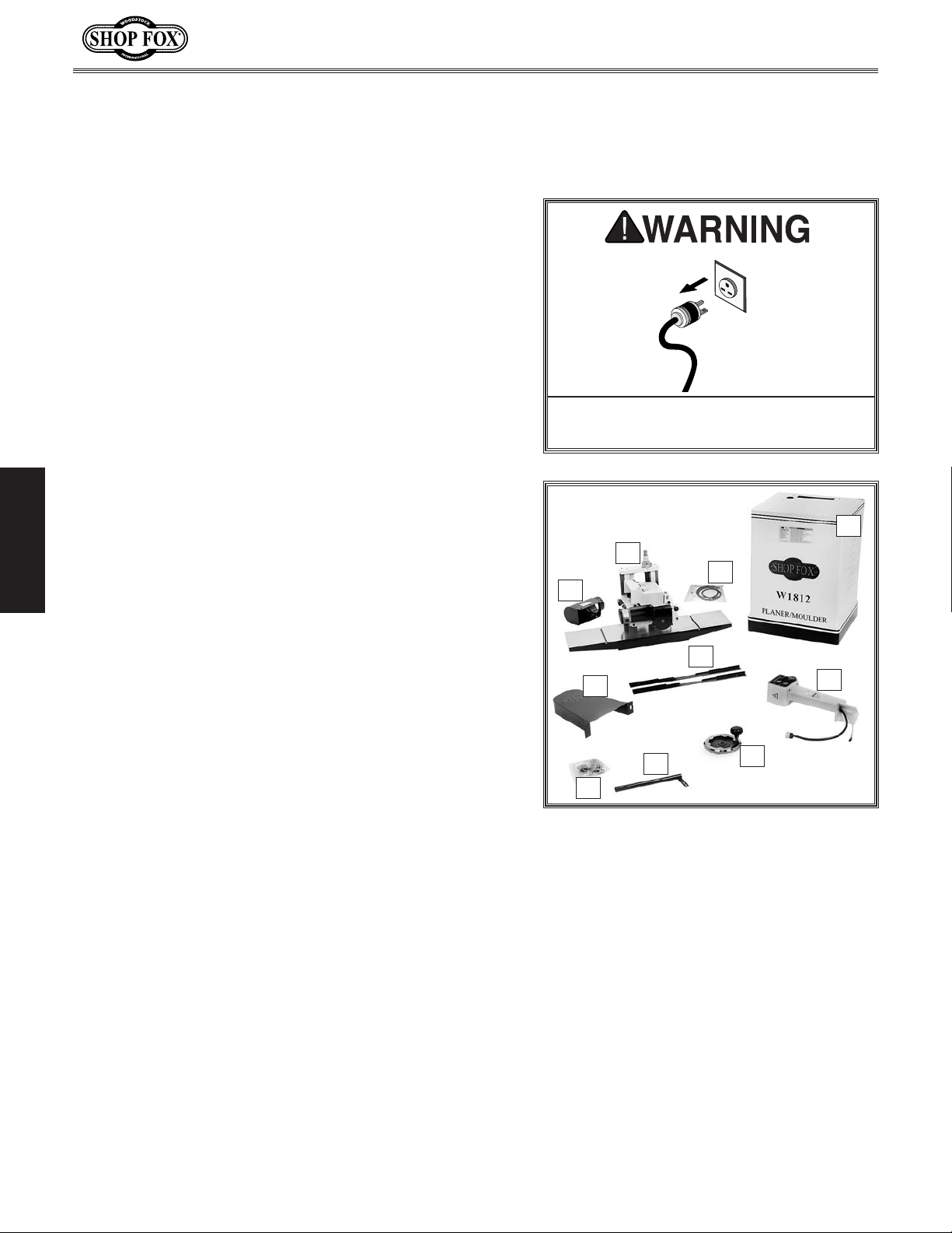
The following is a description of the main components
shipped with the Model W1812. Lay the components out
to inventory them.
Note: If you can't find an item on this list, check the
mounting location on the machine or examine the
packaging materials carefully. Occasionally we pre-install
certain components for safer shipping.
W1812 Owner's Manual (Mfd. Since 02/11)
Keep machine disconnected from
power until instructed otherwise.
D
Box Inventory (see Figure 2) Qty
SETUP
A. Dust Hood ...................................................1
B. Planer/Moulder Head/Table Assembly .................1
C. Link Belt ....................................................1
D. Stand ........................................................1
E. Belt Guard ..................................................1
F. Guide Rail Set ..............................................1
G. Pedestal Control Panel ...................................1
H. Handwheel w/Knob .......................................1
I. Steel Conduit ...............................................1
J. Hardware Bag ..............................................1
5
— Hex Bolts
— Flat Washers
— Hex Bolts
— Flat Washers
— Flange Screws
— Flange Screws #10-24 x
— Hex Bolts
— Flat Washers
— Hex Nuts
— Lock Levers
— T-Slot Nuts
⁄16"-18 x 3⁄4" (Planer/Moulder Head) ...4
5
⁄16" (Planer/Moulder Head) ..........4
5
⁄16"-18 x 1" (Pedestal Control Panel) ...3
5
⁄16" (Pedestal Control Panel) ........3
5
⁄16"-18 x 3⁄8" (Steel Conduit) .......2
5
⁄16"-18 x 3⁄4" (Belt Guard) ................2
5
⁄16" (Drive Belt guard) ................4
5
⁄16"-18 (Drive Belt guard) .................2
1
⁄4"-20 x 3⁄8" (Guide Rail) ...............4
1
⁄4"-20 (Guide Rail) .......................4
1
⁄2" (Dust Port Support) ..3
— Feet (Stand) .............................................4
3
— Hex Nuts
— Hex Bolts
— Hex Wrenches
⁄8" x 16 (Feet) ..............................8
3
⁄8" x 16 x 11⁄4" (Feet) .....................4
3
⁄32", 4, 5mm ......................1 Ea
— Open-End Wrench 12/14mm ..........................1
5
— Depth Stop Hex Bolt
5
— Hex Nut
⁄16"-18 (Depth Stop) .........................1
⁄16"-18 x 1" (Depth Stop) ....1
B
C
A
F
E
I
H
G
J
Figure 2. Inventory.
-10-
Page 14
W1812 Owner's Manual (Mfd. Since 02/11)
Machine Placement
• Floor Load: This machine distributes a
heavy load in a small footprint. Some
residential floors may require additional
bracing to support both machine and
operator.
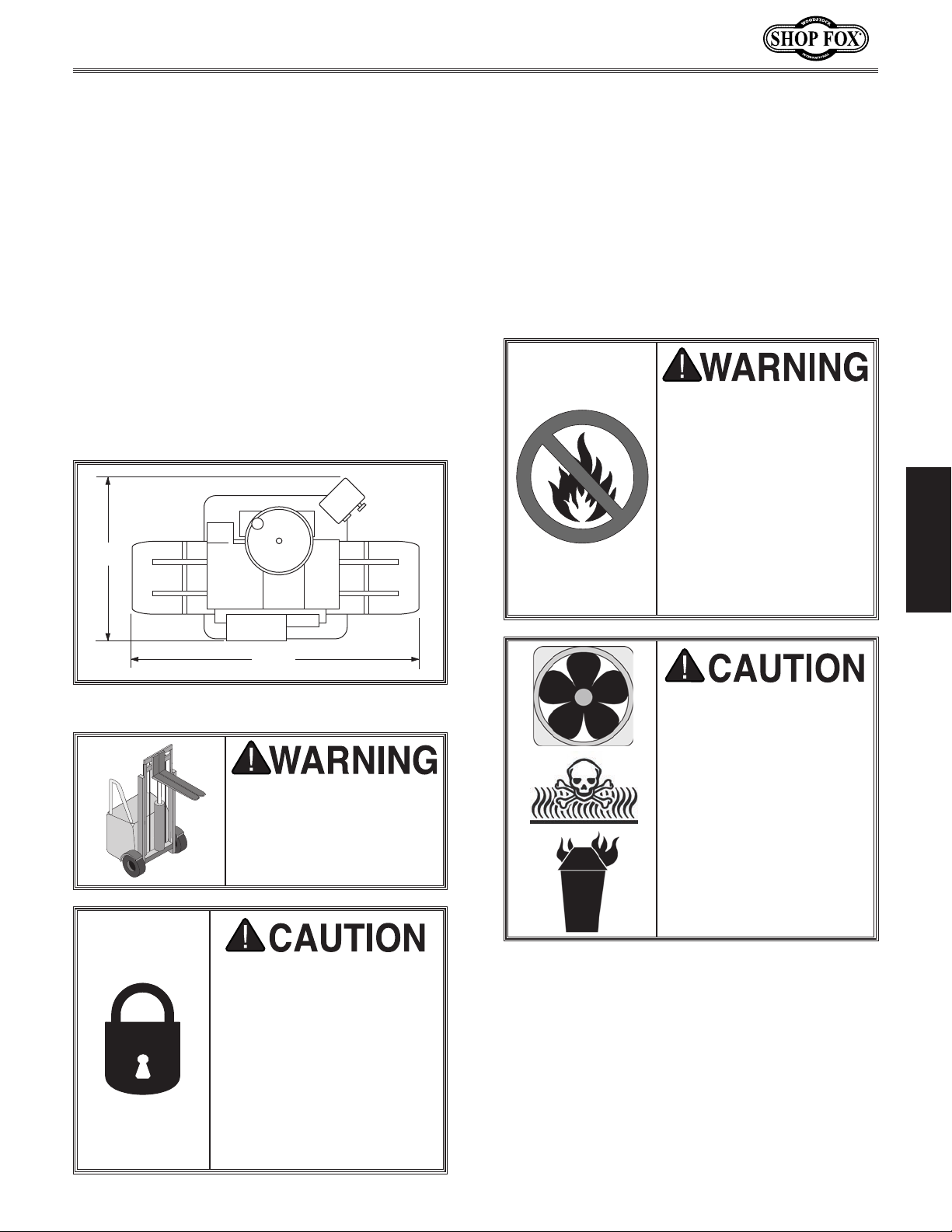
• Working Clearances: Consider existing and
anticipated needs, size of material to be
processed through the machine, and space
for auxiliary stands, work tables or other
machinery when establishing a location for
your planer/moulder.
• Lighting: Lighting should be bright enough
to eliminate shadow and prevent eye strain.
24"
Cleaning Machine
The table and other unpainted parts of your
planer/moulder are coated with a waxy grease
that protects them from corrosion during
shipment. Clean this grease off with a solvent
cleaner or citrus-based degreaser. DO NOT use
chlorine-based solvents such as brake parts
cleaner or acetone—if you happen to splash
some onto a painted surface, you may ruin the
finish.
NEVER clean with gasoline
or other petroleumbased solvents. Most have
low flash points, which
make them extremely
flammable. A risk of
explosion and burning
exists if these products
are used. Serious personal
injury may occur if this
warning is ignored!
SETUP
361/4"
Figure 3. Minimum working clearances.
USE helpers or power
lifting equipment to
lift the planer/moulder.
Otherwise, serious personal injury may occur.
MAKE your shop “child
safe.” Ensure that your
workplace is inaccessible
to children by closing and
locking all entrances when
you are away. NEVER allow
untrained visitors in your
shop when assembling,
adjusting or operating
equipment.
ALWAYS work in wellventilated areas far from
possible ignition sources
when using solvents to
clean machinery. Many
solvents are toxic when
inhaled or ingested. Use
care when disposing
of waste rags and
towels to be sure they
DO NOT create fire or
environmental hazards.
-11-
Page 15
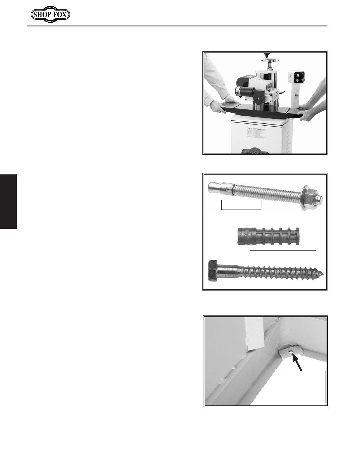
Lifting & Moving
The Model W1812 can be moved short distances if two
people lift the ends of the cast iron extension wings
and walk the machine to the new location. For ease of
mobility, the machine can be placed on a Shop Fox Model
D2057A Heavy Duty Mobile Base.
For long distance moving, we recommend using a forklift
or other mechanical lifting or moving device.
Mounting Options
Before beginning assembly, review the general mounting
options below, while keeping in mind your current and
future machine operation and storage needs. We generally
recommend that most machinery be fastened to the floor
to dampen vibration and provide maximum stability.
However, since floor materials vary, mounting hardware
is not included. Some machinery may find its way into
industrial shops or specialized settings where unique
mounting fasteners and electrical grounding requirements
SETUP
apply. Make sure to follow all necessary codes and
regulations when installing this machine.
W1812 Owner's Manual (Mfd. Since 02/11)
Figure 4. Lifting location.
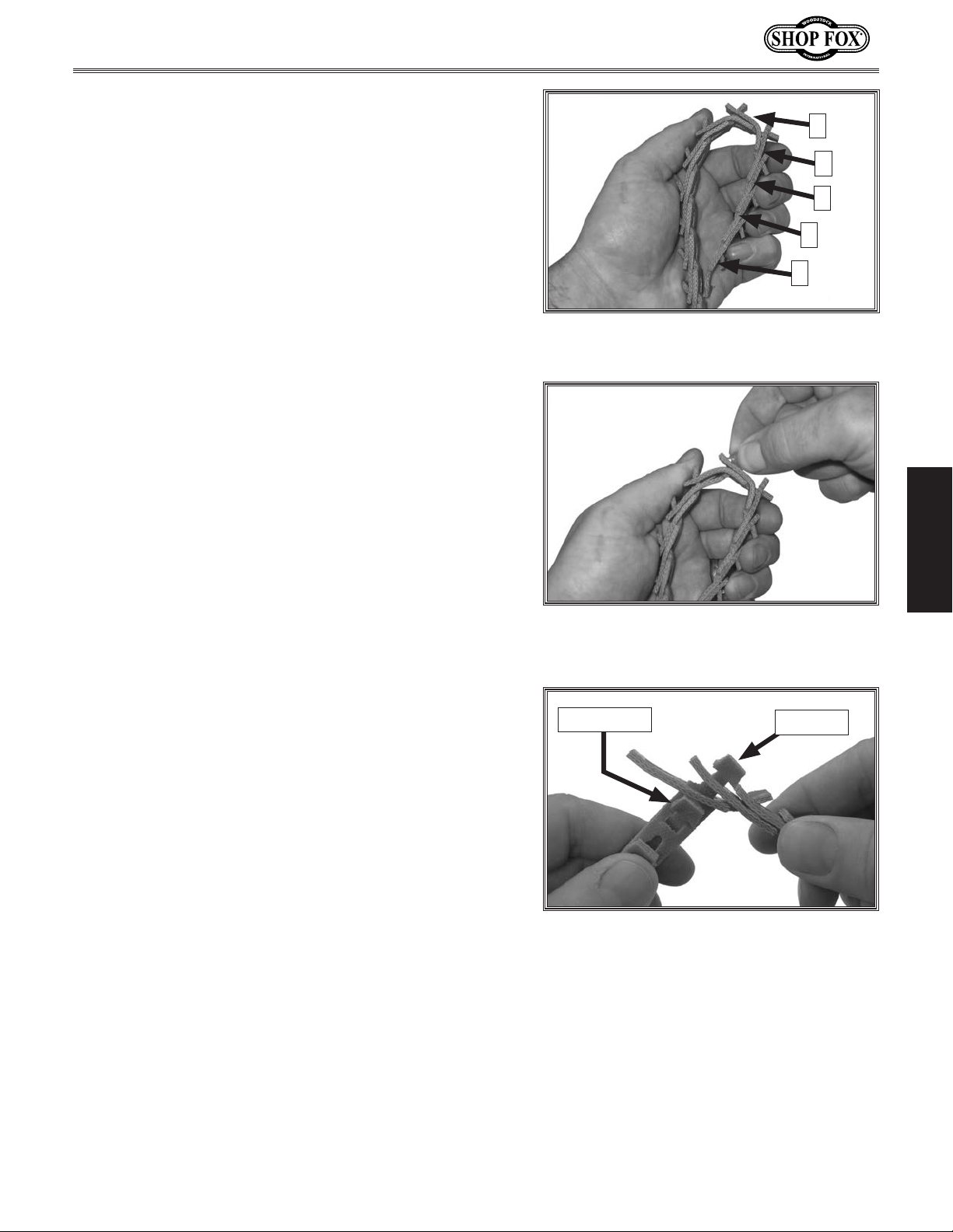
Anchor Stud
Fastening to Floors
If you choose to physically fasten the machine to the
floor, do not install the included rubber feet. With the
Model W1812, the anchor studs or lag screws shown
in Figure 5 will pass through the four
reinforced holes (see Figure 6) that are for the rubber
feet.
Anchor studs are stronger and more permanent
alternatives to lag screws and anchors; however, anchor
studs will stick out of the floor, which may cause a
tripping hazard later if you decide to move your machine.
NEVER use air tools or excessively tighten the fasteners to
level or eliminate the machine from rocking on an uneven
floor. Doing so can bend or twist machine components
and damage the fasteners. Instead add shims between
the machine base and the floor to achieve stability and
alignment before tightening the fasteners by hand.
3
⁄8" diameter
Machine Feet
If you install the rubber feet included with the W1812,
independent foot adjustment for stability will be possible.
The rubber portions of the feet will also help dampen
machine vibration.
Lag Screw and Anchor
Figure 5. Typical fasteners for mounting to
concrete floors.
3
⁄8" Diameter
Reinforced
Mounting
Hole
Figure 6. Foot installation location.
-12-
Page 16
W1812 Owner's Manual (Mfd. Since 02/11)
Assembly
The Model W1812 Planer/Moulder is shipped with an
off-the-shelf 48" Power Twist™ Link V-Belt. The planer/
moulder is designed for a 45" V-belt, so the included
V-belt must be modified before installing it.
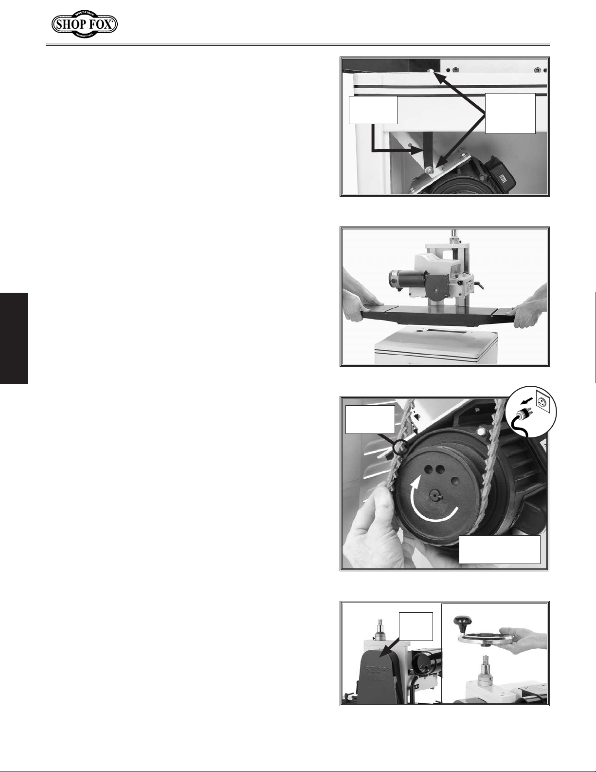
To remove links, do the following:
1. Count 5 links away from the end of the belt, turn
the belt inside out and squeeze it together where
the 5th link connects, as shown in Figure 7.
2. Twist one of the tabs sideways, as shown in
Figure 8, and push it down through the two layers of
links.
Note: If you have difficulty twisting the tab, you
can use pliers, but take care not to over-twist the
tab or you could damage the belt.
3. Repeat Step 2 with the second tab on the link, but
only pulling that tab out of one layer. The section of
5 links are now removed from the belt.
5
4
3
2
1
Figure 7. Bending belt inside-out a the 5th
link.
SETUP
To connect the belt together, do the following steps:
1. Push the first tab on one end of the belt through the
second slot (the one with two layers) on the other
end of the belt, as shown in Figure 9.
2. Rotate the tab-end of the belt 90°, so the tabs point
the same direction as the other tabs on the belt.
3. Bend the belt backwards (similar to Figure 7), twist
the second tab, and push it through the hole.
4. Turn the belt outside-out and install it on the
machine as described in the owner's manual.
To assemble the planer/moulder, do these steps:
3
1. Lay the stand on its side, insert the
bolts through the rubber feet, then thread a
hex nut onto each bolt.
⁄8"-16 x 11⁄4" hex
3
⁄8"-16
Figure 8. Twisting the tab.
Second Tab
Figure 9. Connecting belt together.
First Tab
2. Thread each bolt into the reinforced holes shown
in Figure 6 on Page 12, and then thread the four
remaining
feet in place.
3
⁄8"-16 hex nuts onto each bolt to lock the
-13-
Page 17
3. Position the stand upright, adjust the feet so the
stand sits level on the floor, then tighten the lock
nuts to lock the feet in place.
4. Remove the shipping brace shown in Figure 10,
reinstall fasteners in the brace, and save it for
possible later use.
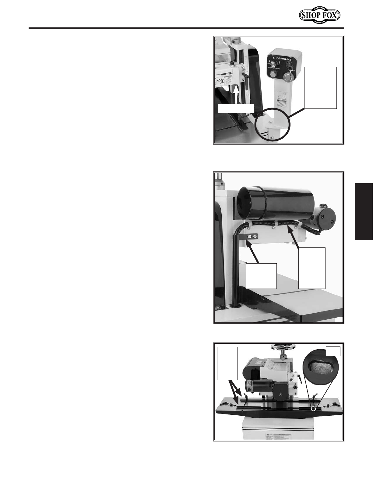
5. With the help of an assistant, lift the planer/moulder
head/table assembly and position it onto the stand,
as shown in Figure 11.
W1812 Owner's Manual (Mfd. Since 02/11)
Shipping
Brace
Brace
Mounting
Bolts
Figure 10. Shipping brace.
6. Remove the rear panel, then secure the head/table
5
to the stand with four
5
⁄16" flat washers.
⁄16"-18 x 3⁄4" hex bolts and
7. Place the belt onto the cutterhead pulley with the
belt direction arrow pointing the direction of pulley
SETUP
rotation. When installed correctly, the internal belt
tangs should be facing against the pulley rotation.
8. Keeping your fingers clear of pinch points, lift the
motor and roll the belt onto the motor pulley as
shown in Figure 12.
Figure 11. Placing planer/moulder on stand.
Internal
Belt Tang
Pulley Rotation
Direction
9. Attach the belt guard to the stand (see Figure
5
13) with two
washers, and two
⁄16"-18 x 3⁄4" hex bolts, four 5⁄16" flat
5
⁄16"-18 hex nuts.
10. Slide the handwheel hub over the shaft (see Figure
13) and tighten the set screw with a 5mm hex wrench.
-14-
Figure 12. Motor pulley belt installation.
Belt
Guard
Figure 13. Belt guard and handwheel instal-
lead.
Page 18
W1812 Owner's Manual (Mfd. Since 02/11)
11. Feed the control panel wiring harnesses through the
hole in the stand, and secure the pedestal control
panel to the stand, as shown in Figure 14, using
5
three
⁄16"-18 x 1" hex bolts and 5⁄16" flat washers.
12. Plug the harnesses into their respective sockets just
below the pedestal control panel.
5
Note: A
⁄16"-18 x 3⁄8" Phillips head screw is pre-
installed in the headstock to keep the moulding
knives clear of the table surface when the headstock
is at its lowest position. To replace the screw with
5
the included
⁄16"-18 x 1" depth stop bolt and hex
nut, simply remove the screw, thread the bolt with
the nut into the hole, then tighten the nut against
the headstock at the location shown in Figure 14.
1
The minimum workpiece thickness is
1
Phillips head screw and
⁄2" with the depth stop bolt.
⁄4" with the
Depth Stop
Figure 14. Control panel support
installation.
Control
Panel
Support
Mounting
Location
13. Insert the feed motor wiring harness through the
conduit and loom clamps, then plug it into the motor.
14. Fasten the conduit mounting bracket (see Figure
5
15) to the headstock with two
⁄16"-18 x 3⁄8" flange
screws.
15. Install two T-nuts in each table slot (see Figure 16).
16. Position the inner and outer guide rails so the
elongated T-nut slots (see Figure 16) are positioned
on the infeed table.
Conduit
Mounting
Bracket
Figure 15. Conduit installation.
Inner
and
Outer
Rails
SETUP
Wiring
Harness
and
Loom
Clamps
Slot
17. Insert the lock levers through the guide rails, then
thread them into the T-nuts.
18. Snug the levers in place.
-15-
Figure 16. Rail installation.
Page 19
W1812 Owner's Manual (Mfd. Since 02/11)
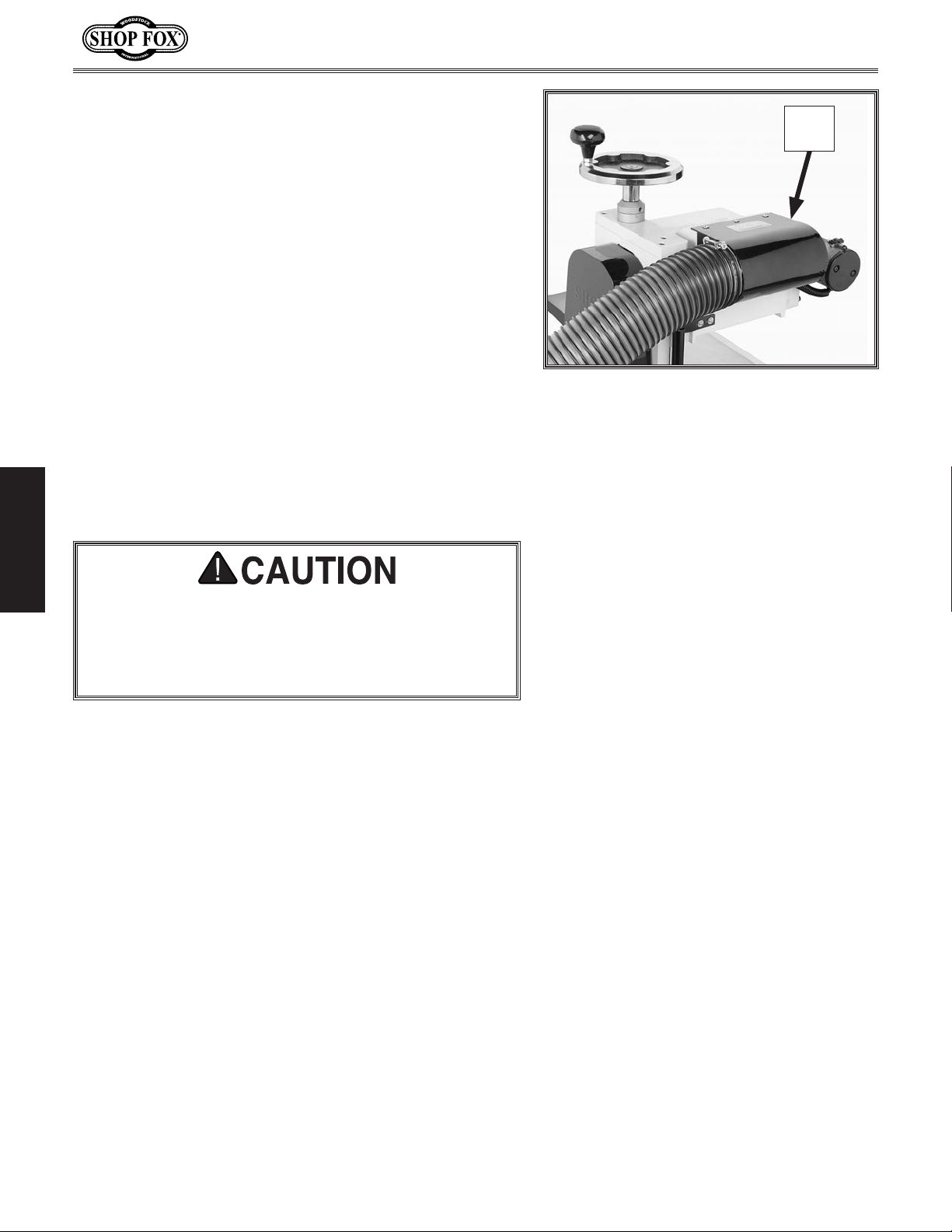
19. Install the dust hood (see Figure 17) with three #10-
20. Install a 4" flexible hose to the dust port, as shown in
1
⁄2" flange screws.
24 x
Figure 17.
Dust Collection
Recommended CFM at Dust Port: ................ 400 CFM
Do not confuse this CFM recommendation with the rating
of the dust collector. To determine the CFM at the
dust port, you must take into account many variables,
including the CFM rating of the dust collector, the length
of hose between the dust collector and the machine, the
number of branches or Y's, and the amount of other open
lines throughout the system. Explaining this calculation
is beyond the scope of this manual. If you are unsure of
your system, consult an expert or purchase a good dust
collection "how-to" book.
Dust
Hood
Figure 17. Installing the dust hood.
SETUP
DO NOT operate this machine without an adequate
dust collection system. This machine creates substantial amounts of wood dust while operating. Failure to
use a dust collection system can result in short and
long-term respiratory illness.
-16-
Page 20
W1812 Owner's Manual (Mfd. Since 02/11)
Test Run
Once the assembly is complete, test run your machine
to make sure it runs properly and is ready for regular
operation. The test run consists of verifying the
following: 1) The motor powers up and runs correctly,
and 2) the safety disabling mechanisms work correctly.
If, during the test run, you cannot easily locate the
source of an unusual noise or vibration, stop using the
machine immediately, then review Troubleshooting
on Page 42 for correction. If you still cannot remedy a
problem, contact our Tech Support at (360) 734-3482 for
assistance.
To test run the machine, do these steps:
1. DISCONNECT MACHINE FROM POWER AND MAKE SURE
KEY IS REMOVED FROM POWER SWITCH!
Projectiles thrown from the machine
could cause serious eye injury. Wear
safety glasses to reduce the risk of
injury.
2. Raise the headstock to provide plenty of room for
safe operation of the feed rollers and the cutterhead.
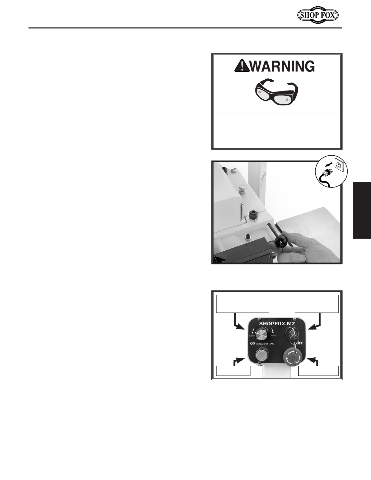
3. Pull out the retaining pin (see Figure 18) and remove
the chip deflector.
4. Refer to Installing Planer Knives in on Page 19, and
make sure the knives are tight and installed correctly.
5. Make sure the rest of the machine is set up properly.
6. Connect machine to power.
7. Push the OFF button in (see Figure 19), then turn it
clockwise so it pops out. This will ensure it resets.
8. Insert the power switch key (see Figure 19), and turn
it clockwise.
9. Push the ON button and the main motor will start.
10. Turn the speed control dial left and right to test the
feed motor speed control.
Figure 18. Removing chip deflector
retaining pin.
Conveyor Speed
Dial
Keyed Power
Switch
OFF ButtonON Button
SETUP
11. Reset the OFF button.
12. Press the OFF button to stop the machine.
13. WITHOUT resetting the OFF button, press the ON
button again. The machine should NOT start.
14. Remove the power switch key, and push the ON
button one last time. The machine should not start.
-17-
Figure 19. Control panel.
Page 21
OPERATIONS
General
This machine will perform many types of operations
that are beyond the scope of this manual. Many of these
operations can be dangerous or deadly if performed
incorrectly.
The instructions in this section are written with the
understanding that the operator has the necessary
knowledge and skills to operate this machine. If at any
time you are experiencing difficulties performing any
operation, stop using the machine!
If you are an inexperienced operator, we strongly
recommend that you read books or trade articles, or seek
training from an experienced planer/moulder operator
before performing any unfamiliar operations. Above all,
your safety should come first!
W1812 Owner's Manual (Mfd. Since 02/11)
READ and understand this entire instruction manual before using this machine.
Serious personal injury may occur if
safety and operational information is not
understood and followed. DO NOT risk
your safety by not reading!
Locking Power Switch
Children or untrained people can be killed or seriously
injured by this machine. This risk increases with
unsupervised operation. To help prevent unsupervised
OPERATIONS
operation, disable and lock the switch before leaving
machine unattended! Place the key in a well-hidden
or secure location.
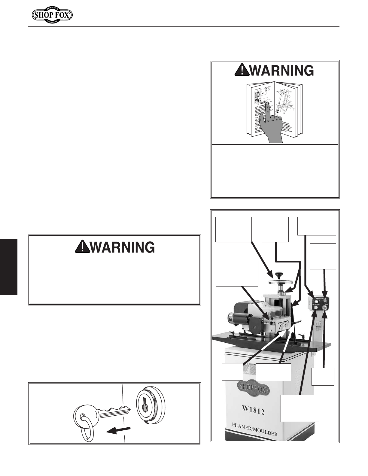
Removing the key from the power switch disables the
cutterhead ON button (see Figures 20 & 21) which
can prevent unauthorized machine operation. If the
machine is located where untrained people have access,
this is especially important. However, when adjusting
or servicing this machine, disabling the machine in this
manner is NOT a safe substitute for disconnecting the
machine completely from power.
Headstock
Height
Handwheel
Chip
Deflector
Retaining Pin
Depth
Stop
Cutting
Depth
Scales
Headstock
Lock Lever
Feed Speed
Dial
Locking
Power
Switch
Stop
Button
Figure 20. Disabling the machine.
Cutterhead
ON
Button
Figure 21. Machine controls.
-18-
Page 22
W1812 Owner's Manual (Mfd. Since 02/11)
Installing Planing Knives
WEAR thick gloves and use
extreme caution when working
near cutting surfaces. Planing
knives are dangerously sharp!
Failure to exercise care while
working near knives could result
in severe injury.
To install the planing knives, do these steps:
1. DISCONNECT MACHINE FROM POWER!
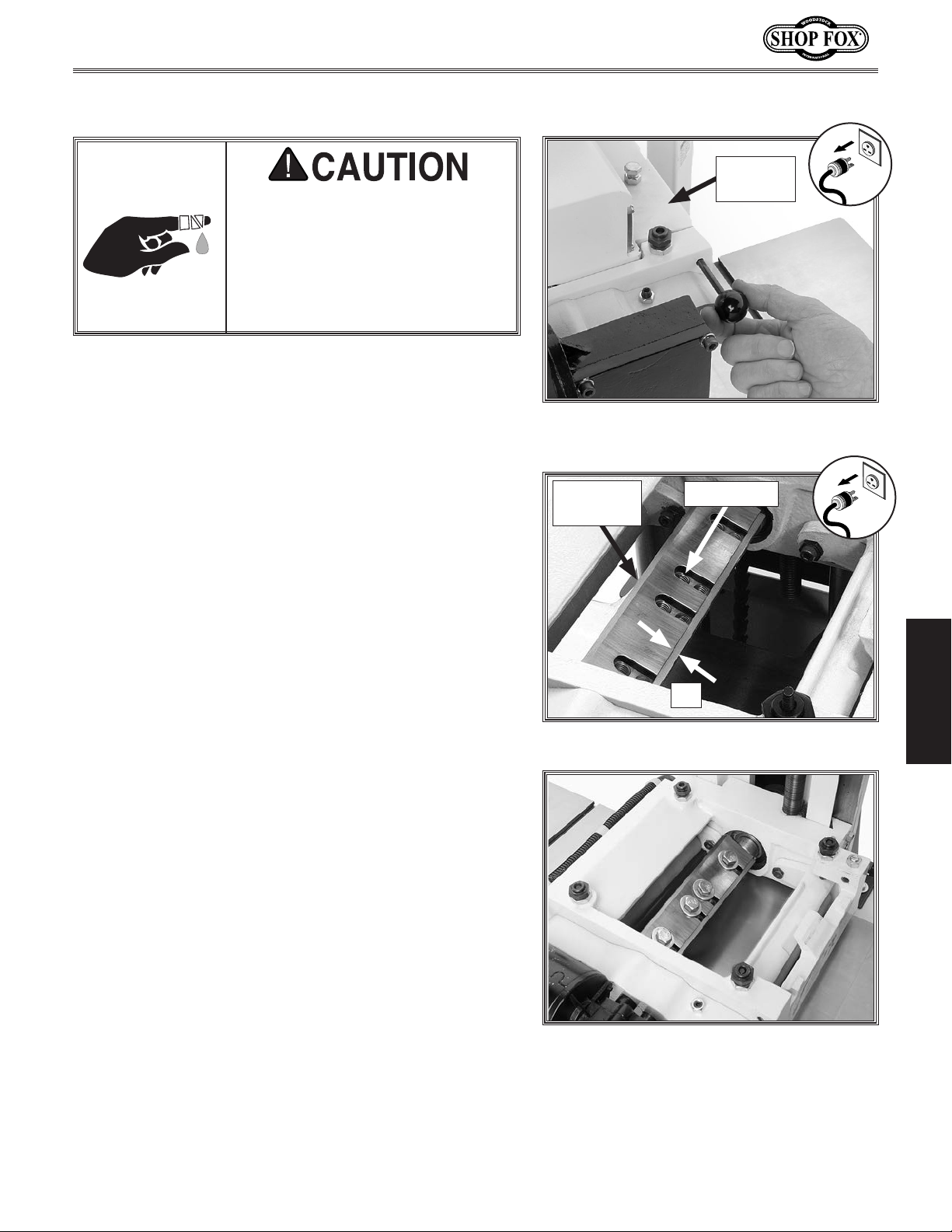
2. Pull the pin shown in Figure 22, and remove the chip
defle cto r.
Chip
Deflector
Figure 22. Removing chip deflector
retaining pin.
3. Put on heavy leather gloves, and use a 14mm wrench
to remove the knife bolts, washers, and any knives (if
installed).
4. Remove any dust, wood chips, or pitch from the
cutterhead where the planing knife will seat.
5. Place the new planing knife against the cutterhead lip
with the beveled side of the knife facing up, as shown
in Figure 23.
6. Line up the holes in the planing knife and the
cutterhead, and install a
flat washer in each of the upper hole positions shown
in Figure 23. Make sure to keep the planing knife
seated against the cutterhead lip while tightening the
bolts.
7. Visually inspect to make sure that the planing knife
did not move away from the cutterhead lip (see
Figure 24) during the tightening process. If so,
reinstall the knife until it is correctly seated.
3
⁄8"-16 x 1" knife bolt and 3⁄8"
Bevel Side
Up
Figure 23. Correct planing knife position.
Upper Hole
Lip
OPERATIONS
8. Rotate the cutterhead and install the other planing
knife.
9. Adjust the depth stop (see Figure 21) so the planing
knives stay clear of the table surface when the
headstock is at its lowest position.
10. Adjust the feed rollers and spring tension as outlined
in Feed Roller Height & Spring Tension on Page 21.
-19-
Figure 24. Planing knives installed.
Page 23
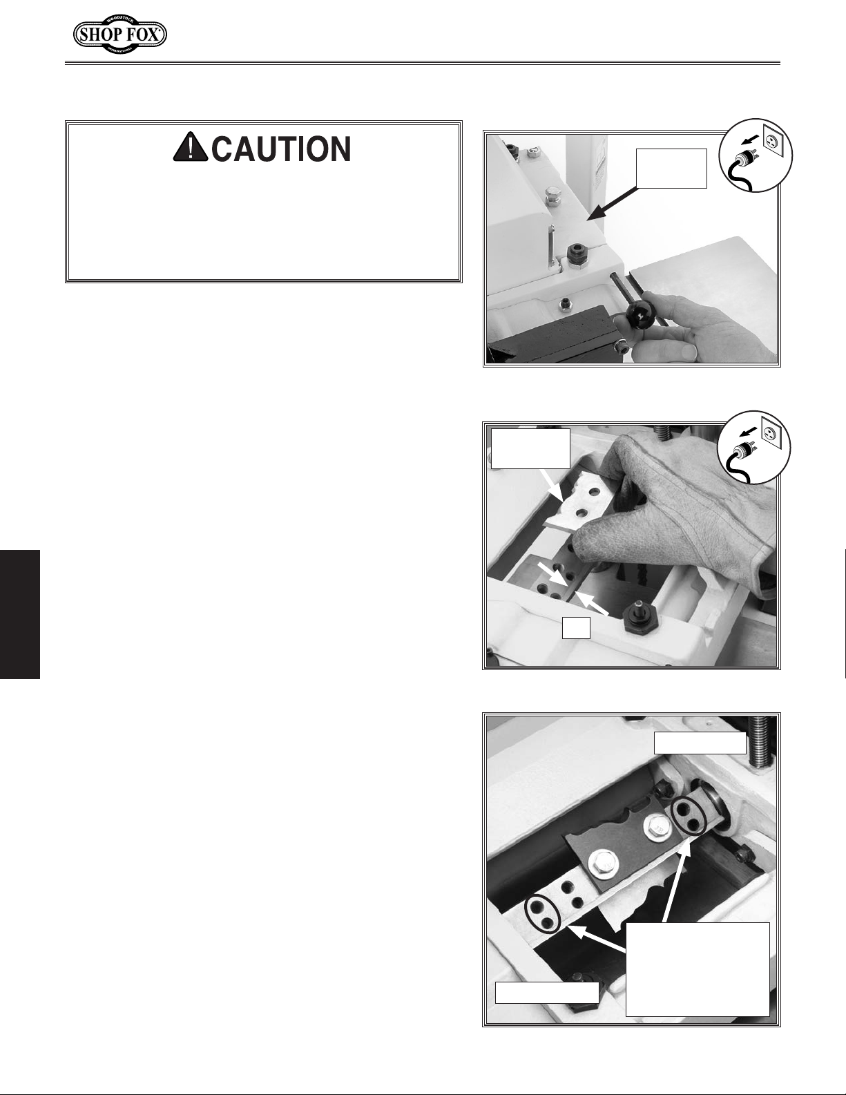
Installing Moulding Knives
Moulding knives have many different profiles. Before
starting the machine, always verify that the moulding knives do not contact any part of the workpiece
guide rails, feed roller swing arm, or the table surface. Failure to verify knife clearance may result in
severe injury and machine damage!
To install moulding knives, do these steps:
1. DISCONNECT MACHINE FROM POWER!
W1812 Owner's Manual (Mfd. Since 02/11)
Chip
Deflector
2. Pull the retaining pin shown in Figure 25, and remove
the chip deflector.
3. Put on heavy leather gloves, and use a 14mm wrench
to remove the knife bolts, washers, and knives (if
installed).
4. Remove any dust, wood chips, and pitch from the
cutterhead knife seat and lip (see Figure 26).
5. With the beveled side of the knife facing up, place
the moulding knife against the cutterhead lip as
shown in Figure 26.
6. Slide the knife to the inboard side of the cutterhead
and fasten it with the knife bolts as shown in Figure
OPERATIONS
27. Typically only one set of holes will be open on the
inboard side.
7. Make sure the knife did not move away from the
cutterhead lip when tightened, then rotate the
cutterhead and install the other moulding knife.
Figure 25. Removing chip deflector
retaining pin.
Bevel Side
Up
Lip
Figure 26. Installing moulding knife.
Inboard Side
8. Set the guide rail alignment so the edge of the
knives do not hit the rails, and adjust the depth stop
(see Figure 21) so the moulding knives stay clear of
the table surface when the headstock is at its lowest
position.
9. Adjust the feed rollers and spring tension as outlined
in Feed Roller Height & Spring Tension on Page 21.
-20-
For Clearance
Safety, Leave These
Holes Exposed
Outboard Side
Figure 27. Knives positioned inboard.
If Using Large
Moulding Knives
Page 24
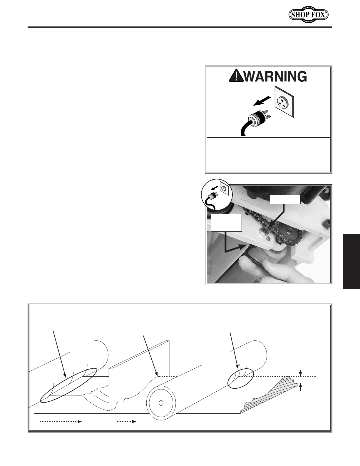
W1812 Owner's Manual (Mfd. Since 02/11)
Feed Roller Height &
Spring Tension
After switching between planing and molding operations,
you must re-adjust the feed roller height and spring
tension, so the workpiece is drawn through the planer/
moulder without chatter or slip. Rollers that are too high,
or have light spring tension can cause workpiece chatter
or slip. Feed rollers that are too low or have excessive
spring tension can make workpiece insertion into the
planer/moulder difficult, and prematurely wear the feed
roller shafts and bearings. The settings below are starting
points and some trial-and-error when adjusting will be
required.
To adjust the feed roller height and spring tension, do
these steps:
1. DISCONNECT MACHINE FROM POWER!
MAKE SURE that your machine is
unplugged during all adjustment
procedures! If this warning is ignored,
serious personal injury may occur.
2. Loosen the lock nuts (see Figure 28) and rotate the
eccentric stops with a 5mm hex wrench until the
rollers are positioned as follows:
—For planing, lower the roller approximately 1mm
below the lowest sweep of the planing knife.
3
—For moulding, lower the roller approximately
below the highest point of the moulding knife
profile. Refer to Figure 29 to find the highest point
of the moulding knife profile when the knife is at
the lowest point of its sweep.
Wide Surface
Area Traction
Infeed
Roller
Highest Point of this
Moulding Knife Profile
is Here
Knife at
Lowest
Point of
Sweep
⁄16''
Lock Nut
Eccentric
Stop
Figure 28. Adjusting feed roller height.
Narrow
Surface Area
Traction
Outfeed
Roller
Infeed and
Outfeed Rollers
are Adjusted to
Approximately
3
⁄16'' Below
the Highest
Resulting
Profile.
OPERATIONS
Work Path
Figure 29. Relationship between feed roller height and moulding knife profile.
-21-
Page 25
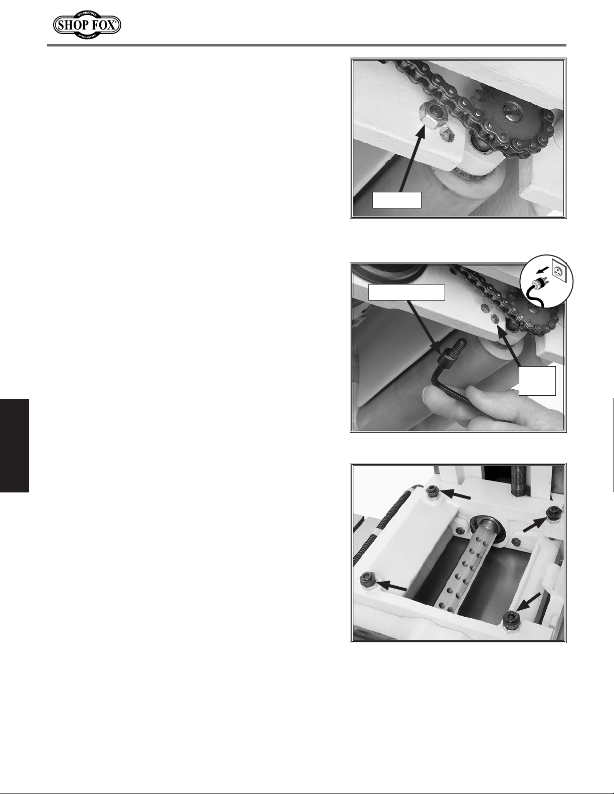
—If a certain moulding knife profile does not allow
you to adjust the outfeed roller down far enough
for proper roller traction, the eccentric stop must
be repositioned to the lower hole. To do this,
remove the lock nut (see Figure 30), reposition
the eccentric stop in the lower hole (see Figure
31), and finger tighten the lock nut. Next, rotate
the eccentric stop to lower or raise the roller, and
retighten the lock nut.
W1812 Owner's Manual (Mfd. Since 02/11)
Lock Nut
Figure 30. Lower hole for alternate stop
location.
Eccentric Stop
3. Completely loosen the four spring tensioner nuts (see
OPERATIONS
Figure 32), and unthread the tensioner assemblies
until they are not touching the springs.
4. Thread the tensioners back into the housings until
you feel the tensioner just contact the springs.
5. Rotate each tensioner approximately two full turns to
preload the springs, then tighten the nuts.
6. Reinstall the chip deflector.
Lower
Hole
Figure 31. Removing eccentric stop.
Figure 32. Feed roller spring tension nuts.
-22-
Page 26
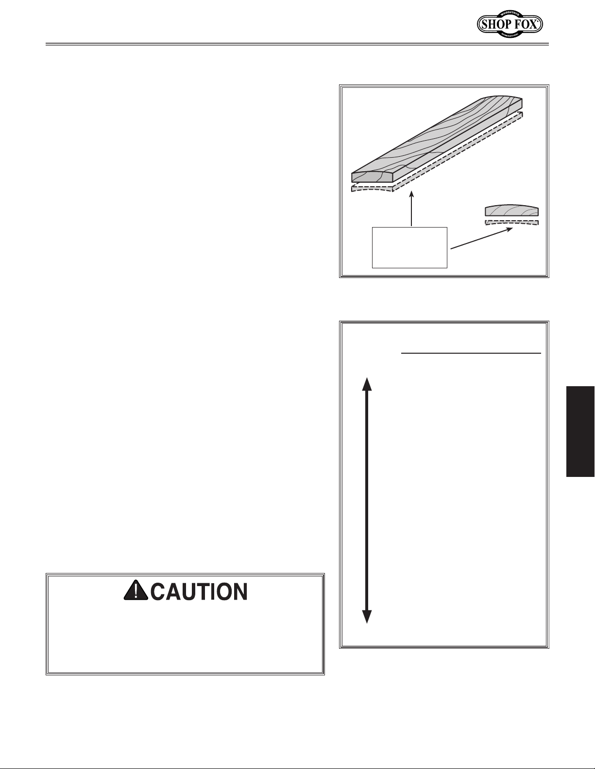
W1812 Owner's Manual (Mfd. Since 02/11)
Workpiece Inspection
Before using this planer/moulder, inspect each and every
workpiece for the following problems, and be familiar
with the hardness of the wood.
• Each workpiece must have at least one flat surface to
slide along the planer/moulder table. To create a flat
surface, pass the workpiece over a jointer (see Figure
33). Defects such as twisting, loose knots or severe
cracks may make the stock unusable.
• When possible, square up stock before moulding.
Plane equal amounts on each side of the board to
reduce the chance of twisting or cupping.
• Recognize the workpiece density. Planing is more
difficult in hard species of wood and may require
several shallow cuts to reach the desired thickness.
Figure 34 lists the hardness of many common woods
based on shear strength.
Portion
Removed with
Jointer
Figure 33. Face joint the concave side of
cupped
workpiece
before milling.
• Only use clean lumber. Scrape off all glue from joined
boards before processing. Remove all dirt, nails,
staples, imbedded gravel, etc. from any workpiece
you plan on using. Metal or gravel in a workpiece will
instantly damage the knives.
• Avoid processing a workpiece with a high moisture
content. Wood with more than 20% moisture, or wood
that has been exposed to rain or snow, will cut poorly
and cause unnecessary wear on the knives and motor.
• Process ONLY wooden workpieces. Never process
particle board, plywood, MDF, laminates, or other
synthetic materials.
• Feed wood in the same direction as the grain. Never
feed end-cut or end-grained lumber into the planer/
mo uld er.
ONLY cut wood with this machine! Cutting workpieces
that are made of or contain plastic, melamine,
metal, fiberglass, epoxy, resins, glues, or other non
wood materials can lead to machine damage or serious personal injury!
TYPE .............SHEAR (PSI)
HARD
SOFT
Figure 34. Wood density table.
Black Locust ............. 2,480
Sugar Maple ............. 2,330
Pecan Hickory ........... 2,080
White Oak ............... 2,000
White Ash ................ 1,950
Black Cherry ............ 1,70 0
American Elm ........... 1,510
Black Walnut ............ 1,410
Red Alder ................ 1,370
Basswood ................ 1,280
Cottonwood ............. 1,16 0
Western Larch ...........1,150
Tamarack .................1,130
Douglas Fir .............. 1,0 80
Alaska Cedar ............ 1,050
Sitka Spruce ............. 1,000
Sugar Pine ................. 980
Cypress ..................... 940
Redwood (OG) ............ 930
Red Cedar ................. 860
White Pine ................. 850
Balsam Fir ................. 710
OPERATIONS
-23-
Page 27
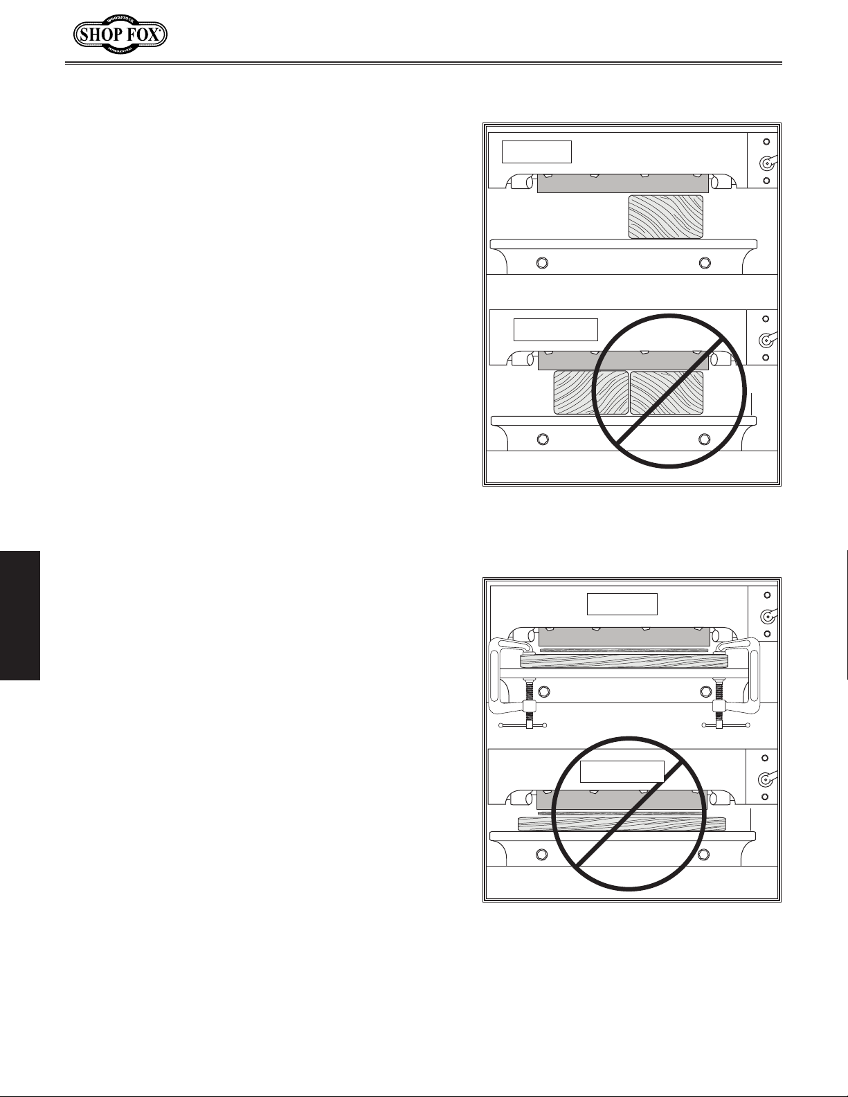
Planing Do's & Don'ts
There are common mistakes that must be avoided when
planing.
Multiple Boards
Only plane one board at a time (see Figure 35). Whether
you use guide rails or not, never attempt to plane more
than one board at a time side-by-side. If one board is
slightly lower that the other, the feed roller will only
hold the highest board, while the lower board will be
free to slip when the knife contacts it. This hazardous
situation can result in one board being ejected from the
machine, causing serious injury.
W1812 Owner's Manual (Mfd. Since 02/11)
CORRECT
INCORRECT
Sacrificial Table Use
If using a sacrificial table, you must clamp it to the cast
iron table (see Figure 36) to prevent workpiece ejection.
Never stack two boards on top of one another and feed
them both into the planer/moulder to compensate for a
workpiece that may be too thin. Planing with two loose
OPERATIONS
stacked boards can result in workpiece ejection, causing
injury.
Figure 35. Only plane one board at a
time.
CORRECT
INCORRECT
-24-
Figure 36. Sacrificial table mounting.
Page 28
W1812 Owner's Manual (Mfd. Since 02/11)
Planing Operation
The maximum cutting depth for soft wood at full
cutterhead width is no more than
keep in mind that the harder the wood, the shallower the
cutting depth and the slower the feed rate should be. A
series of light passes typically results in a smoother finish
with less snipe.
The basic steps for operating the machine as a planer
are as follows:
1. DISCONNECT MACHINE FROM POWER!
2. Review the Workpiece Inspection list on Page 23
and the AVOIDING KICKBACK warning on this page.
3. Review Planing Do's & Don'ts on Page 24, and take
the appropriate safety measures.
4. If you have not already done so, adjust the feed
rollers and spring tension as outlined in the Feed
Roller Height & Spring Tension section on Page 21.
5. Measure the workpiece thickness, loosen the
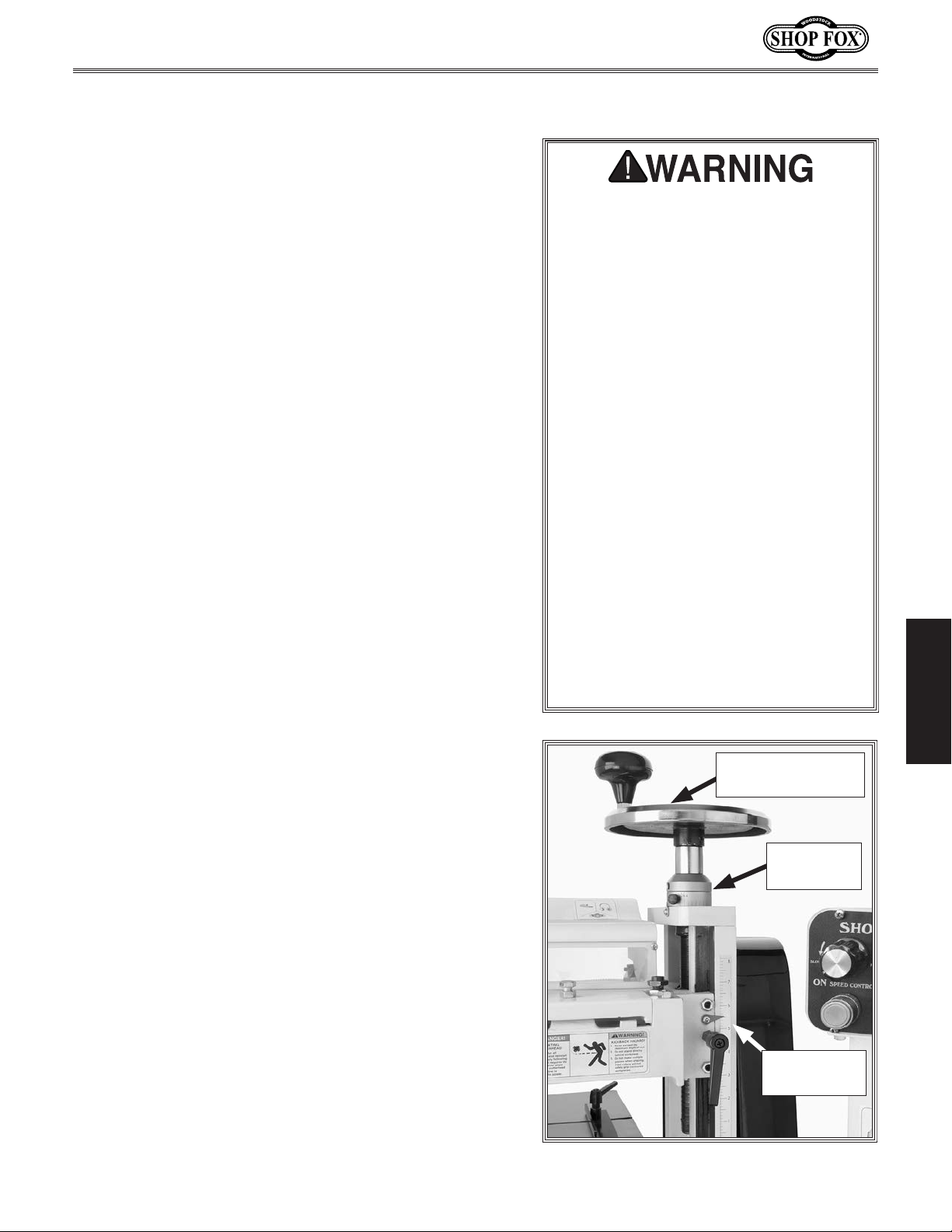
headstock lock lever, and use the handwheel (see
Figure 37) to adjust the headstock for a light pass.
6. Wearing gloves, manually rotate the cutterhead to
make sure that the knives do not contact the table
or guide rails if used.
1
⁄8" deep; however,
AVOIDING KICKBACK!
• Always stand to one side of the
machine—rather than behind the
workpiece.
• DO NOT plane more than one piece
at a time.
• Always plane WITH the grain
direction of the wood. Never plain
cross-grain or end-grain.
1
• DO NOT remove more than
material on each pass.
• Support the workpiece on both
ends. Get assistance if you are
planing long lumber, or use roller
stands to support the workpiece.
• Carefully inspect all stock to make
sure it is free of large knots or
foreign objects that may damage
your knives.
⁄8'' of
OPERATIONS
7. PUT ON SAFETY GLASSES, EAR PROTECTION, AND A
RESPIRATOR.
8. Tighten the headstock lock lever, start the machine,
and turn the feed speed control dial to a medium
speed.
9. Stand clear of the workpiece path, place the flat
side of the board down on the table, and slowly feed
the workpiece into the machine until the feed roller
begins to pull the workpiece.
10. For subsequent passes, adjust the headstock
height and feed rate as necessary until the desired
thickness and finish is achieved.
Note: To reduce snipe, use roller tables and feed
multiple pieces of stock butted up end-to-end, or
experiment with a lighter feed roller spring tension.
You can also try to raise one or both feed rollers up
slightly.
-25-
Headstock
Height Handwheel
Handwheel
Scale
Headstock
Height Scale
Figure 37. Depth controls and scales.
Page 29
Moulding Do's & Don'ts
The Model W1812 will accommodate most moulding knife
profiles. However, you must still pay special attention to
workpiece support and knife-to-table clearance. Refer to
the following examples to avoid common workpiece setup
mistakes.
Moulding knives have many different profiles. Before
starting the machine, always verify that the moulding knives do not contact any part of the workpiece
guide rails, feed roller swing arm, or the table surface. Failure to verify knife clearance may result in
severe injury and machine damage!
W1812 Owner's Manual (Mfd. Since 02/11)
CORRECT
End View
CORRECT
Edge-Forming Knife Clearance
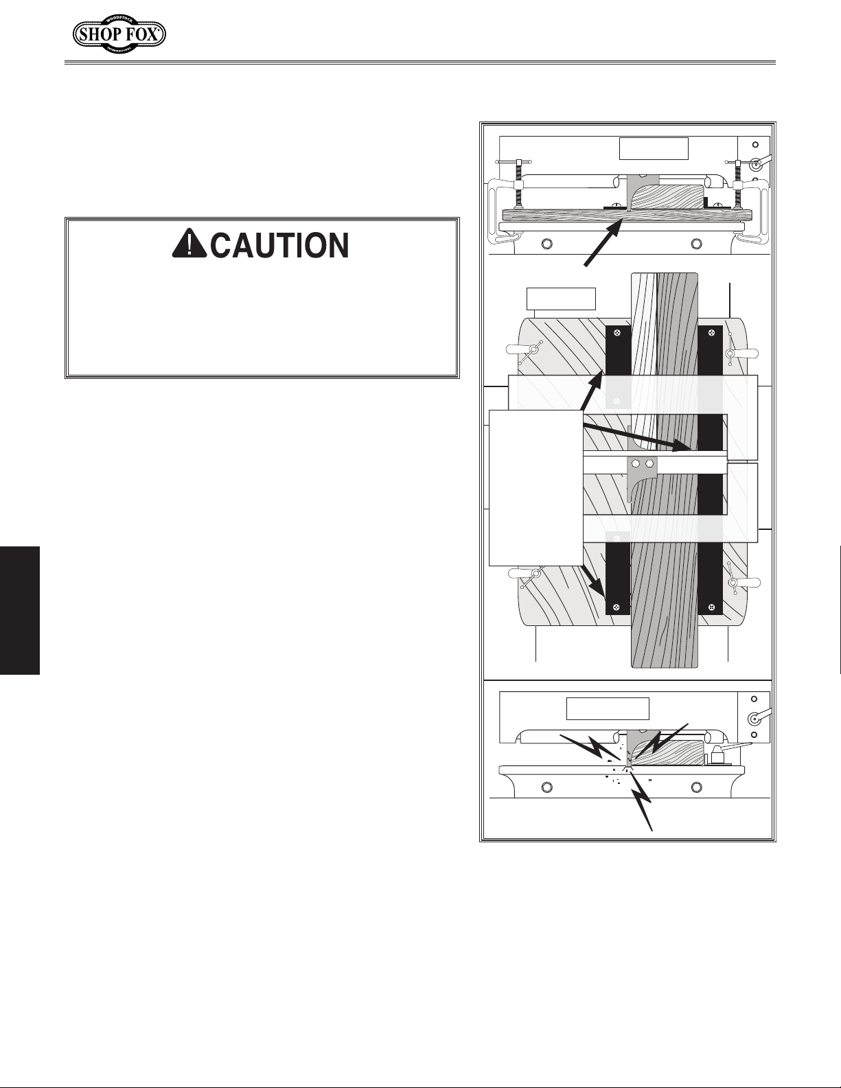
A wooden sacrificial table clamped to the cast iron
table and a three-piece guide system (see Figure 38)
can prevent tool and table damage by absorbing the full
sweep of the knife.
Never attempt to use edge-forming profile knives without
pre-installing a wooden sacrificial table. Often these types
of knives sweep lower than the workpiece and could
contact the table at the bottom, as shown in Figure 38,
causing severe machine damage or personal injury.
OPERATIONS
Custom
3-Piece
Guide
Rail System
Mounted to
the
Sacrificial
Table
Top View
INCORRECT
-26-
End View
Figure 38. Edge-forming profile hazards.
Page 30
W1812 Owner's Manual (Mfd. Since 02/11)
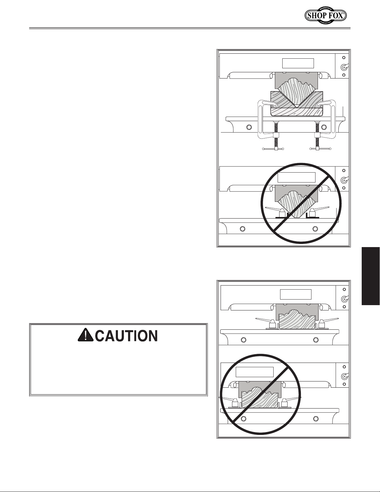
Crown Moulding Support
When cutting crown moulding (see Figure 39), make a
wooden V-track that can be clamped to the table. The
V-track must support at least 50% of the workpiece height
on both sides.
Do not use the guide rails that came with your machine
for crown moulding support. If you do, the workpiece can
dislodge and be ejected from the machine, causing severe
injury or damage.
CORRECT
INCORRECT
Knife Positioning
When cutting harder woods, some moulding knife profiles
are prone to vibration that leave chatter marks on the
workpiece. To counteract this problem you can stabilize
the cut by installing the moulding knives closer to column
for the best support (see Figure 40).
Moulding knives have many different profiles. Before
starting the machine, always verify that the moulding knives do not contact any part of the workpiece
guide rails, feed roller swing arm, or the table surface. Failure to verify knife clearance may result in
severe injury and machine damage!
Figure 39. Crown moulding track.
CORRECT
INCORRECT
OPERATIONS
-27-
Figure 40. Knife positioning.
Page 31
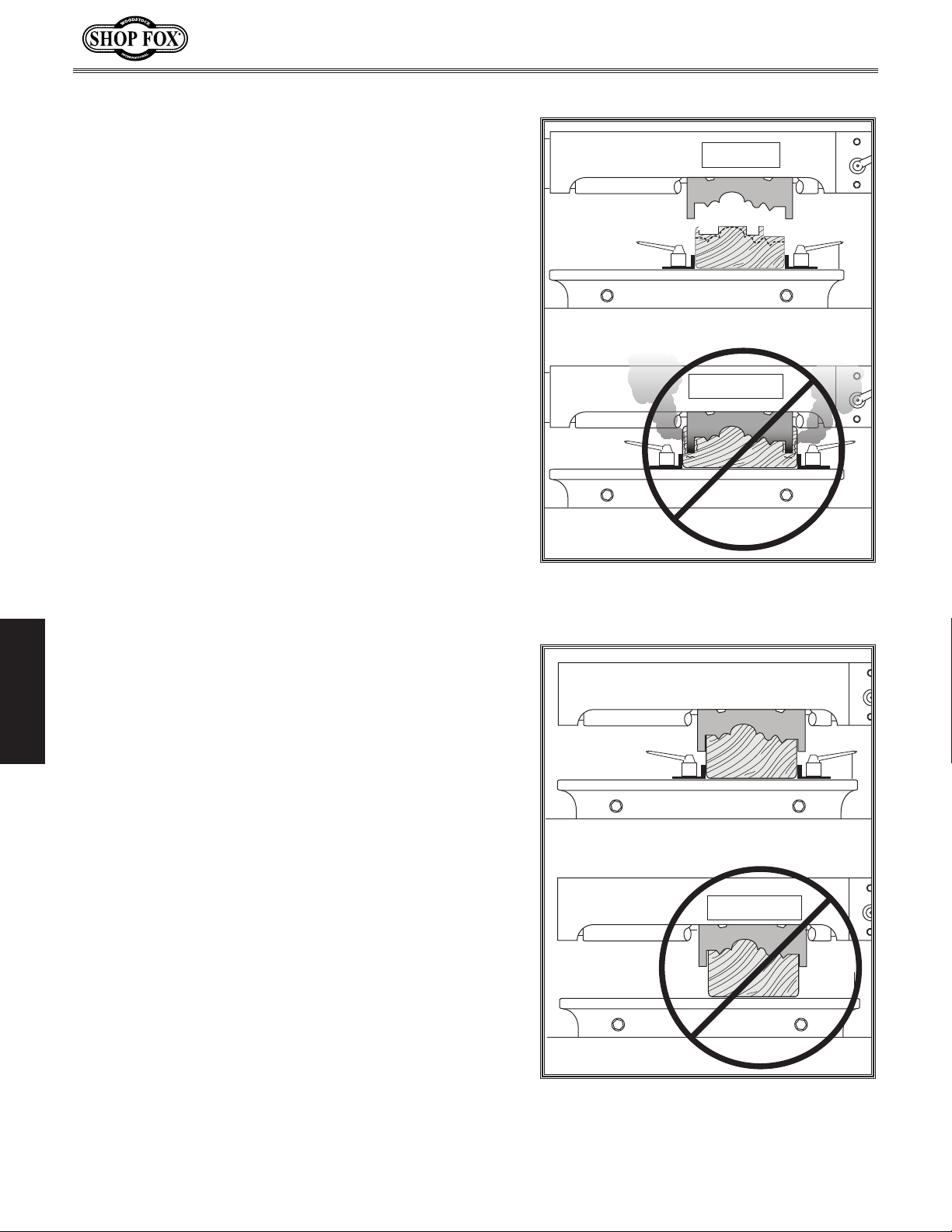
Size Workpiece Appropriately
Make sure to cut your workpiece to the correct width for
the knife being used (see Figure 41). To improve knife life
and workpiece results when cutting in very hard woods,
use a table saw to rabbet out some of the profile before
running the workpiece through the planer/moulder.
Never cut into moulding that is wider than the knife.
Otherwise, the knife will overheat, burn the wood, and
dull rapidly.
W1812 Owner's Manual (Mfd. Since 02/11)
CORRECT
INCORRECT
Always Use Guide Rails When Moulding
Make sure to use the guide rails (see Figure 42), so the
moulding profile can be cut with maximum safety and
without wander, twisting, or profile misalignment.
Do not attempt to cut moulding without using the guide
OPERATIONS
rails. Otherwise, the workpiece could shift and be ejected
from the machine, or the moulding pattern could be
inconsistent from one strip of molding to another.
Figure 41. Correct workpiece sizing.
CORRECT
INCORRECT
-28-
Figure 42. Using the guide rails.
Page 32
W1812 Owner's Manual (Mfd. Since 02/11)
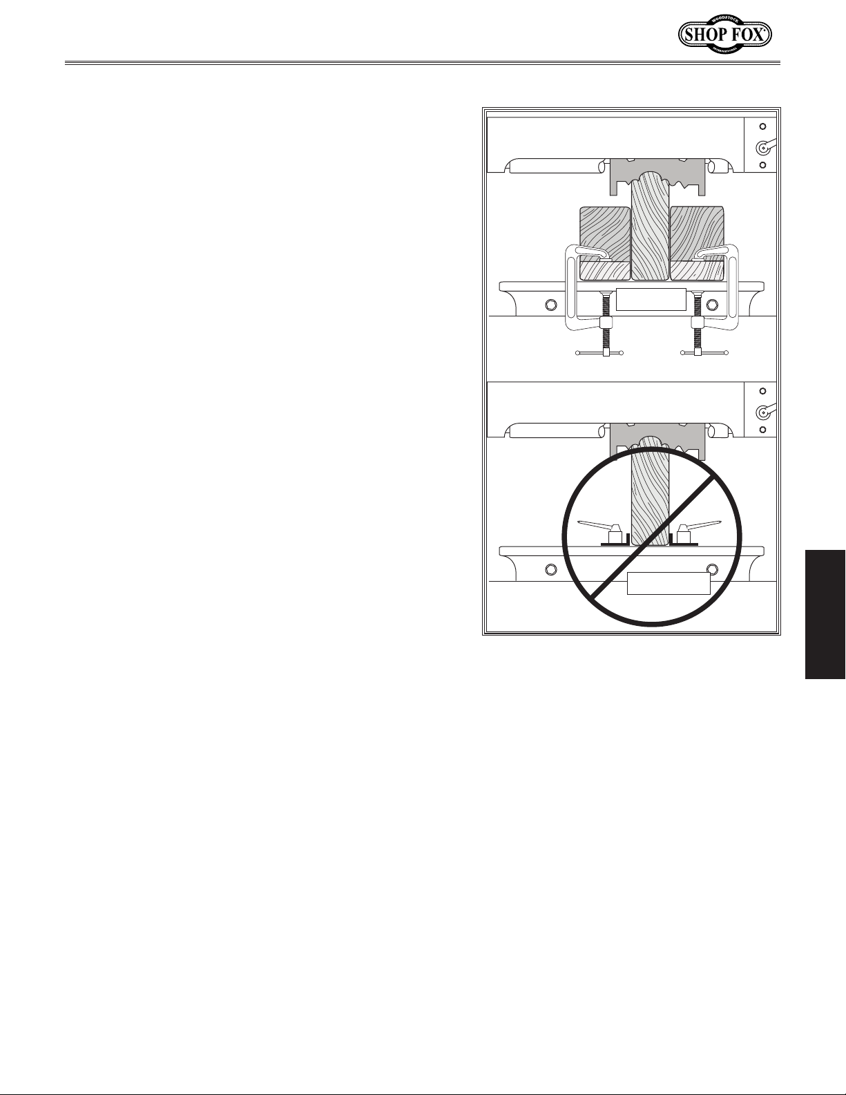
Edge Moulding Tall Workpieces
When cutting edge profiles on workpieces that are taller
than they are wide, you must clamp wooden extension
rails to the table so they support at least 75% of the
workpiece height on both sides (see Figure 43).
Never attempt to use the low profile metal guide rails
that came with this machine if they do not adequately
support tall workpieces. If the workpiece slips out of the
rails because they are too low, the workpiece can be
ejected from the machine, causing severe injury.
CORRECT
INCORRECT
Figure 43. Correct support for tall
workpieces.
OPERATIONS
-29-
Page 33
Moulding Operation
The maximum depth of a moulding cut in soft wood is
3
⁄4". For hard or knotty wood the maximum depth of cut
must be less, and the feed rate may have to be reduced.
If both of these options are not enough, then a table saw
can be used to rabbet out some of the material that the
knives would of have had to remove. See Figure 41 for an
example of this.
The basic steps for a moulding operation are as follows:
1. DISCONNECT MACHINE FROM POWER!
W1812 Owner's Manual (Mfd. Since 02/11)
AVOIDING KICKBACK!
• Always stand to one side of the
machine—rather than directly
behind the workpiece.
• Always check and reset outfeed
roller height after changing knives.
2. Review the Workpiece Inspection list on Page 23
and the AVOIDING KICKBACK warning on this page.
3. Review Moulding Do's & Don'ts on Page 26, and take
the appropriate safety measures.
4. Adjust the guide rails against the sides of the
workpiece it will be is directed into the planing
knives without binding, then tighten the rail lock
levers.
5. If you have not already done so, adjust the feed
rollers and spring tension as outlined in the Feed
Roller Height & Spring Tension section on Page 21.
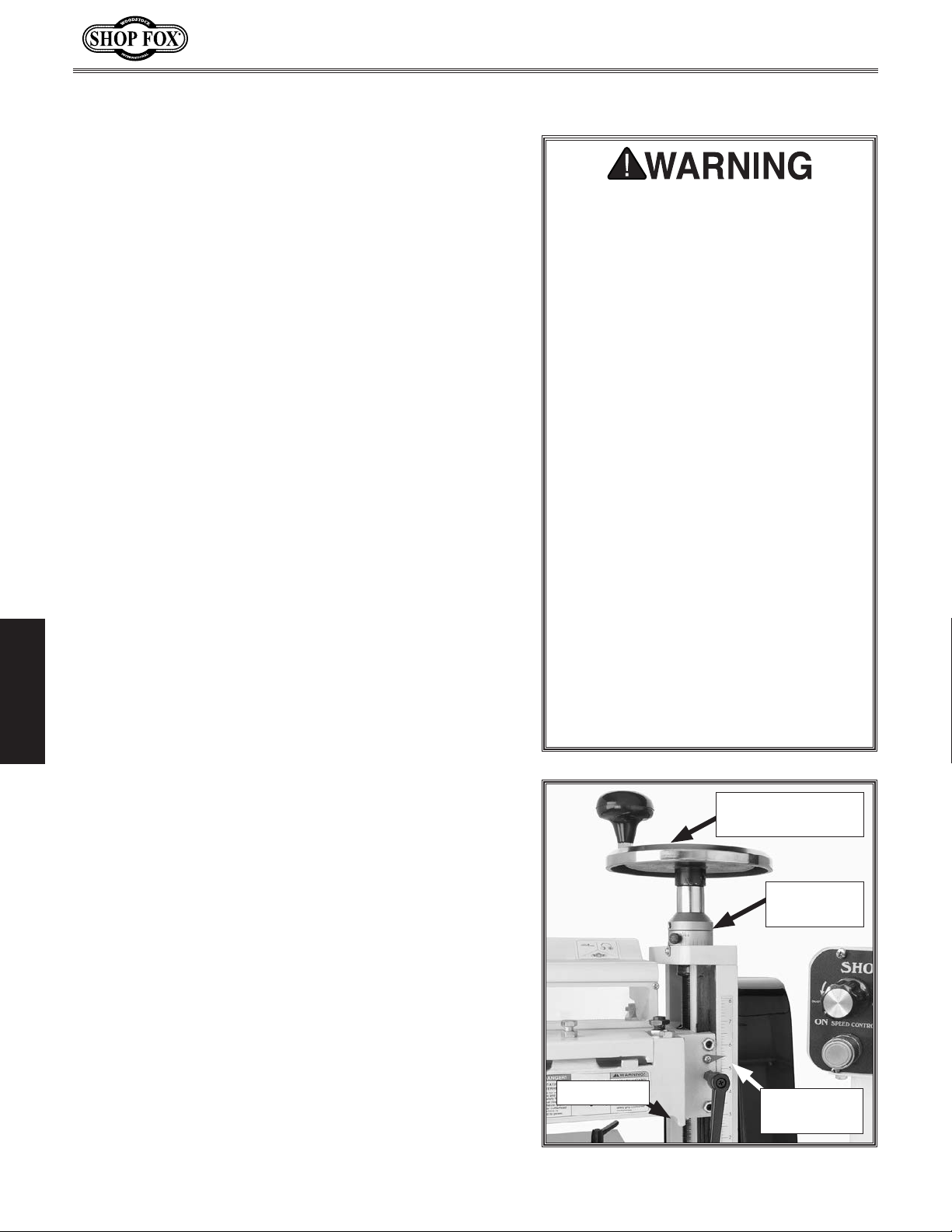
6. Loosen the headstock lock lever, and use the
handwheel (see Figure 44) to adjust the headstock
down far enough to make a full pass.
OPERATIONS
7. Put on heavy leather gloves and rotate the
cutterhead manually to verify that the knives do not
contact the table or the guide rails.
8. PUT ON SAFETY GLASSES, EAR PROTECTION, AND A
RESPIRATOR.
9. Connect the machine to power.
• Always cut mouldings WITH the
grain direction. Never cut across
the grain or on the end-grain.
• Do not make a second pass after
cutting the initial profile. The first
pass has full roller-to-workpiece
contact, but on the second pass,
both the infeed and outfeed rollers
have minimum contact and the
workpiece may be ejected.
• Use roller stands to support long
workpieces.
• Carefully inspect all stock to make
sure it is free of large knots and
foreign objects.
Headstock
Height Handwheel
Handwheel
Scale
10. Turn the feed speed control dial to a slow speed
and start the machine. Finding the best feed rate
will be a process of trial-and-error based on finding
a balance between the wood type, moulding knife
profile, and the quality of finish desired.
11. Stand to the side of the table, place the workpiece
on the table, and slowly feed it into the machine
until the feed roller begins to pull the workpiece.
-30-
Depth Stop
Figure 44. Depth controls and scales.
Headstock
Height Scale
Page 34
W1812 Owner's Manual (Mfd. Since 02/11)
ACCESSORIES
The following planer/moulder accessories may be available through your local Woodstock International
Inc. dealer. If you do not have a dealer in your area, these products are also available through online
dealers. Please call or e-mail Woodstock International Inc. Customer Service to get a current listing of
dealers at: 1-800-840-8420 or at [email protected].
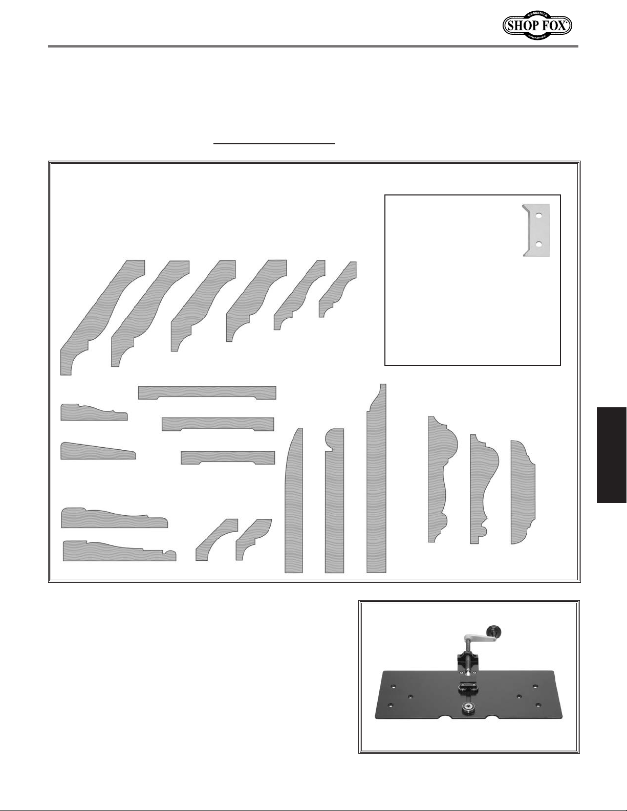
Moulding Knives
This selection of HSS Moulding Knives fits our Shop Fox®
Planer/Moulders. Each moulding profile includes a set of
two indexable knives, so knife setting is quick and easy.
D3338
45⁄8" Crown
D3337
41⁄4" Crown
D3336
35⁄8" Crown
D3335
31⁄4" Crown
D3334
23⁄4" Crown
D3333
21⁄4" Crown
BACK CUTTERS
For Crown Moulding Knives
(Sold in pairs).
D3674 Back Cutter for D3333 21⁄4" Crown
D3675 Back Cutter for D3334 23⁄4" Crown
D3676 Back Cutter for D3335 31⁄4" Crown
D3677 Back Cutter for D3336 35⁄8" Crown
D3678 Back Cutter for D3337 41⁄4" Crown
D3679 Back Cutter for D3338 45⁄8" Crown
D3332 2" Back Out
D3326
2" Casing
D3327
21⁄4" Casing
D3328
31⁄4" Casing
D3329
31⁄2" Casing
D3331 1
D3330 1
D3324
13⁄4" Cove
1
⁄2" Back Out
1
⁄8" Back Out
D3325
13⁄4" Bed
D3343
31⁄4"
Base
D3342
31⁄4"
Base
Model D3393—Elliptical Jig
This is an ideal accessory to create round-top windows
and arched panelways that are characteristic of custom woodwork. Using the existing guide rail mounting
hardware from the W1812 planer/moulder, this jig easily
fastens to the planer/moulder table. The jig hand crank
feeds arched wood into the cutterhead to create extremely high quality casings and mouldings that match any previously cut straight mouldings with the same profile. This
3
jig requires a shop-made
⁄4" thick template of the same
arc or radius as the workpiece. Maximum width capacity
1
⁄2".
is 5
D3344
41⁄4"
Base
D3341
3" Chair Rail
D3339
25⁄8" Chair
Rail
Figure 45. Model D3393 elliptical jig.
D3340
21⁄2" Chair
Rail
OPERATIONS
-31-
Page 35
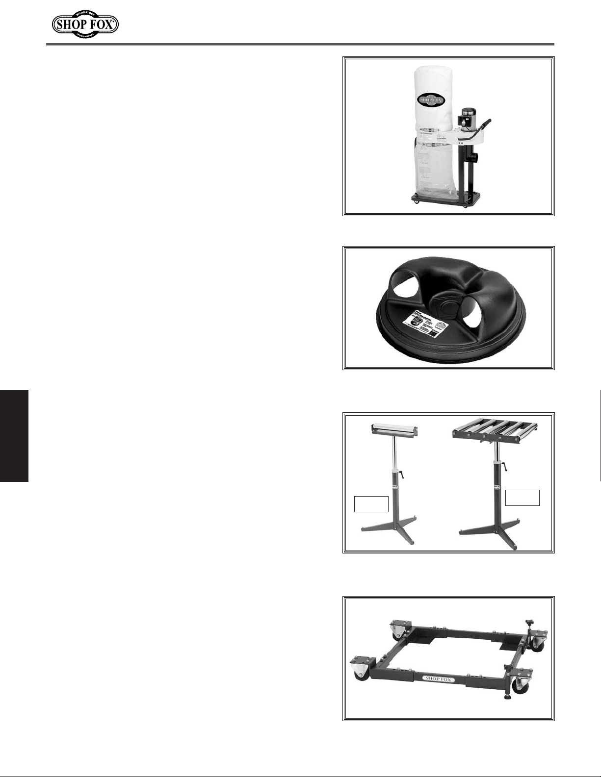
W1727—1 HP Dust Collector
A perfect dedicated dust collector for a planer/moulder
on a job site or in a shop. The motor is 1H P, 11 0 V/22 0V,
single-phase; and the flow specifications are 800 CFM with
a static pressure of 5.67 " H
O. The bag capacity is 2.1
2
cubic feet with a filtration level down to 2.5-micron.
W1049—Large Dust Collection Separator
Our Dust Collection Separator increases the chip collection capacity of dust collection systems that are rated 800
CFM or greater. Designed to fit securely on top of a standard 30-gallon metal trash can, this molded ABS fitting
is engineered to use cyclonic action to drop out larger
particles from the dust flow. The fitting features molded
inlets and outlets that can be easily connected to standard systems using 4" flexible hose. You'll be amazed at
how well it works!
W1812 Owner's Manual (Mfd. Since 02/11)
Figure 46. W1727 1HP dust collector.
Figure 47. W1049 large dust collection
separator.
Model D2273—Single Roller Stand
Large diameter ball bearing roller stand features smooth
operation for a variety of processing and work support
applications. Heavy pedestal base is stable and secure.
OPERATIONS
Mod e l D2274 —5 Roller Stand
For greater work stability and support, this 5 roller stand
features large diameter, ball bearing rollers mounted on a
sturdy adjustable pedestal base.
D2057A—Heavy-Duty Shop Fox Mobile Base
Make your machine mobile with this popular patented mobile base. The unique outrigger type supports
increased stability and lower machine height. This heavy
duty mobile base is rated for up to a 600 lb. capacity.
D2273
D2274
Figure 48. Models D2273 and D2274 Shop
Fox roller stands.
-32-
Figure 49. D2057A Shop Fox mobile base.
Page 36
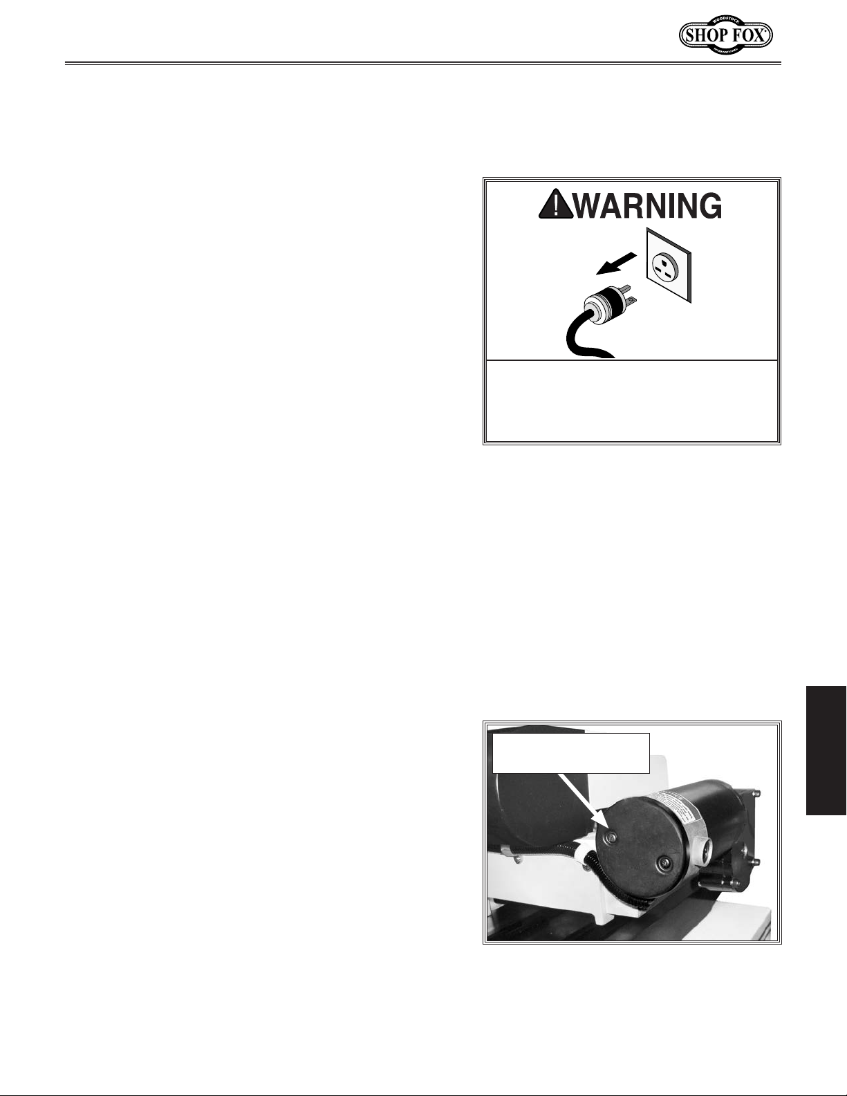
W1812 Owner's Manual (Mfd. Since 02/11)
MAINTENANCE
General
Regular maintenance on your machine will ensure its
optimum performance. Make a habit of inspecting your
machine each time you use it.
• Loose mounting bolts.
• Worn switch, damaged cords, and plugs.
• Damaged V-belt.
• Any other unsafe condition.
Cleaning
Frequently vacuum sawdust away from the internal
working parts of the machine and motor fan cover. Dust
build-up around the motor is a sure way to decrease its
lifespan.
Occasionally it will become necessary to clean the
internal parts with mineral spirits and a stiff brush.
Make sure the internal workings are dry and have been
re-lubricated before using the machine again. When using
mineral spirits and cleaners, do not allow them to contact
the viewing window or it may become etched and cloudy.
Remove the chip deflector, and use only warm water with
a mild dish soap to clean the window. Do not let water
come in contact with metal parts or rust may occur.
Cleaning Feed Motor
Every three months of daily use, remove the motor dust
cover (see Figure 50), and vacuum the carbon dust
buildup from inside of the motor. Under very heavy-use,
increase the cleaning interval. DO NOT blow motor out
with compressed air, as this may force contaminants into
bearings!
MAKE SURE that your machine is
unplugged during all maintenance
procedures! If this warning is ignored,
serious personal injury may occur.
MAINTENANCE
Motor Dust Cover and
Retaining Screws
Table & Base
Tables can be kept rust-free with regular applications
of products like SLIPIT
want to consider products like Boeshield T-9™.
®
. For long term storage you may
-33-
Figure 50. Feed motor dust cover.
Page 37
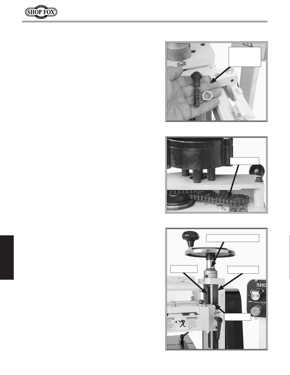
Lubrication
Figures 51—53 show lubrication locations that need
attention every six months; however, under heavy use or
adverse working conditions, increase lubrication intervals
accordingly.
Since all bearings are sealed and permanently lubricated,
simply leave them alone until they need to be replaced.
To lubricate the machine, do these steps:
1. DISCONNECT MACHINE FROM POWER!
2. Measure and record the distance each tensioner
protrudes from the top of the headstock.
3. Loosen the nuts and un-thread the tensioner
assemblies, one of which is shown in Figure 51.
W1812 Owner's Manual (Mfd. Since 02/11)
One of Four
Tensioner
Assemblies
Figure 51. Tensioner assembly.
4. Clean the tensioner assembly with mineral spirits,
apply a thin layer of light machine oil or motor oil,
and reinstall the tensioner to the previously recorded
height.
5. Place the nozzle under the chain housing, vacuum
out all dust, then brush a coat of light machine oil or
motor oil on the drive chains (see Figure 52).
6. Clean the column ways and leadscrew with mineral
spirits, and brush a coat of light machine oil or motor
oil on all cleaned locations (see Figure 53).
7. Apply a few drops of light machine oil or motor oil
onto the gib at the top, so the oil drains down inside
the gib seat, keeping the gib lubricated.
8. Apply a few drops of light machine oil or motor oil
onto the handwheel scale hub, and work the hub to
make sure that it draws the oil down inside.
MAINTENANCE
9. Wipe away excess oil with a clean rag.
Drive Chain
Figure 52. Drive chain assembly.
Handwheel Scale Hub
Leadscrew
Column Way
-34-
Top of Gib
Figure 53. Gib, way, and leadscrew
locations.
Page 38
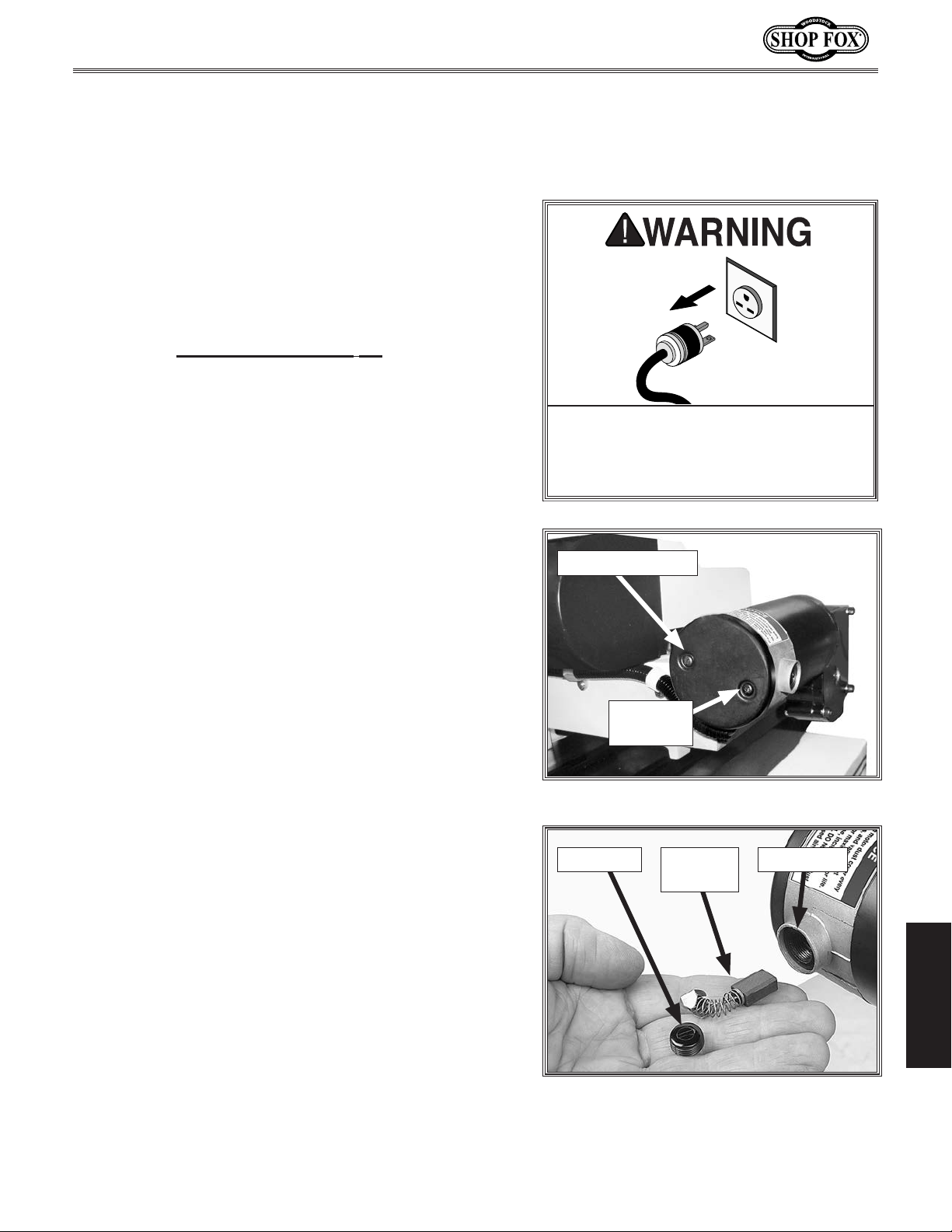
W1812 Owner's Manual (Mfd. Since 02/11)
SERVICE
General
This section covers the most common service adjustments
or procedures that may need to be made during the life
of your machine.
If you require additional machine service information
not included in this section, please contact Woodstock
International Technical Support at (360) 734-3482 or send
an e-mail to: tech-support@shopfox.biz.
Changing Feed Motor
Brushes
If the feed motor fails, is noisy, warmer than usual, or
appears to run sluggishly, the brushes may need to be
replaced.
To replace feed motor brushes, do these steps:
1. DISCONNECT MACHINE FROM POWER!
2. Unscrew both dust cover retaining screws and
remove the dust cover shown in Figure 54.
3. Unscrew the brush caps from both sides of the
motor, and remove the brushes, as shown in Figure
55.
4. Vacuum carbon dust from the motor and both brush
bores. DO NOT blow dust out with compressed air!
5. Insert new brushes into the slots located on both
side of the brush bores.
MAKE SURE that your machine is
unplugged during all service procedures! If this warning is ignored, serious personal injury may occur.
Motor Dust Cover
Retaining
Screw
Figure 54. Feed motor end view.
Brush Cap
Assembly
Brush BoreBrush
6. Reinstall the brush caps.
7. Reinstall the motor dust cover.
8. Test run the feed motor.
SERVICE
Figure 55. Feed motor brush and cap.
-35-
Page 39
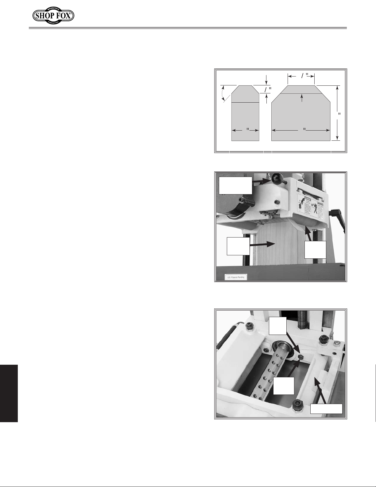
Feed Roller-to-Table
Alignment
W1812 Owner's Manual (Mfd. Since 02/11)
The feed rollers must be aligned correctly with the table
to maintain a smooth and straight feed.
To check the feed roller-to-table alignment, do these
steps:
1. DISCONNECT MACHINE FROM POWER!
2. Pull the retaining pin out (see Figure 57), and set the
chip deflector aside.
3. Make the wooden gauge block shown in Figure 56.
4. Place the finished block on the table, directly under
one end of the infeed roller, as shown in Figure 57.
5. Lower the cutterhead housing so the infeed roller
barely touches the gauge block the lowest end of the
roller (see Figure 57).
6. Slide the block over to the other end of the roller.
7. Using a set of feeler gauges, measure the gap
between the roller and the block.
1
1
2
1
45°
2
Side View
Figure 56. Gauge block dimensions.
Retaining
Pin
Gauge
Block
2
Grain
Direction
4
Front View
Feed
Roller
4
—If the gap is more than 0.005", proceed to Step 8
and adjust the swing arm downward so the roller
just touches the block or the gap is less than 0.005".
8. Loosen the cap screw shown in Figure 58, then
rotate the cam nut until the swingarm lowers or
raises, so the roller just touches the block without
compressing the roller springs.
9. Remove the gauge block and retighten the cap screw.
10. Check and adjust the outfeed roller in the same
manner as above.
11. Complete the Feed Roller Height & Spring Tension
adjustments on Page 21.
SERVICE
12. When finished, reinstall the chip deflector.
Figure 57. Gauge block placed under feed
rol le r.
Cam
Nut
Cap
Screw
Swingarm
Figure 58. Feed roller components.
-36-
Page 40
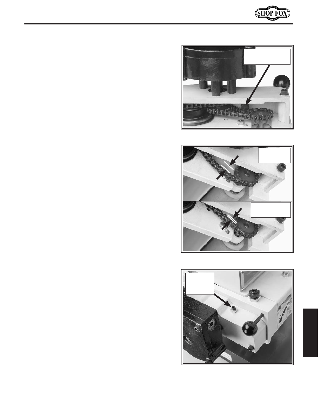
W1812 Owner's Manual (Mfd. Since 02/11)
Drive Chain Adjustment
After long-term machine use, the rubber pad on the end
of the drive chain tensioner (see Figure 59) will wear.
The result is that the drive chain will become overly slack
and can jump its sprockets, causing damage. This situation
can be avoided by removing the excess chain slack.
When properly adjusted, keep in mind that the chain
should not be in tension like a V-belt, but rather it should
hang slightly with 3-5mm of hanging slack (see Figure
60), so the sprocket shafts are free floating with no chain
tension against them.
Chain Tensioner
Rubber Pad
To remove excess chain slack, do these steps:
1. DISCONNECT MACHINE FROM POWER!
2. Raise the headstock until you have easy access to the
chain area.
3. Loosen the lock nut on the chain tensioner screw (see
Figure 61).
4. Use a 4mm hex wrench to adjust the tensioner until
there is 3-5mm of hanging slack in the chain (see
Figure 60).
5. Tighten the lock nut, and test the operation.
Figure 59. Drive chain tensioner rubber pad.
Excessive
Chain Slack
Correct Chain
Slack 3-5mm
Figure 60. Chain slack examples.
Chain
Tensioner
Screw
-37-
SERVICE
Figure 61. Chain tensioner screw location.
Page 41
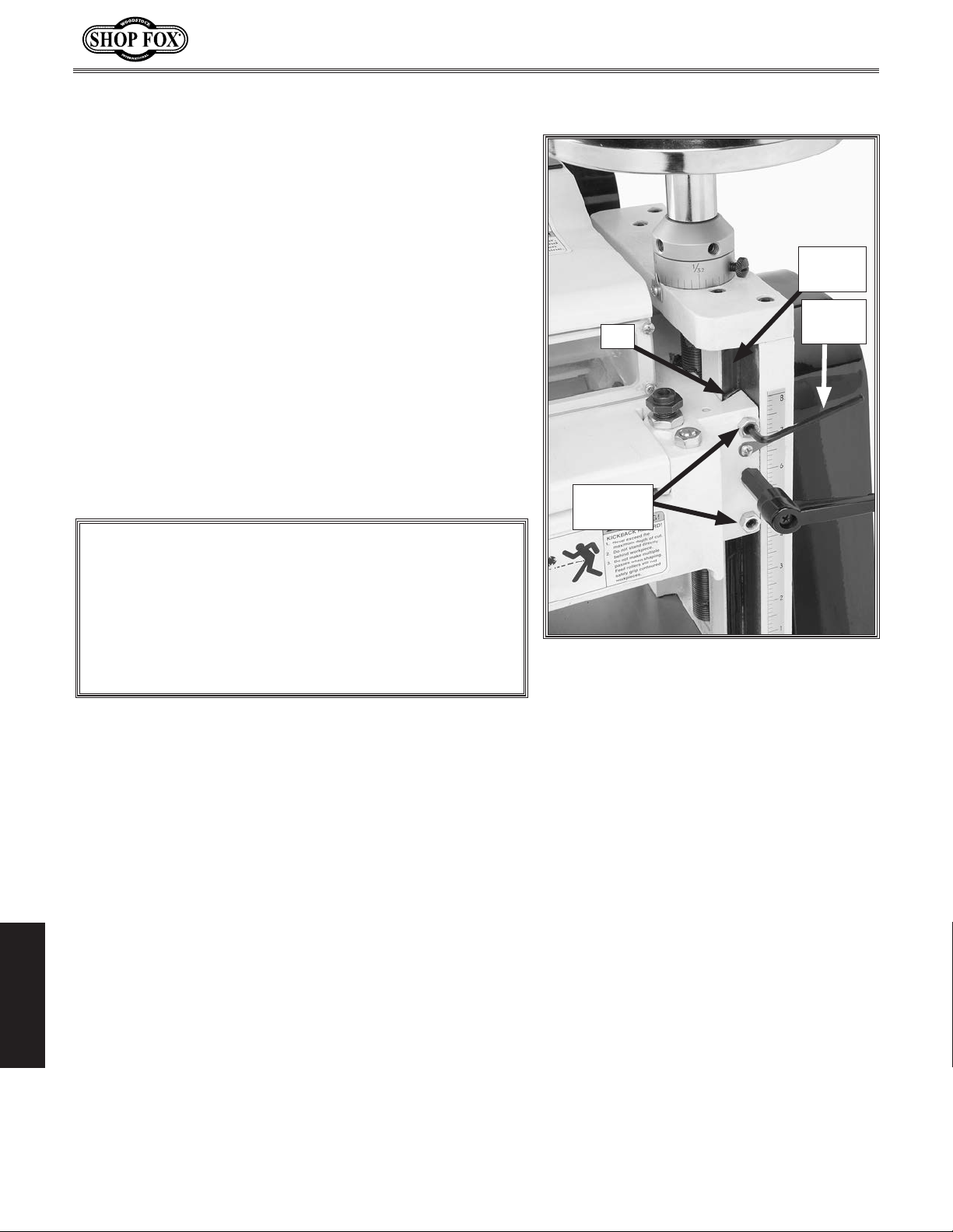
Gib Adjustment
Due to normal wear, the headstock gib will eventually
have to be re-adjusted to remove any play in the ways.
To adjust the headstock gib, do these steps:
1. DISCONNECT MACHINE FROM POWER!
2. Clean and lubricate the column leadscrew, gib, and
ways.
3. Loosen the gib lock nuts shown in Figure 62.
4. Using a 4mm hex wrench, adjust the upper and lower
gib screws in an alternating fashion until a slight
drag is detected in the headstock slide when the
handwheel is cranked.
W1812 Owner's Manual (Mfd. Since 02/11)
Column
Way
Hex
Gib
Wrench
5. Tighten the lock nuts.
NOTICE
When adjusting gibs, the goal is to remove unnecessary sloppiness or binding from the headstock when
it slides up and down on the column. A loose gib
will allow the headstock to vibrate and the knives
to chatter. An overly tight gib will prematurely wear
the column and leadscrew.
Gib Lock
Nuts
Figure 62. Gib locations.
SERVICE
-38-
Page 42
W1812 Owner's Manual (Mfd. Since 02/11)
SHOCK HAZARD.
QUALIFIED ELECTRICIAN
WIRE CONNECTIONS.
WIRE/COMPONENT DAMAGE
. The motor wiring shown in these
shocked, wait at least this long before working
Electrical Safety Instructions
These pages are current at the time of printing. However, in the spirit of improvement, we
may make changes to the electrical systems of future machines. Study this diagram carefully.
If you notice differences between your machine and these wiring diagrams, call Woodstock
International Technical Support at (360) 734-3482.
connected to a power source is extremely
dangerous. Touching electrified parts will
result in personal injury including but not
limited to severe burns, electrocution,
or death. Disconnect the power from
the machine before servicing electrical
components!
hazards of electricity, only a qualified
electrician should perform wiring tasks on this
machine. If you are not a qualified electrician,
get help from one before attempting any kind
of wiring job.
tight to prevent wires from loosening during
machine operation. Double-check all wires
disconnected or connected during any wiring
task to ensure tight connections.
or components increase the risk of serious
personal injury, fire, or machine damage.
If you notice that any wires or components
are damaged while performing a wiring task,
replace those wires or components before
completing the task.
Working on wiring that is
. Due to the inherent
All connections must be
. Damaged wires
MOTOR WIRING
diagrams is current at the time of printing,
but it may not match your machine. Always
use the wiring diagram inside the motor
junction box.
MODIFICATIONS. Using aftermarket parts or
modifying the wiring beyond what is shown
in the diagram may lead to unpredictable
results, including serious injury or fire.
CAPACITORS/INVERTERS. Some capacitors and
power inverters store an electrical charge for
up to five minutes after being disconnected
from the power source. To avoid being
on these components.
ELECTRICAL REQUIREMENTS. You MUST follow
the electrical requirements at the beginning
of this manual when connecting your machine
to a power source.
EXPERIENCING DIFFICULTIES. If you are
experiencing difficulties understanding the
information included in this section, contact
our Technical Support at (360) 734-3482.
The photos and diagrams
included in this section are
best viewed in color. You
can view these pages in
color at www.shopfox.biz.
BLACK
WHITE
GREEN
RED
WIRING DIAGRAM COLOR KEY
BLUE
BROWN
GRAY
ORANGE
-39-
YELLOW
YELLOW
GREEN
PURPLE
PINK
LIGHT
BLUE
BLUE
WHITE
TURQUOISE
SERVICE
Page 43
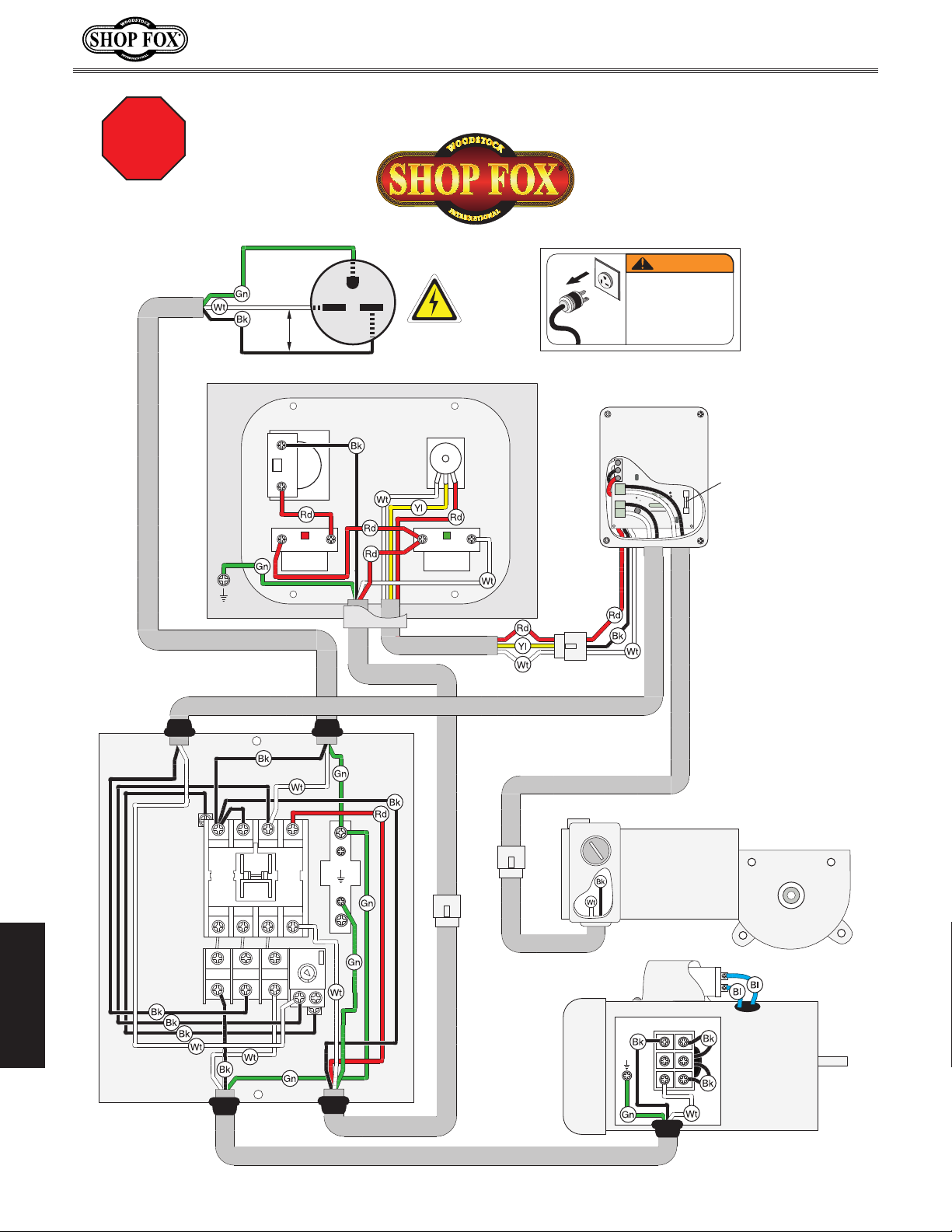
W1812 Owner's Manual (Mfd. Since 02/11)
Ground
Read
Page 39
STOP
Before
Wiring
Machine Power Cord
Ground
230
VAC
Control Box
Hot
Hot
Keyed Power
Switch
Emergency
Stop
Wiring Diagram
6-15 Plug
G
230 VAC
Control Panel
(Rear View)
Speed Dial
On Button
Wiring Diagram
WARNING
ACCIDENTAL INJURY
HAZARD!
Disconnect power
supply before
adjustments, setup,
or maintenance!
Console Unit
Circuit
Board
MOTOR
SPEED
+
–
MOTOR
L2
L1
AC IN
3 Amp
Fuse
Plug
Control Cord
Console Unit Power Cord
Magnetic
Switch
MA-09
Contactor
RA-20
Thermal
Overload
L1/1 L3/5 7L2/3
T1/2 T3/6 8
T2/4
1/2
3/4
5/6
Assembly
Plug
RA-20
AMP
RESET
18A
12A
15A
96
98
Feed Motor Power Cord
Plug
Universal DC
Brush-Style
Feed Motor
180VDC
Capacitor
Control Panel Power Cord
SERVICE
Cutterhead
Induction
Motor
240 VAC
Cutterhead Motor Power Cord
-40-
Page 44
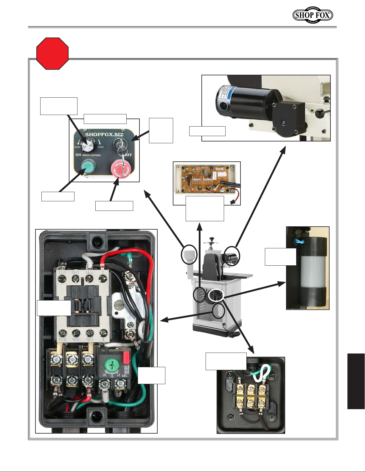
W1812 Owner's Manual (Mfd. Since 02/11)
Read
Page 39
STOP
Before
Wiring
Feed Speed
Dial
ON Switch
Electrical Component Locations
Control Panel
OFF Switch
Keyed
Power
Switch
Feed Motor
Feed Motor
Circuit
Board
Magnetic
Contactor
Thermal
Relay
Motor
Junction Box
Start
Capacitor
SERVICE
Figure 63. Electrical component locations.
-41-
Page 45
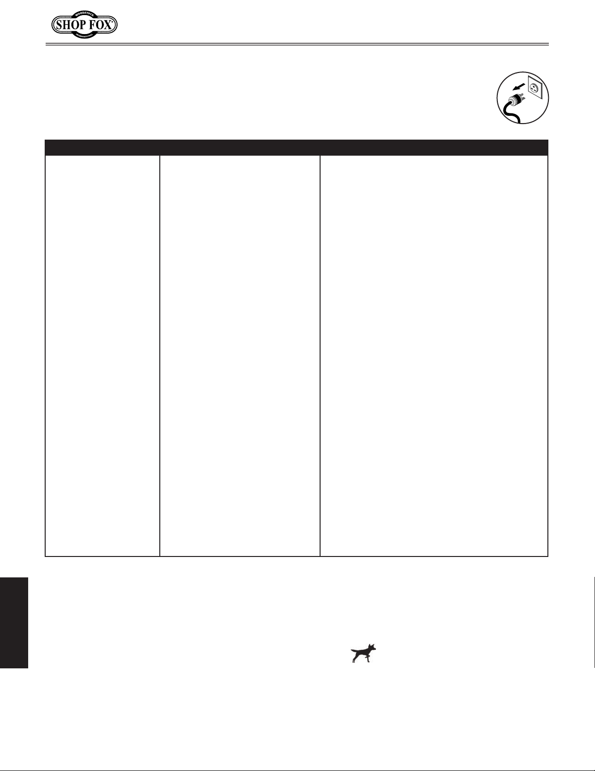
W1812 Owner's Manual (Mfd. Since 02/11)
Continued on next page
Troubleshooting
This section covers the most common problems and corrections with this type of
machine. WARNING! DO NOT make any adjustments until power is disconnected and
moving parts have come to a complete stop!
PROBLEM POSSIBLE CAUSE CORRECTIVE ACTION
Motor will not start. 1. The OFF Button is applied, or the
power switch is at fault.
2. Break or short in wiring; or loose
connections.
3. Has incorrect power supply voltage/power supply switch is OFF.
4. Blown fuse tripped circuit breaker
at main panel.
5. Thermal overload relay in mag
switch tripped (main motor only).
6. Motor connection wired incorrectly.
7. Contactor not energized/has poor
contacts (main motor only).
8. Motor ON switch at fault (main
motor only).
9. Plug or receptacle is corroded or
mis-wired.
10. Start capacitor has blown (main
motor only).
11. Circuit board fuse has blown (feed
motor only).
12. Motor speed rheostat at fault
(feed motor only).
13. Motor brushes worn/at fault (feed
motor only).
14. Centrifugal switch at fault (main
motor only).
15. Motor at fault. 15. Test for shorted windings or bad bearings; repair or
1. Turn the power switch on with its key, reset or
replace the OFF Button or power switch.
2. Trace/replace broken or corroded wires; fix loose
connections (wiring diagram on Page 40).
3. Verify and correct voltage/insert the key and turn
the power switch ON.
4. Repair for short, then reset/replace fuse or breaker.
5. Allow relay/motor to cool. If necessary, press reset
button inside switch.
6. Wire motor correctly (refer to inside junction box
cover or manual wiring diagram on Page 40).
7. Test all legs for power, test field coil and replace if
at fault (wiring diagram on Page 40).
8. Replace switch.
9. Clean/retighten contacts; correct the wiring (wiring
diagram on Page 40).
10. Test/replace if at fault.
11. Correct overload cause; replace blown fuse on circuit board.
12. Test/replace if at fault.
13. Replace brush set.
14. Adjust/replace centrifugal switch.
replace.
SERVICE
-42-
Page 46

W1812 Owner's Manual (Mfd. Since 02/11)
PROBLEM POSSIBLE CAUSE CORRECTIVE ACTION
Machine has excessive
vibration or noise.
Machine stalls or slows
when operating.
Handwheel binds or is
difficult to move.
1. Motor fan rubbing on fan cover. 1. Fix/replace fan cover; replace loose or damaged
2. Machine incorrectly mounted on
floor or mobile base.
3. Motor mounting loose. 3. Tighten mounting bolts/nuts; use thread locking
4. V-belt at fault. 4. Replace V-belt.
5. Headstock gib loose. 5. Clean, re-lubricate, and readjust headstock gib
6. Knives are dull. 6. Re-sharpen/replace knives.
7. Motor brushes worn/at fault (feed
motor only).
8. Pulley loose or not in alignment;
shaft bent.
9. Gearbox at fault (feed motor
only).
10. Centrifugal switch out of
adjustment; at fault (main motor
only).
11. Motor bearings worn or damaged. 11. Replace motor bearings or replace motor.
12. Cutterhead bearings at fault. 12. Replace bearing(s)/realign cutterhead.
1. Too much pressure when feeding
workpiece.
2. Workpiece is warped. 2. Straighten workpiece or use a different one.
3. Rails are incorrectly adjusted. 3. Adjust/calibrate rails.
4. Workpiece material not suitable
for machine.
5. Feed rate or cutting speed too
fast.
6. Belt slipping. 6. Tension/replace belt; ensure pulleys are aligned.
7. Pulley or sprocket slipping on
shaft.
8. Motor connection wired
incorrectly.
9. Motor brushes at fault (feed motor
only).
10. Circuit board at fault. 10. Inspect circuitry for arcing or burns. Replace if at
11. Motor speed rheostat at fault. 11. Test and replace if at fault.
12. Contactor has poor contacts. 12.Test all legs for continuity and power, test field coil
13. Centrifugal switch at fault. 13. Adjust/replace centrifugal switch.
14. Motor at fault. 14. Test for shorted windings, bad bearings and repair
15. Gears in gearbox broken, slipping,
or stuck.
1. Lock lever is tightened. 1. Loosen lock lever knob.
2. Burr, debris, or gunk hindering way
and column slide.
3. Bushings worn, dry, or damaged. 3. Clean/lubricate/replace shaft and bushings.
fan.
2. Level/shim base; tighten/adjust mounting hardware
or feet.
fluid.
(Page 38).
7. Replace brush set (Page 35).
8. Replace worn pulley, key, and shaft, and realign.
9. Rebuild gearbox for bad gear(s)/bearing(s).
10. Adjust/replace centrifugal switch.
1. Reduce pressure when feeding workpiece.
4. Only cut wood or wood-based material; ensure
moisture is 20% or less.
5. Decrease feed rate or cutting speed.
7. Replace pulley and key or set screw. Replace shaft
if worn.
8. Review wiring diagram under motor junction box
cover; correct wire connections.
9. Remove/replace brushes.
fault (wiring diagram on Page 40).
and replace if at fault.
or replace.
15. Replace for broken or slipping gears.
2. De-burr, clean and re-lubricate the handwheel
leadscrew, ways, and gib.
SERVICE
-43-
Page 47

W1812 Owner's Manual (Mfd. Since 02/11)
PROBLEM POSSIBLE CAUSE CORRECTIVE ACTION
Excessive snipe (there is
a dip in the end of the
board that is uneven with
the rest of the cut).
Workpiece stops/slows in
the middle of the cut.
Chipping (consistent
patter n).
Chipping (inconsistent
patter n).
Fuzzy grain. 1. Wood may have high moisture
Long lines or ridges that
run the length of the
board.
Uneven knife marks, wavy
surface, or chatter marks
across the face of the
board.
SERVICE
Glossy sur face. 1. Knives are dull. 1. Replace or sharpen the knives.
1. One or both of the feed rollers are
set too low.
2. Feed roller springs are applying
too much roller pressure.
3. Workpiece is not supported as it
leaves the planer/moulder.
1. Taking too heavy of a cut. 1. Raise headstock to take a lighter cut.
2. One or both of the feed rollers are
adjusted too high and workpiece
slips.
3. Feed roller spring tension is too
light.
4. Guide or fence is interfering with
the workpiece travel.
5. Pitch and glue build-up on planer
components.
1. Knots or conflicting grain direction
in wood.
2. Nicked or chipped knife. 2. Replace the affected knife, or have it sharpened.
3. Feeding workpiece too fast. 3. Slow down the feed rate.
4. Taking too deep of a cut. 4. Take a smaller depth of cut. Always reduce cutting
1. Chips are not being properly
expelled from the cutterhead
area.
content or surface wetness.
2. Dull knives. 2. Replace the knives or have them professionally
3. Chips are not being properly
expelled from the cutterhead
area.
1. Nicked or chipped knife(s). 1. Replace or sharpen the knives.
1. Moulding knife is installed at
outboard side of cutterhead.
2. Feeding workpiece too fast. 2. Slow down the feed rate.
3. Feed roller spring tension is too
light.
4. Knives are loose. 4. Remove the knives, clean knife mounting surfaces,
5. Headstock is loose. 5. Adjust headstock gib (Page 38), and be sure to use
6. Worn cutterhead bearings. 6. Replace cutterhead bearings.
2. Feed rate too slow. 2. Increase the feed rate.
3. Cutting depth too shallow. 3. Increase the depth of cut.
1. Adjust feed rollers to correct height (Pa ge 21).
2. Reduce the feed roller spring tension (Page 21).
3. Hold the workpiece up slightly as it leaves the
outfeed end of the planer/moulder.
2. Lower the feed rollers (Pa ge 21) to what is
specified in manual.
3. Increase the feed roller spring tension (Pag e 21).
4. Adjust guides or fence for adequate support
without workpiece interference.
5. Clean internal cutterhead components with a
pitch/resin dissolving solvent.
1. Inspect workpiece for knots and grain direction;
only process clean stock (Page 23).
depth when surface planing or working with hard
woods (Page 23).
1. Provide a minimum of 400 CFM at the port, and
keep dust collector and ducting free of clogs and
restrictions.
1. Check moisture content and allow to dry if
moisture is too high (Page 23).
sharpened.
3. Provide a minimum of 400 CFM at the port, and
keep dust collector and ducting free of clogs and
restrictions.
1. Install moulding knife at the inboard side of
cutterhead.
3. Increase the feed roller spring tension (Page 21).
and reinstall knives.
headstock lock lever.
-44-
Page 48
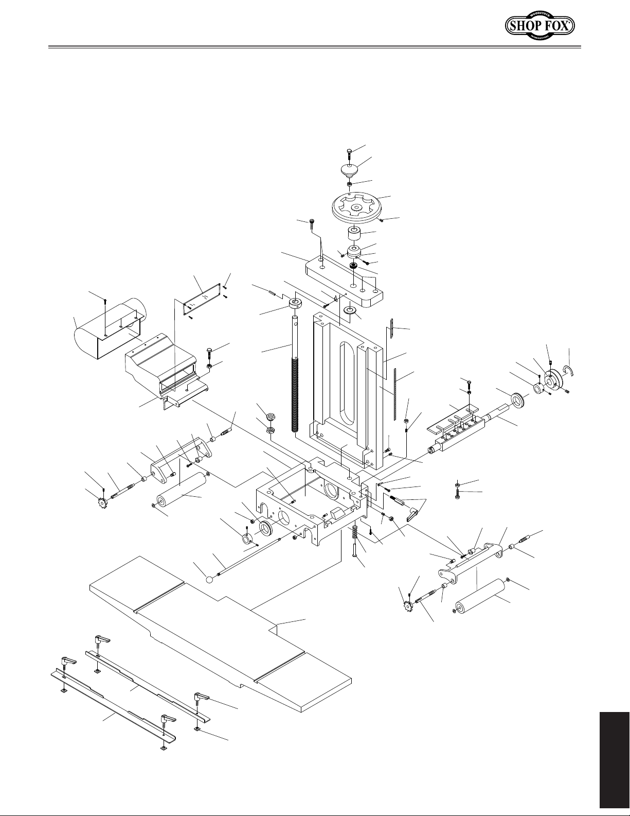
W1812 Owner's Manual (Mfd. Since 02/11)
Headstock
PARTS
4
5
9
6
30V2
34
33
92
35
36
31
38
39
62
93
80
61
56
36
37
23V2
57
98
95V2
32
7
40
25V2
3
14
41V2
8
11V2
19
43
2
42
18
15
24
97
68
13
63
59
33
10
91
16
7
65
17
64
34
60
39
1
10
28
69
36
46
62
71
70
23V2
25V2
88
61
87
47
8
37
21
26
93
36
20
22
40
29
10
1
90
12
44
45
27V2
73
72
83
84
PARTS
-45-
Page 49
W1812 Owner's Manual (Mfd. Since 02/11)
Headstock Parts List
REF PART # DESCRIPTION REF PART # DESCRIPTION
1 XPS07M PHLP HD SCR M4-.7 X 8 39 X1812039 SWING ARM AXIS SCREW
2 XPN06 HEX NUT 1/2-12 40 X1812040 DRIVEN AXLE
3 XPN05 HEX NUT 1/4-20 41V2 X1812041V2 HEAD CASTING V2.11.11
4 XPB25 HEX BOLT 3/8-16 X 1-3/4 42 X1812042 SWING ARM STOP PIN
5 X1812005 KNOB 43 X1812043 ROLLER PRESSURE SCREW
6 X1812006 HANDWHEEL 44 X1812044 COMPRESSION SPRING
7 XPN08 HEX NUT 3/8-16 45 X1812045 ROLLER PRESSURE PIN
8 XPSS11 SET SCREW 1/4-20 X 1/4 46 X1812046 INFEED DRIVE AXLE
9 XPN08 HEX NUT 3/8-16 47 X1812047 INFEED SWING ARM
10 XPSS08 SET SCREW 5/16-18 X 1/2 56 X1812056 KNOB 1/4-20
11V2 X1812011V2 TOP BRACE V2.12.10 57 X1812057 CHIP DEFLECTOR AXIS PIN
12 XPW14 FLAT WASHER 5/8 59 XPCAP03 CAP SCREW 5/16-18 X 1
13 XP51104 THRUST BEARING 51104 60 X1812060 BALL PLUNGER 3/8-16 X 3/4
14 XPRP73M ROLL PIN 4 X 30 61 X1812061 ECCENTRIC BUSHING
15 XPSS01 SET SCREW 5/16-18 X 1 62 XPFH12 FLAT HD SCR 1/4-20 X 1
16 X1812016 DOVETAILED COLUMN 63 XPS27 PHLP HD SCR 5/16-18 X 3/8
17 X1812017 SCALE 64 X1812064 POINTER
18 X1812018 SCALE COLLAR 65 X1812065 GIB
19 X1812019 ELEVATING SCREW 68 X1812068 SCALE ROLLER SCREW
20 XPSS02 SET SCREW 5/16-18 X 3/8 69 X1812069 PLANER KNIFE SET
21 X1812021 CUTTERHEAD PULLEY 70 XPW02 FLAT WASHER 3/8
22 X1812022 ROTATION LABEL 71 XPB18 HEX BOLT 3/8-16 X 1
23V2 X1812023V2 COLLAR V2.11.11 72 X1812072 INNER RAIL
24 X1812024 SPACER 73 X1812073 OUTER RAIL
25V2 XP6006-2RSNR BALL BEARING 6006-2RSNR W/SNAP RING 80 X1812080 WINDOW
26 X1812026 CUTTERHEAD 83 X1812083 T-NUT 1/4"-20
27V2 X1812027V2 TABLE V2.11.11 84 X1812084 ADJUSTABLE HANDLE
28 X1812028 LOCK LEVER ASSEMBLY 87 XPB03 HEX BOLT 5/16-18 X 1
29 XPCAP06 CAP SCREW 1/4-20 X 1 88 XPN02 HEX NUT 5/16-18
30V2 X1812030V2 DUST COVER V2.12.10 90 X1812090 POINTER
31 X1812031 CHIP DEFLECTOR 91 XPN02 HEX NUT 5/16-18
32 XPB18 HEX BOLT 3/8-16 X 1 92 XPFB05 FLANGE BOLT 10-24 X 1/2
33 X1812033 FEED ROLL SPROCKET 93 XPW07 FLAT WASHER 5/16
34 XPSS29 SET SCREW 10-24 X 1/4 95 X1812095 COLLAR V1
35 X1812035 OUTFEED DRIVE AXLE 95V2 X1812095V2 COLLAR V2.10.09
36 X1812036 NEEDLE BEARING 96 XPFB17 FLANGE BOLT 10-24 X 3/8
37 X1812037 RUBBER FEED ROLLER 97 X1812097 SCALE HUB
38 X1812038 OUTFEED SWING ARM 98 XPS06 PHLP HD SCR 10-24 X 3/8
PARTS
-46-
Page 50
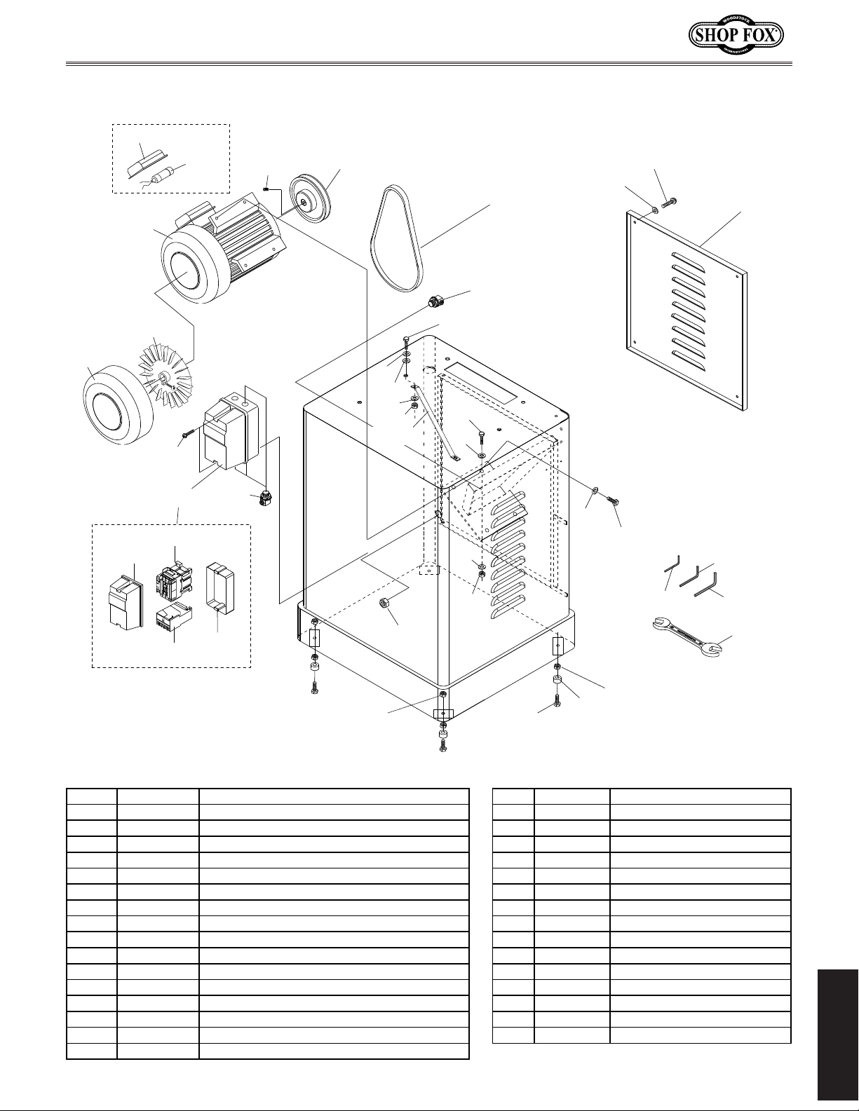
W1812 Owner's Manual (Mfd. Since 02/11)
217-1 X1812217-1 CONTACTOR SDE MA-09/15 220V
Main Motor & Cabinet
213-4
213
213-1V2
200
209
230
216-1
242
241
229V2
213-3
213-2
217-3
218
Add
217
217-1
217-2
216
217-4
211
244
211
240V2
210
207
216-1
210-1
210-2
211
211
207
221
211
220
208
210
250
251
252
253
REF PART # DESCRIPTION REF PART # DESCRIPTION
200 XPSS02 SET SCREW 5/16-18 X 3/8 217-2 X1812217-2 OL RELAY SDE RA-20 12-18A
207 XPN02 HEX NUT 5/16-18 217-3 X1812217-3 COVER
208 XPB07 HEX BOLT 5/16-18 X 3/4 217-4 X1812217-4 MAIN HOUSING
209 X1812209 MOTOR PULLEY 218 XPS22 PHLP HD SCR 10-24 x 5/8
210 XPN08 HEX NUT 3/8-16 220 X1812220 RUBBER FOOT
210-1 XPB03 HEX BOLT 5/16-18 X 1 221 XPB24 HEX BOLT 3/8-16 X 1-1/4
210-2 XPB12 HEX BOLT 5/16-18 X 1-1/4 229V2 X1812229V2 VENTED REAR PANEL V2.12.10
211 XPW07 FLAT WASHER 5/16 230 X1812230 LINK BELT 1/2 X 45"
213 X1812213 MOTOR 2HP 220V 240V2 X1812240V2 BRACKET V2.10.09
213-1V2 X1812213-1V2 S CAPACITOR 400M 125V 1-3/4 X 3-3/4 V2.02.11 241 XPW03 FLAT WASHER #10
213-2 X1812213-2 FAN 242 XPS08 PHLP HD SCR 10-24 X 3/4
213-3 X1812213-3 FAN COVER 244 X1812244 PLASTIC WASHER 5/16
213-4 X1812213-4 CAPACITOR COVER 250 XPAW02.5M HEX WRENCH 2.5MM
216 X1812216 STRAIN RELIEF 251 XPAW04M HEX WRENCH 4MM
216-1 X1812216-1 STRAIN RELIEF 252 XPAW05M HEX WRENCH 5MM
217 X1812217 MAGNETIC SWITCH ASSEMBLY MPE-09 253 XPWR1214 COMBO WRENCH 12/14MM
PARTS
-47-
Page 51
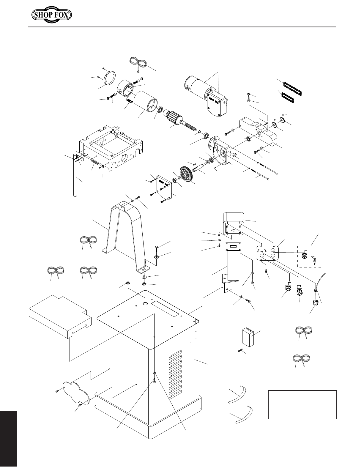
W1812 Owner's Manual (Mfd. Since 02/11)
Feed Motor & Controls
306
380
381
302-3
338
304
303V2
326V2
302-2
328
383
394
384
395
394
382
386
395
302-1V2
387
393
310
389
392
396
388
390
391
339
385
390
398
302-4
302
399
355
397
356
358
307
333
367
366
374
354
351
353
350
334
301
301
352
373
376V2
315-1V2
315V2
315-2V2
323
309
311
312
311
327
375
305V2
322
321
311
350
325
310-1
342-1
327
377
378
319
342
379V2
368V2
Note: For wiring
harness locations, refer
to wiring diagram on
Page 40.
340
310
311
PARTS
-48-
Page 52

W1812 Owner's Manual (Mfd. Since 02/11)
351 XPCAP159M CAP SCREW 1/4-20 X 2 399 XPRP44M ROLL PIN 3 X 10
Feed Motor & Controls Parts List
REF PART # DESCRIPTION REF PART # DESCRIPTION
301 X1812301 FEED ROLL SPROCKET 352 X1812352 CHAIN COVER
302 X1812302 FEED MOTOR 1/8 HP 220V 353 X1812353 INFEED ROLLER DRIVE CHAIN
302-1V2 X1812302-1V2 FEED MOTOR POWER CORD 18G 2C V2.12.10 354 X1812354 OUTFEED ROLLER DRIVE CHAIN
302-2 X1812302-2 FEED MOTOR BRUSH SET V1 355 XP6206-2RS BALL BEARING 6206 2RS
302-3 X1812302-3 PLASTIC LOCK SCREW V1 356 XPLW01M LOCK WASHER 5MM
302-4 X1812302-4 DRIVE GEAR V1 358 XP6082RS BALL BEARING 608-2RS
303V2 X1812303V2 STEEL CONDUIT V2.12.10 366 X1812366 CHAIN TENSIONER FOOT
304 X1812304 PLASTIC CONDUIT 367 XPN02 HEX NUT 5/16-18
305V2 X1812305V2 STAND V2.12.10 368V2 X1812368V2 CONSOLE CORD 18G 2C V2.12.10
306 XPS06 PHLP HD SCR 10-24 X 3/8 373 X1812373 KEYED POWER SWITCH
307 XPFH05 FLAT HD SCR 1/4-20 X 3/4 374 X1812374 CONTROL BOX
309 X1812309 GROMMET 30MM 375 X1812375 CONTROL BOX BRACKET
310 XPB07 HEX BOLT 5/16-18 X 3/4 376V2 X1812376V2 CONTROL PLATE V2.12.10
310-1 XPB03 HEX BOLT 5/16-18 X 1 377 X1812377 ON SWITCH
311 XPW07 FLAT WASHER 5/16 378 X1812378 OFF SWITCH
312 XPN02 HEX NUT 5/16-18 379V2 X1812379V2 CONTROL CORD 24G 4C V2.12.10
315-1V2 X1812315-1V2 CUTTERHEAD MOTOR CORD 14G 3C V2.12.10 380 XPS19M PHLP HD SCR M5-.8 X 6
315-2V2 X1812315-2V2 CONTROL PANEL CORD 18G 4C V2.12.10 381 X1812381 END CAP
315V2 X1812315V2 POWER CORD 14G 3C 6-15 V2.12.10 382 X1812382 BRUSH HOUSING
319 X1812319 VARIABLE SPEED CONTROL KNOB 383 X1812383 THERMOCOUPLE
321 X1812321 BOTTOM COLOR STRIPE 384 X1812384 STATOR HOUSING
322 X1812322 UPPER COLOR STRIPE 385 XPTLW08M EXT TOOTH WASHER 10MM
323 XPHTEK36 TAP SCREW #6 X 3/8 386 XP6200-2RS BALL BEARING 6200 2RS
325 XPB19 HEX BOLT 1/4-20 X 1/2 387 X1812387 ARMATURE
326V2 X1812326V2 PULLEY COVER V2.12.10 388 XPR06M EXT RETAINING RING 16MM
327 XPS06 PHLP HD SCR 10-24 X 3/8 389 XP6203-2RS BALL BEARING 6203-2RS
328 X1812328 CABLE CLAMPS 390 XP6202-2RS BALL BEARING 6202-ZZ
333 X1812333 MOTOR CASE SCREW M5-.8 X 133 391 X1812391 SHIM
334 XPSS29 SET SCREW 10-24 X 1/4 392 XPK34M KEY 5 X 5 X 20
338 XPW03 FLAT WASHER #10 393 X1812393 SPACER
339 XPN07 HEX NUT 10-24 394 XPLW01M LOCK WASHER 5MM
340 X1812340 SPEED CONTROL SWITCH 395 XPS20M PHLP HD SCR M5-.8 X 15
342 X1812342 CONSOLE UNIT 396 X1812396 COVER
342-1 XPHTEK28M TAP SCREW M4 X 25 397 X1812397 CASE
350 XPW06 FLAT WASHER 1/4 398 X1812398 GEAR SHAFT
-49-
PARTS
Page 53
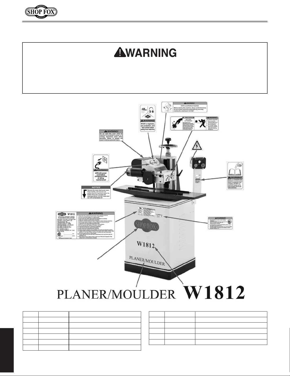
W1812 Owner's Manual (Mfd. Since 02/11)
REF PART # DESCRIPTION REF PART # DESCRIPTION
400 D3377 LOGO SHOP FOX 408 X1812408 MACHINE NAME LABEL
401 X1812401 COVER WARNING LABEL 409 XPLABEL-63 DISCONNECT 220V LABEL
402V2 X1812402V2 MACHINE ID LABEL-CSA V2.12.10 410 X1812410 MODEL NUMBER LABEL
404 X1812404 EYE/LUNG HAZARD LABEL 411 X1812411 DAMPNESS HAZARD LABEL
405 XLABEL-12 READ MANUAL LABEL 412 X1812412 MOTOR DUST LABEL
406 XLABEL-04 ELECTRICITY LABEL 413 X1812413 KNIFE CLEARANCE LABEL
407 X1812407 CUTTERHEAD WARNING LABEL
Label Placement
Safety labels warn about machine hazards and how to prevent machine damage or injury. The
owner of this machine MUST maintain the original location and readability of all labels on this
machine. If any label is removed or becomes unreadable, REPLACE that label before allowing the
machine to enter service again. Contact Woodstock International, Inc. at (360) 734-3482 or www.
shopfoxtools.com to order new labels.
413
412
400
402V2
409
401
404
407
406
405
411
408
PARTS
-50-
410
Page 54

W1812 Owner's Manual (Mfd. Since 02/11)
Warranty Registration
Name ___________________________________________________________________________________
Street __________________________________________________________________________________
City _________________________ State ___________________________ Zip ________________________
Phone # ______________________ Email___________________________Invoice # ___________________
Model #_________Serial #______________Dealer Name__________________Purchase Date___________
The following information is given on a voluntary basis. It will be used for marketing purposes to help us
develop better products and services. Of course, all information is strictly confidential.
1. How did you learn about us?
_____ Advertisement _____ Friend ____ Local Store
_____ Mail Order Catalog _____ Website ____ Other:
2. How long have you been a woodworker/metalworker?
_____ 0-2 Years _____ 2-8 Years ____ 8-20 Years _____ 20+ Years
3. How many of your machines or tools are Shop Fox?
_____ 0-2 _____ 3-5 ____ 6-9 _____ 10+
CUT ALONG DOTTED LINE
4. Do you think your machine represents a good value? _____ Yes ____ No
5. Would you recommend Shop Fox products to a friend? _____ Yes ____ No
6. What is your age group?
_____ 20-29 _____ 30-39 ____ 40-49
_____ 50-59 _____ 60-69 ____ 70+
7. What is your annual household income?
_____ $20,000-$29,000 _____ $30,000-$39,000 ____ $40,000-$49,000
_____ $50,000-$59,000 _____ $60,000-$69,000 ____ $70,000+
8. Which of the following magazines do you subscribe to?
____ Cabinet Maker
____ Family Handyman
____ Hand Loader
____ Handy
____ Home Shop Machinist
____ Journal of Light Cont.
____ Live Steam
____ Model Airplane News
____ Modeltec
____ Old House Journal
____ Popular Mechanics
____ Popular Science
____ Popular Woodworking
____ Practical Homeowner
____ Precision Shooter
____ Projects in Metal
____ RC Modeler
____ Rie
____ Shop Notes
____ Shotgun News
____ Today’s Homeowner
____ Wood
____ Wooden Boat
____ Woodshop News
____ Woodsmith
____ Woodwork
____ Woodworker West
____ Woodworker’s Journal
____ Other:
9. Comments: __________________________________________________________________
_____________________________________________________________________________
_____________________________________________________________________________
_____________________________________________________________________________
_____________________________________________________________________________
Page 55

FOLD ALONG DOTTED LINE
FOLD ALONG DOTTED LINE
Place
Stamp
Here
WOODSTOCK INTERNATIONAL INC.
P.O. BOX 2309
BELLINGHAM, WA 98227-2309
TAPE ALONG EDGES--PLEASE DO NOT STAPLE
Page 56

WARRANTY
WARRANTY
Woodstock International, Inc. warrants all Shop Fox machinery to be free of defects from workmanship
and materials for a period of two years from the date of original purchase by the original owner.
This warranty does not apply to defects due directly or indirectly to misuse, abuse, negligence or
accidents, lack of maintenance, or reimbursement of third party expenses incurred.
Woodstock International, Inc. will repair, replace, or arrange for a dealer refund at its expense and
at its option, the Shop Fox machine or machine part, which in proper and intended use has proven to
be defective, provided that the original owner returns the product prepaid to an authorized warranty
or repair facility as designated by our Bellingham, Washington office with proof of their purchase of
the product within two years, and provides Woodstock International, Inc. reasonable opportunity to
verify the alleged defect through inspection. If it is determined there is no defect, or that the defect
resulted from causes not within the scope of Woodstock International Inc.'s warranty, then the original
owner must bear the cost of storing and returning the product.
This is Woodstock International, Inc.’s sole written warranty and any and all warranties that may be
implied by law, including any merchantability or fitness, for any particular purpose, are hereby limited
to the duration of this written warranty. We do not warrant that Shop Fox machinery complies with
the provisions of any law, acts or electrical codes. We do not reimburse for third party repairs. In no
event shall Woodstock International, Inc.’s liability under this limited warranty exceed the purchase
price paid for the product, and any legal actions brought against Woodstock International, Inc. shall be
tried in the State of Washington, County of Whatcom. We shall in no event be liable for death, injuries
to persons or property or for incidental, contingent, special or consequential damages arising from the
use of our products.
Every effort has been made to ensure that all Shop Fox machinery meets high quality and durability
standards. We reserve the right to change specifications at any time because of our commitment to
continuously improve the quality of our products.
Page 57

 Loading...