

Page 1
Model W1676
REF PART�# DESCRIPTION
114A X1676114A IDLER�ROLLER�GUARD�V2.03.08
114A-1 X1676114A-1 SLEEVE
�GUARD
128 X1676128 LOCK
�KNOB
129 PW03 FLAT
�WASHER�#10
COMBINATION SANDER
MANUAL UPDATE
This update covers changes made to the machine after the owner's manual was printed. All page number
references refer to the owner's manual for this machine. Keep this update with your owner's manual for
future reference.
If you have questions, contact Tech Support at (360) 734-3482 or by email at
.
What Changed?
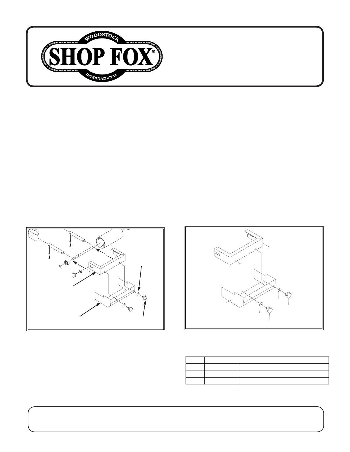
We added a sleeve guard to the sander to help
reduce the risk of entanglement. The sleeve
guard MUST be installed on the idler roller
guard, using the included lock knobs and flat
washers, as shown in Figure
Install the idler roller guard and sleeve guard
onto the idler roller after belt tension and track
ing are properly set, as described in the Model
W1676 Manual on Pages 18 & 19
Idler Roller
Guard
1.
.
#10 Flat
Washer
Machine Inventory (See Page 11)
The following items have been added. Refer to
the full manual for a description of all other
inventory components.
Box Contents
: Qty
A. Sleeve Guard .................................. 1
B. Lock Knobs ..................................... 2
-
C. Flat Washers #10 .............................. 2
New Sleeve Guard Parts
Sleeve Guard
Figure 1. Installing sleeve guard.
COPYRIGHT © M ARCH, 2008 BY WOODSTOCK INTERNATIONA L, INC.
WARN ING : N O PO RTION OF THI S MANU AL MAY BE REP ROD UCED I N ANY S HAPE O R FORM WITHOUT
THE W RITTE N AP PROVA L OF WO ODSTOCK I NTERN ATI ONAL, INC.
Lock Knob
Figure 2. New sleeve guard parts.
Prin ted in Tai wan#106 09B L
Page 2

INSTRUCTION MANUAL
MODEL W1676
COMBINATION SANDER
Phone: 1-360-734-3482 • On-Line Technical Support: [email protected]
COPYRIGHT © 2001 BY WOODSTOCK INTERNATIONAL, INC.
WARNING: NO PORTION OF THIS MANUAL MAY BE REPRODUCED IN ANY SHAPE OR FORM WITHOUT
THE WRITTEN APPROVAL OF WOODSTOCK INTERNATIONAL, INC.
Printed in Taiwan
Page 3

WARNING
Some dust created by power sanding, sawing, grinding, drilling, and other construction activities contains chemicals known to the State of California to
cause cancer, birth defects or other reproductive
harm. Some examples of these chemicals are:
• Lead from lead-based paints.
• Crystalline silica from bricks, cement, and
other masonry products.
• Arsenic and chromium from chemically
treated lumber.
Your risk from these exposures varies, depending on
how often you do this type of work. To reduce your
exposure to these chemicals: work in a well ventilated area, and work with approved safety equipment, such as those dust masks that are specially
designed to filter out microscopic particles.
Page 4

-1-
Table Of Contents
PAGE
1. INTRODUCTION ....................................................................................2
ABOUT YOUR NEW SANDER..................................................................2
WOODSTOCK SERVICE AND SUPPORT......................................................2
WARRANTY AND RETURNS ..................................................................3
MACHINE SPECIFICATIONS ..................................................................3
2. SAFETY..............................................................................................4
SAFETY FIRST................................................................................4-5
SANDER SAFETY................................................................................6
110V ELECTRICAL REQUIREMENTS ........................................................7
220V ELECTRICAL REQUIREMENTS ........................................................8
AVOIDING POTENTIAL INJURIES ............................................................9
3. ASSEMBLY INSTRUCTIONS......................................................................10
UNPACKING ..............................................................................10-11
CLEAN UP......................................................................................12
GENERAL ......................................................................................13
SANDING UNIT TO BASE ....................................................................14
IDLER ROLLER ................................................................................14
SANDING DISC ................................................................................14
BACK STOP ....................................................................................15
DUST PORTS ..................................................................................15
WORKING TABLE ............................................................................16
QUICK RELEASE ..............................................................................16
4. ADJUSTMENTS....................................................................................17
GENERAL ......................................................................................17
BELT TRACKING/TENSION ..............................................................18-19
IDLER GUARD ................................................................................19
VERTICAL POSITIONING ....................................................................20
CHANGING DISC ABRASIVE..................................................................21
TABLE TILT....................................................................................22
5. OPERATIONS......................................................................................23
TESTING........................................................................................23
HORIZONTAL SANDING ....................................................................24
CURVED SANDING ............................................................................24
DISC SANDING ................................................................................25
6. MAINTENANCE....................................................................................26
GENERAL ......................................................................................26
TABLE AND BASE ............................................................................26
LUBRICATION ................................................................................26
7. CLOSURE ..........................................................................................27
8. WIRING DIAGRAM ................................................................................28
PARTS BREAKDOWN AND PARTS LISTS..................................................29-32
USE THE QUICK GUIDE PAGE LABELS TO SEARCH OUT INFORMATION FAST!
Page 5

-2-
INTRODUCTION
ABOUT YOUR NEW SANDER
This new Shop Fox®W1676 Sander has been specially designed to provide many years of trouble-free service. Close attention to detail, ruggedly built parts and a rigid quality control program assure safe and
reliable operation.
The Model W1676 is capable of a wide variety of sanding operations. The 6" wide belt can quickly sand
large surfaces flat and the 10" sanding disc and adjustable table can sand many different angles. The
combination sander comes with a cabinet-style stand, miter gauge, 1 H.P. motor, sanding belt and disc,
and electrical package.
Woodstock International, Inc. is committed to customer satisfaction in providing this manual. It is our
intent to make sure all the information necessary for safety, ease of assembly, practical use and durability of this product be included.
If you should have any comments regarding this manual, please feel free to contact us at:
WOODSTOCK SERVICE AND SUPPORT
We stand behind our machines! In the event that a defect is found, parts are missing or questions arise
about your machine, please contact Woodstock International Service and Support at 1-360-734-3482 or
send e-mail to: [email protected]
. Our knowledgeable staff will help you troubleshoot
problems, send out parts or arrange warranty returns.
Woodstock International, Inc.
Attn: Technical Department
P.O. Box 2309
Bellingham, WA 98227
Page 6

-3-
WARRANTY AND RETURNS
Woodstock International, Inc. warrants all SHOP FOX®machinery to be free of defects from workmanship and materials for a period of 2 years from the date of original purchase by the original owner. This
warranty does not apply to defects due directly or indirectly to misuse, abuse, negligence or accidents,
lack of maintenance, or to repairs or alterations made or specifically authorized by anyone other than
Woodstock International, Inc.
Woodstock International, Inc. will repair or replace, at its expense and at its option, the SHOP FOX
®
machine or machine part which in normal use has proven to be defective, provided that the original
owner returns the product prepaid to the SHOP FOX
®
factory service center or authorized repair facility
designated by our Bellingham, WA office, with proof of their purchase of the product within 2 years, and
provides Woodstock International, Inc. reasonable opportunity to verify the alleged defect through
inspection. If it is determined there is no defect, or that the defect resulted from causes not within the
scope of Woodstock International Inc.'s warranty, then the original owner must bear the cost of storing
and returning the product.
This is Woodstock International, Inc.'s sole written warranty and any and all warranties that may be
implied by law, including any merchantability or fitness, for any particular purpose, are hereby limited
to the duration of this written warranty. We do not warrant that SHOP FOX
®
machinery complies with
the provisions of any law or acts. In no event shall Woodstock International, Inc.'s liability under this warranty exceed the purchase price paid for the product, and any legal actions brought against Woodstock
International, Inc. shall be tried in the State of Washington, County of Whatcom. We shall in no event
be liable for death, injuries to persons or property or for incidental, contingent, special or consequential damages arising from the use of our products.
Every effort has been made to ensure that all SHOP FOX
®
machinery meets high quality and durability
standards. We reserve the right to change specifications at any time because of our commitment to continuously improve the quality of our products.
Machine Specifications
Motor Size: ......................................................1 H.P., 110/220V Single-Phase
Motor Speed ............................................................................3450 R.P.M.
Amps..............................................................................................14/7
Sanding Belt..................................................................................6" x 48"
Belt Speed ..............................................................................1900 F.P.M.
Sanding Disc ......................................................................................10"
Disc Speed ..............................................................................2420 R.P.M.
Table (Disc) ..............................................................................6" x 12
1
⁄4"
Stand ......................................................Cabinet Style, Powder Coated Paint
Power Transfer ................................................................Belt Drive (3L-240)
Bearings ....................................................Shielded & Lubricated Ball Bearings
Switch ............................................Paddle ON/OFF Switch, w/ Safety Lock Key
Shipping Weight ............................................................................170 lbs.
Page 7

-4-
READ MANUAL BEFORE OPERATING MACHINE.
FAILURE TO FOLLOW INSTRUCTIONS BELOW WILL
RESULT IN PERSONAL INJURY.
SAFETY FIRST!
1. Thoroughly read the instruction manual before operating your machine. Learn the applications,
limitations and potential hazards of this machine. Keep manual in a safe, convenient place for future
reference.
2. Keep work area clean and well lighted. Clutter and inadequate lighting invite potential hazards.
3. Ground all tools. If a machine is equipped with a three-prong plug, it must be plugged into a three-
hole grounded electrical outlet or grounded extension cord. If using an adapter to aid in accommodating a two-hole receptacle, ground using a screw to a known ground.
4. Wear eye protection at all times. Use safety glasses with side shields or safety goggles that meet
the national safety standards, while operating this machine.
5. Avoid dangerous environments. Do not operate this machine in wet or open flame environments.
Airborne dust particles could cause an explosion and severe fire hazard.
6. Ensure all guards are securely in place and in working condition.
7. Make sure switch is in the “OFF” position before connecting power to machine.
8. Keep work area clean, free of clutter, grease, etc.
9. Keep children and visitors away. Visitors should be kept a safe distance away while operating unit.
10. Childproof workshop with padlocks, master switches or by removing starter keys.
11. Disconnect machine when cleaning, adjusting or servicing.
Indicates an imminently hazardous situation which, if not avoided, WILL
result in death or serious injury.
Indicates a potentially hazardous situation which, if not avoided, COULD
result in death or serious injury.
Indicates a potentially hazardous situation which, if not avoided, MAY
result in minor or moderate injury. It may also be used to alert against
unsafe practices.
This symbol is used to alert the user to useful information about proper
operation of the equipment.
NOTICE
Page 8
-5-
12. Do not force tool. The machine will do a safer and better job at the rate for which it was designed.
13. Use correct tool. Do not force machine or attachment to do a job for which it was not designed.
14. Wear proper apparel. Do not wear loose clothing, neck ties, gloves, jewelry, keep long hair tied up,
etc.
15. Remove adjusting keys and wrenches. Before turning the machine on, make it a habit to check that
all adjusting keys and wrenches have been removed.
16. Use proper extension cord. When using an extension cord, make sure it is less than 100' in length
and that it is in good condition. Use extension cords that are rated Hard Service (grade S) or better,
and that have a conductor size of 16 A.W.G. A drop in line voltage, loss of power and overheating
can result when using an undersized cord. The extension cord should have a ground wire and ground
plug pin, as well.
17. Keep proper footing and balance at all times.
18. Do not leave machine unattended. Wait until it comes to a complete stop before leaving the area.
19. Perform machine maintenance and care. Follow lubrication and accessory attachment instructions
in the manual.
20. Keep machine away from open flame. Operating machines near pilot lights and/or open flames cre-
ates a high risk if dust is dispersed in the area. Dust particles and an ignition source may cause an
explosion. Do not operate the machine in high-risk areas, including but not limited to, those mentioned above.
21. If at any time you are experiencing difficulties performing the intended operation, stop using the
machine! Then contact our service department or ask a qualified expert how the operation should
be performed.
22. Habits—good and bad—are hard to break. Develop good habits in your shop and safety will become
second-nature to you.
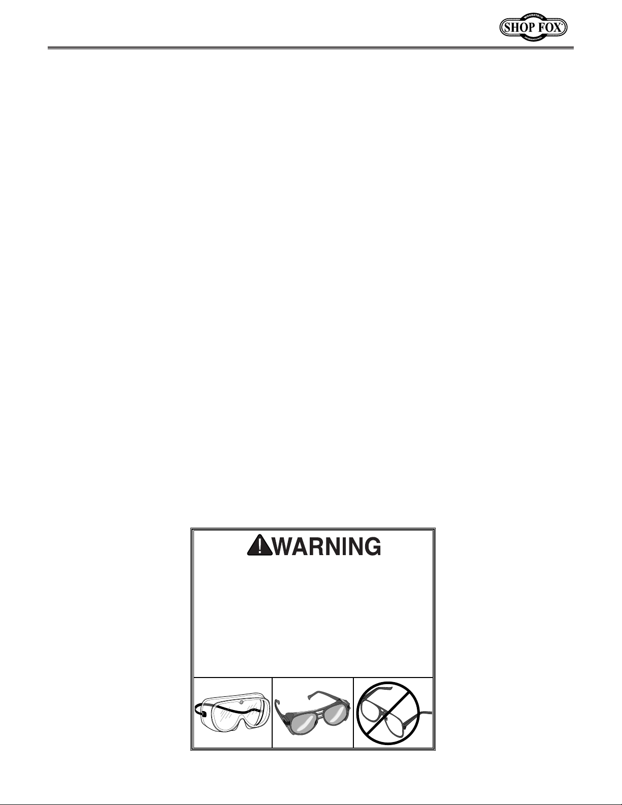
Operating this equipment creates the potential for flying debris to cause eye injury.
Always wear safety glasses or goggles when
operating equipment. Everyday glasses or
reading glasses only have impact resistant
lenses, they are not safety glasses. Be certain the safety glasses you wear meet the
appropriate standards of the American
National Standards Institute (ANSI).
Page 9
-6-
Additional Safety Instructions For Sanders
1. Be aware of belt or disc rotation when sanding. Always brace workpiece against the rotation of the
sanding belt. Always sand on the side of the disc that is rotating downward, towards the work table.
2. Keep fingertips away from the moving belt or disc.
3. Never use excessive force when sanding. Doing this greatly increases the chances of personal injury
and motor overload.
4. Always feed the work against the direction of rotation.
5. Even if you have a reliable method of dust collection, use a dust mask or respirator when sanding,
as well as eye and ear protection.
6. If there is any doubt as to the stability or integrity of the material to be sanded, do not sand it.
7. Do not operate sander with a damaged or badly worn disc or belt.
8. Habits — good or bad — are hard to break. Develop good habits and safety will become second
nature to you.
9. Sanding dust from some woods may be toxic or cause an allergic reaction. Be sure to wear an
appropriate respirator when working around saw dust. Make sure there is adequate ventilation or a
constant source of fresh air. The saw dust from some species of wood can be toxic to some people.
Be sure to research the dangers of the specific species of wood you are working with.
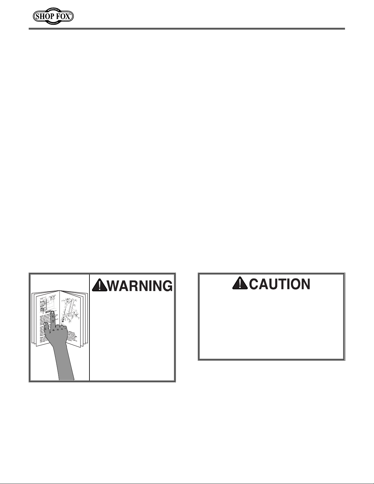
Read the manual before
assembly and operation.
Become familiar with
the machine and its
operation before beginning any work. Serious
personal injury may
result if safety or operational information is not
understood or followed.
No list of safety guidelines can be complete.
Every shop environment is different. Always
consider safety first, as it applies to your
individual working conditions. Use this and
other machinery with caution and respect.
Failure to follow guidelines could result in
serious personal injury, damage to equipment or poor work results.
Page 10
-7-
110V Operation
ELECTRICAL REQUIREMENTS
When it is necessary to use an extension cord,
use the following guidelines:
•Use cords rated for Hard Service (Grade S)
•Never exceed a length of 100 feet
•Use cords with 14 ga. wire or bigger
(12 ga., 10 ga., etc.)
•Ensure cord has a ground wire and pin
•Do not use cords in need of repair
Extension Cords
Grounding
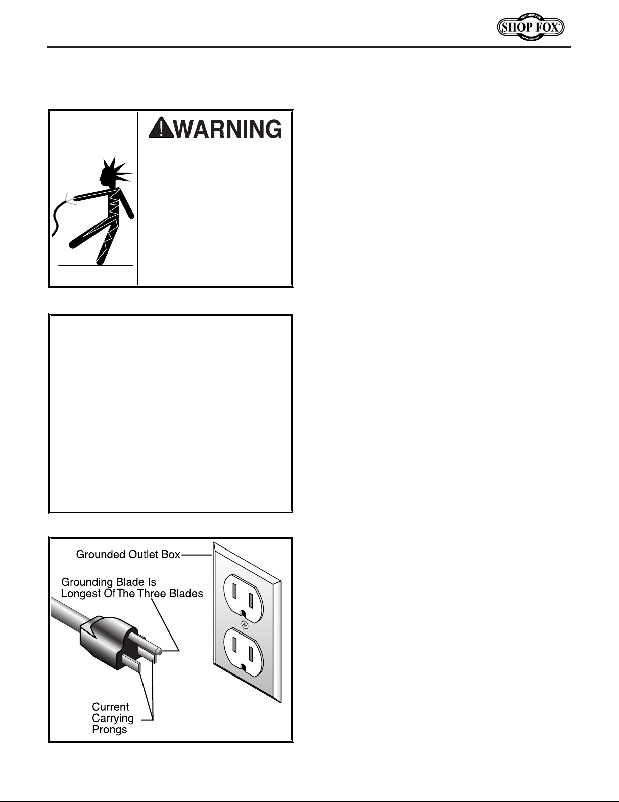
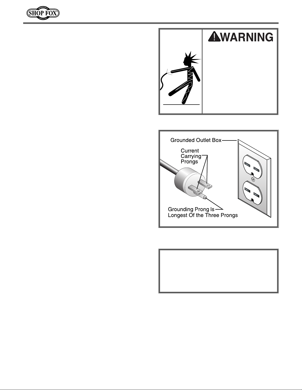
This machine must be grounded! See Figure 1A.
The electrical cord supplied with the W1676
comes with a grounding pin. Do not remove it.
If your outlet does not accommodate a ground
pin, have it replaced by a qualified electrician
or have an appropriate adapter installed. Please
note: when using an adapter, the adapter must
be grounded.
An adapter with a grounding wire does not guarantee machine will be grounded. Ground source
must be verified.
The Shop Fox
®
W1676 is prewired for 110 volts.
The motor supplied with your new machine is
rated at 1 H.P. and will draw approximately 14
amps. When choosing an outlet for this machine,
consider using one with a 15 amp circuit breaker or fuse. Keep in mind that a circuit being used
by other machines or tools at the same time will
add to the electrical load being applied to the
circuit. Add up the load ratings of all machines
on the circuit. If this number exceeds the rating
of the circuit breaker or fuse, use a different
circuit.
Figure 1A. Typical 110V 3-prong plug and outlet.
Figure 1. Never remove grounding pin.
This equipment must be
grounded. Verify that any
existing electrical outlet
and circuit you intend to
plug into is actually grounded. Under no circumstances
should the grounding pin
from any three-pronged
plug be removed. Serious
injury may occur.
Page 11
-8-
Figure 2. NEMA-style 6-15 plug and outlet.
NOTICE
Never replace the circuit breaker with one
rated at a higher amperage or damage to the
circuit may occur.
This equipment must be
grounded. Verify that any
existing electrical outlet
and circuit you intend to
plug into is actually grounded. Under no circumstances
should the grounding pin
from any three-pronged
plug be removed. Serious
injury may occur.
220V Operation
We do not recommend using an extension cord
for 220V equipment. Instead, arrange the placement of your machinery and installed wiring to
eliminate the need for extension cords. If you
must use an extension cord, make sure it is
rated Hard Service (grade S) or better. The
extension cord must always contain a ground
wire and plug pin. Always repair or replace
extension cords when they become worn or
damaged.
Extension Cords
Grounding
This machine must be grounded! See Figure 2.
The electrical cord supplied with the W1676
does not come with a 220 volt plug. Use a plug
with a ground pin. If your outlet does not
accommodate a ground pin, have it replaced by
a qualified electrician or have an appropriate
adapter installed and grounded properly. An
adapter with a grounding wire does not guarantee machine will be grounded. Ground source
must be verified.
The Shop Fox
®
W1676 can also be operated at
220 volts. To do this, consult with the wiring
diagram in the back of this manual for rewiring
instructions. Also, you will need a NEMA-style 615 plug and outlet.
The motor supplied with your new machine is
rated at 1 H.P. and will draw approximately 7
amps during 220 volt operation. When choosing
an outlet for this machine, consider using one
with a 15 amp circuit breaker or fuse. Keep in
mind that a circuit being used by other machines
or tools at the same time will add to the total
load being applied to the circuit. Add up the
load ratings of all machines on the circuit. If this
number exceeds the rating of the circuit breaker or fuse, use a different circuit.
Page 12

-9-
AVOIDING POTENTIAL INJURIES
Figure 3. Never place fingers close to moving disk.
Figure 4. Never use the right side of disk.
Upward rotation of disk can propel workpiece
into the air.
Figure 6. Never place hands near back stop.
On small workpieces always use push blocks.
Figure 5. Always unplug sander when adjusting.
Page 13
-10-
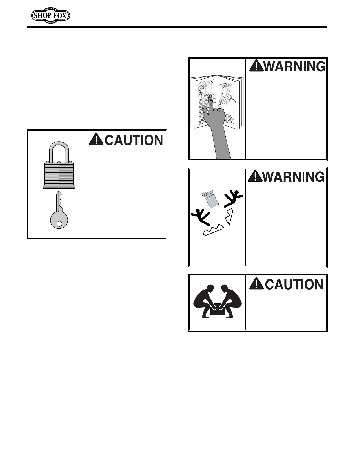
Read the manual before
assembly and operation.
Become familiar with
the machine and its
operation before beginning any work. Serious
personal injury may
result if safety or operational information is not
understood or followed.
If moving this machine up
or down stairs, the
machine must be dismantled and moved in smaller pieces. Make sure
floor and stair structures
are capable of supporting
the combined weight of
the machine parts and
the people moving them.
The W1676 represents a
heavy load at 170
pounds. Seek assistance
before beginning assembly.
ASSEMBLY INSTRUCTIONS
Unpacking
The Model W1676 has been carefully packaged
for safe transporting. If you notice the machine
has been damaged or is missing any parts,
please contact the store where you purchased
the machine.
Make your shop “child
safe.” Ensure that your
workplace is inaccessible to youngsters by
closing and locking all
entrances when you are
away. Never allow visitors in your shop when
assembling, adjusting
or operating equipment.
Page 14

-11-
The following is a description of the components
shipped with the Shop Fox
®
W1676. It is recom-
mended that the components be laid out in a similar fashion to those in Figures 7 and 8. This will
help in identification before beginning assembly.
Should any part be missing, examine the packaging carefully. If any key parts are missing, call
Woodstock International, Inc. at 360-734-3482 or
e-mail: [email protected]
.
1. Sanding Unit 1
2. Sanding Belt 1
3. Sanding Disc 1
4. Cast Iron Disc 1
5. Idler Roller 1
6. Back Stop 1
7. Miter Gauge 1
8. Work Table 1
9. Table Support Rod 1
10. Quick Release Handle 1
11. Dust Port 1
12. Idler Roller Guard 1
13. Bolt Bag 1
14. 2
1
⁄2" Dia. Dust Port 1
15. Cabinet Stand 1
Item QTY.
Figure 7. Stand and sanding unit.
Figure 8. Component layout.
Contents of the Bolt Bag
QTY. DESCRIPTION
LOCATION
4
5
⁄16''-18 x 1⁄2'' Hex Bolts
Stand/Base
4
5
⁄16'' Flat Washers
Stand/Base
4
5
⁄16''-18 x 1'' Hex Bolts
Stand /Feet
4
5
⁄16'' Flat Washers
Stand /Feet
4
5
⁄16''-18 Hex Nuts
Stand /Feet
4
3
⁄16" Phillips®Screws Dust Port
4
3
⁄16" Washers Dust Port
4
3
⁄16" Hex Nuts Dust Port
1 Long 4mm Allen® Wrench
4 Rubber Feet Stand /Feet
1
34
5
6
7
8
9
10
14
15
11
12
13
2
Page 15
-12-
Clean Up
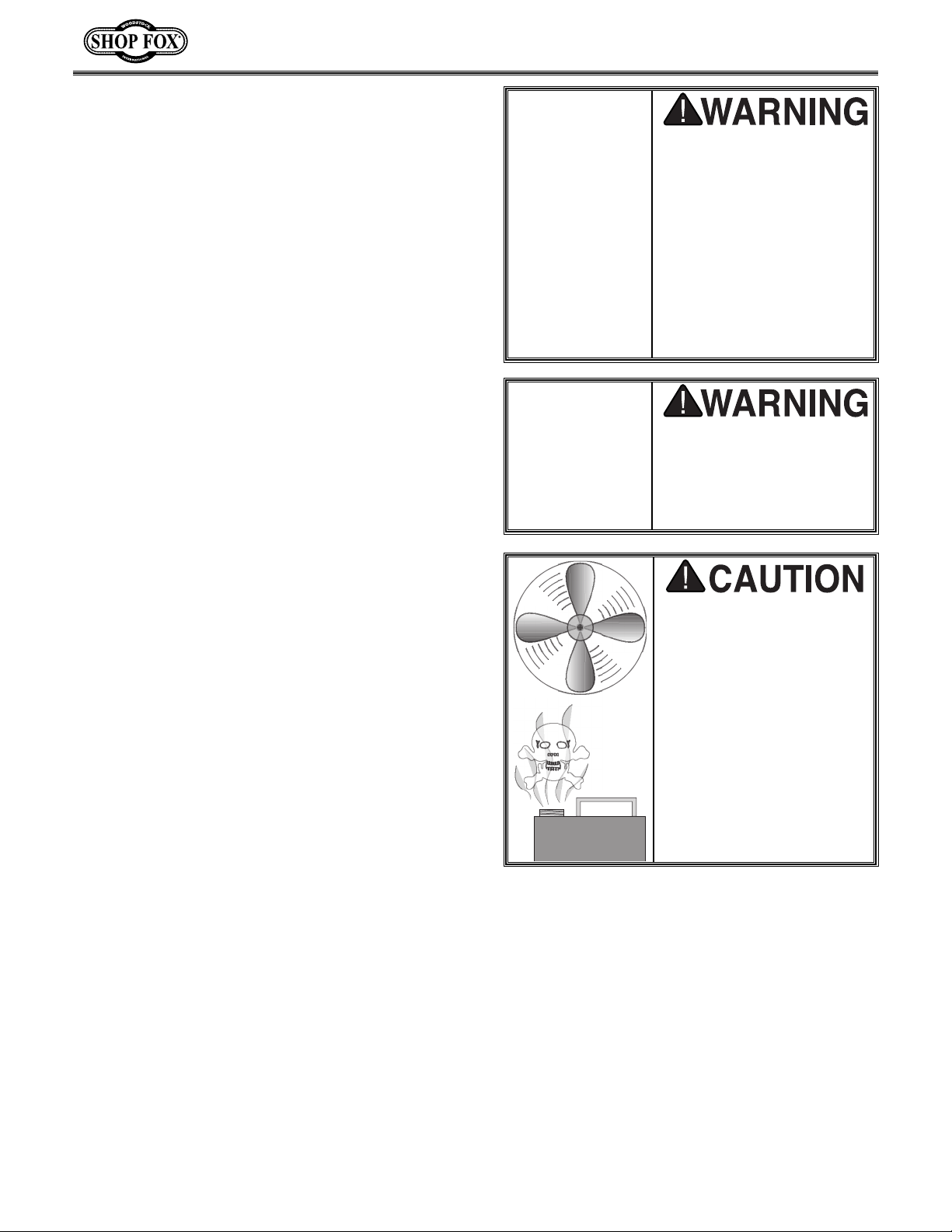
Do not use gasoline or
other petroleum-based
solvents. They have low
flash points which make
them extremely flammable. A risk of explosion
and burning exists if these
products are used.
Serious personal injury
may occur if this warning
is ignored.
Do not smoke while using
solvents. A risk of explosion or fire exists and may
result in serious personal
injury.
The exposed, unpainted surfaces of the machine
have been coated with an oil to prevent rust
during shipment. This oil needs to be removed
before operation. To remove the oil, we recommend using a solvent based degreaser. Avoid
using any chlorine based solutions because they
will damage the painted surfaces. Always follow
the instructions of the product being used.
Many of the solvents commonly used to clean
machinery can be toxic
when inhaled or ingested.
Always work in well-ventilated areas far from
potential ignition sources
when dealing with solvents. Use care when disposing of waste rags and
towels to be sure they do
not create fire or environmental hazards.
Page 16
-13-
General
While the main components of the Shop Fox
®
W1676 are assembled at the factory, some
assembly is required. The following is the recommended sequence best suited for final
assembly.
TOOLS REQUIRED (NOT INCLUDED): You will
need a 6" adjustable wrench, 12mm open-end
wrench, flathead screwdriver, Phillips
®
screw-
driver and 4mm Allen
®
wrench.
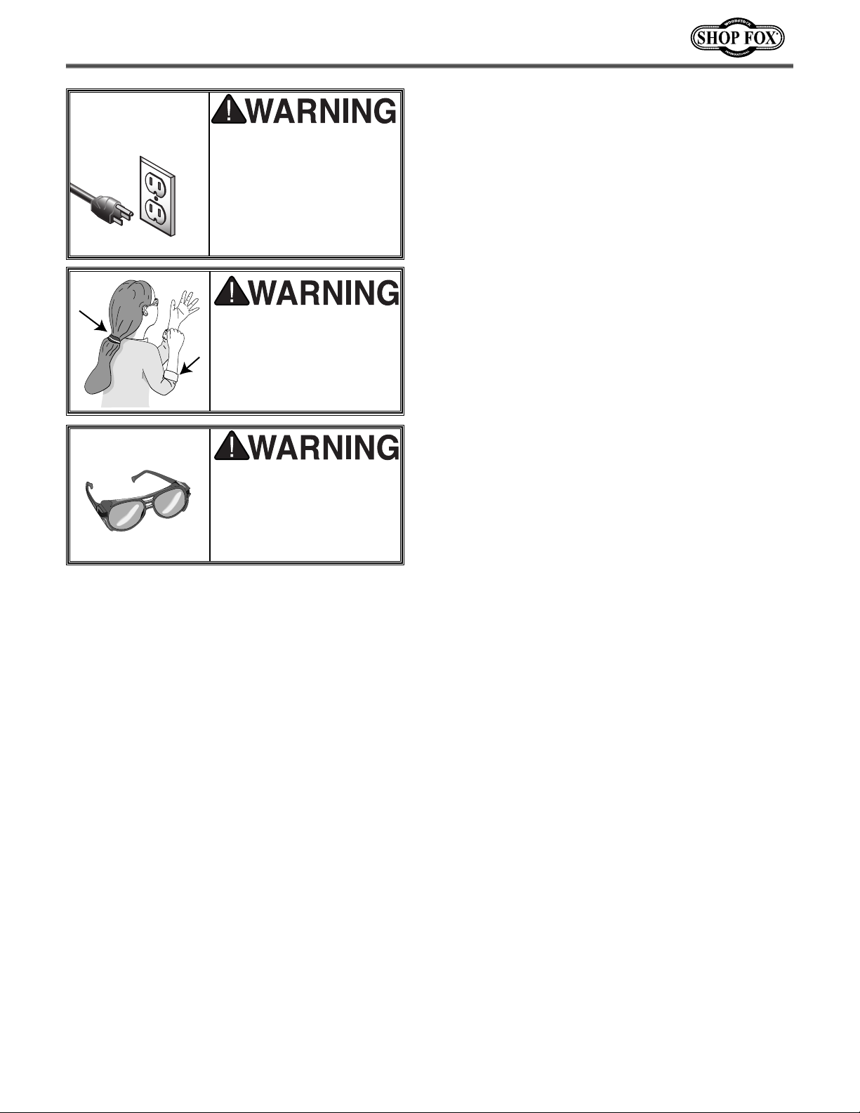
Wear safety glasses during the entire assembly
process. Failure to comply may result in serious
personal injury.
Keep loose clothing
rolled up and out of the
way of machinery and
keep hair pulled back.
Disconnect power to the
machine when performing any maintenance,
assembly or adjustments. Failure to do this
may result in serious
personal injury.
!
Page 17
-14-
Sanding Unit To Base
The Model W1676 comes with a prefabricated
welded steel stand that requires no assembly.
However, the sanding unit needs to be mounted
to the stand.
1. With the help of a friend, lift the main sand-
ing unit on top of the steel stand.
2. Align the four mounting holes in the stand
with the slots on the bottom corners of the
sanding unit as shown in Figure 9.
3. Using (4)
5
⁄16"-18 x 1⁄2" hex bolts, 5⁄16" wash-
ers and
5
⁄16" nuts, fasten the sanding unit to
the stand.
Idler Roller
Install the idler roller by inserting its flat axle
ends into the slots on the ends of the adjustments bar as shown in Figure 10.
Sanding Disc
The sanding disc is installed onto the keyed
drive shaft using a
5
⁄16"-18 x 3⁄8" setscrew as
shown in Figure 11. For clearance purposes, we
have included a long shaft 4mm Allen
®
wrench.
Figure 9. Stand mounting holes.
Figure 10. Idler roller.
Figure 11. Installing sanding disk.
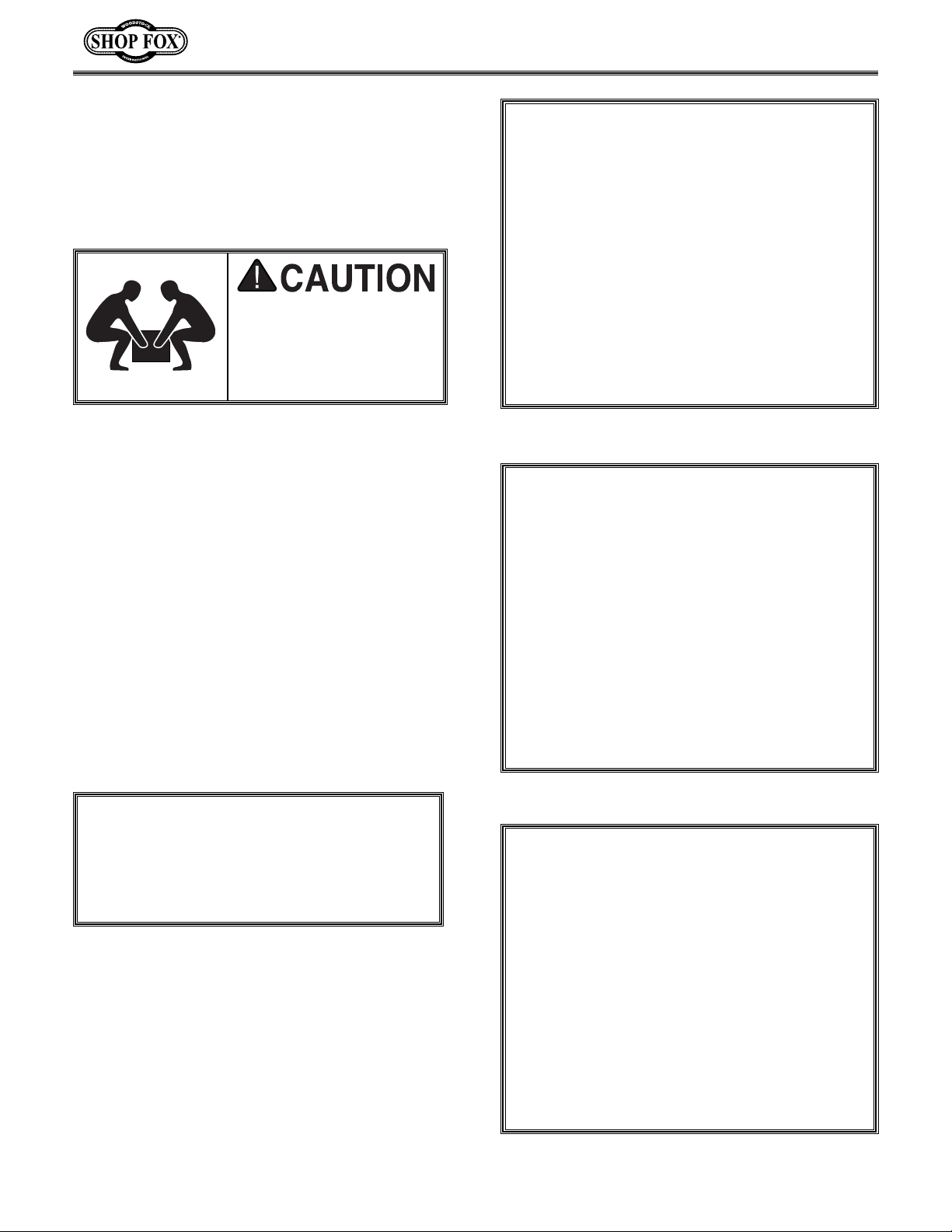
The W1676 represents a
heavy load at 170
pounds. Seek assistance
before beginning assembly.
NOTICE
Until the sanding belt is installed, along
with the idler guard, the idler roller can
fall off causing damage.
Page 18
-15-
Back Stop
The back stop serves as a resting point for the
workpiece while flat sanding on the belt. Install
the back stop to the sanding belt frame using a
5
⁄16"-18 x 1" hex bolt and a 5⁄16" flat washer as
shown in Figure 12. The back stop can be
removed when sanding long workpieces.
Dust Ports
The dust ports are designed to reduce the
amount of dust on the sander and in the air.
Fasten the belt dust port to the sanding belt
frame using (2) Phillips
®
head screws as shown
in Figure 13. Fasten the disc dust port using (4)
Phillips
®
head screws and nuts as shown in
Figure 14.
Figure 12. Installing back stop.
Figure 13. Installing dust port.
Figure 14. Disc sanding dust port.
Always wear a dust mask
when operating the
W1676. Using this
machine produces sawdust which may cause
allergic reactions or respiratory problems.
Page 19
-16-
Working Table
The working table has two mounting locations:
next to the sanding disc and next to the vertically positioned belt sander. We recommend initially mounting the working table next to the
disc. If you want to mount it next to the vertically positioned belt sander, skip to the
“Vertical Positioning” instructions in the
Adjustment section.
To install the working table next to the disc:
1. Loosen the (2)
5
⁄16"-18 x 3⁄8" setscrews located in the base, directly beneath the pulley
cover.
2. Insert the support bar into the hole in the
base that is adjacent to the setscrew holes.
Make sure that the flat side of the support
bar is facing the setscrews.
3. Securely tighten the setscrews as shown in
Figure 15.
4. Slide the working table assembly onto the
end of the support bar and securely tighten
the setscrews located in the table support
bracket as shown in Figure 16. Be sure to
leave no more than a
1
⁄16" gap between the
disc and the edge of the working table.
Quick Release
The quick release lever is used to loosen the
tension on the sanding belt. To install the quick
release lever:
1. Thread a
3
⁄8"-16 hex nut on each end of the
quick release levers.
2. Thread the ends of the levers into the
threaded holes in the short lever and the
rocker arm.
3. Finally, position the levers as shown in
Figure 17 and tighten down the hex nuts.
Figure 15. Tightening the setscrews.
Figure 16. Tightening the setscrews.
Figure 17. Installing the quick release.
Rocker Arm
Short Lever
Page 20
-17-
ADJUSTMENTS
General
The Model W1676 is capable of a wide variety of
sanding operations. The sanding belt can be
positioned in a variety of angles ranging from 090° and can accommodate the working table in
the vertical position. The sanding disc can
accommodate the working table at a variety of
angles ranging from 0-45°. In all, the Model
W1676 will be a welcome addition to the home
or commercial workshop. The following section
will go through the above adjustment steps.
Wear safety glasses during the entire adjustments process. Failure to
comply may result in
serious personal injury.
Keep loose clothing
rolled up and out of the
way of machinery and
keep hair pulled back.
Disconnect power to the
machine when performing any maintenance,
assembly or adjustments. Failure to do this
may result in serious
personal injury.
!
Page 21
-18-
Belt Tracking/Tension
Belt tension and tracking are crucial to the performance of the belt sander. Too much tension
will cause undue stress on the bearings and
other parts. Too little tension will cause the
sanding belt to not track properly and fall off
the sanding belt frame. It is better to have the
least amount of tension required to make the
belt track properly while under load.
To adjust the tracking:
1. Unplug the combination sander!
2. Unlock the quick release lever on the side of
the sanding unit by shifting it to the left.
3. Slide a 6" x 48" sanding belt onto the belt
sanding frame as shown in Figure 18.
4. Shift the quick release lever to the right to
tension the sanding belt.
5. To check the tracking, plug in and quickly
turn the sander on and off, and watch the
path of the belt. If it moves to either side,
the tracking needs to be adjusted.
6. Turn the tracking knob
1
⁄4 turn clockwise to
adjust the sanding belt towards the tracking
knob, and turn counter-clockwise to adjust
the sanding belt away from the tracking
knob as shown in Figure 19.
7. Quickly turn the machine on and off again to
see if the tracking has improved. If not,
repeat the above steps.
8. If the tracking is fairly well maintained,
leave the machine running and fine tune the
sanding belt by further adjusting the tracking knob.
Figure 18. Installing the sanding belt.
Figure 19. Knob for adjusting tracking.
NOTICE
It is best to adjust the tracking of the sanding
belt before making any tension adjustments.
If you have trouble maintaining proper tracking after several attempts, you may need to
adjust the belt tension. Improper tension can
often times be the cause of tracking problems.
Always install belt according to the arrow
direction on the inside of the belt. Belts
installed incorrectly can fall apart, causing
serious personal injury.
Page 22

-19-
Belt Tracking/Tension
Continued
Gauging proper belt tension is very subjective.
The easiest way to check the tension is to pluck
the edge of the sanding belt. If it sounds like a
drum, the tension is probably too tight.
To adjust the tension:
1. With the belt installed and the quick release
lever engaged, loosen the hex bolt located
at the pivoting point of the rocker arm as
shown in Figure 20. Do not remove the bolt.
2. Using an adjustable wrench as shown in
Figure 21, rotate the large eccentric bolt
head to either increase or decrease the belt
tension.
3. When the proper tension is achieved, tighten the hex bolt that was loosened in Step 1,
while maintaining the position of the eccentric bolt with a wrench.
4. Run the sander again to check and adjust the
tracking.
5. Using a scrap piece of wood, aggressively
sand on the belt to see if proper tracking is
maintained. If not, repeat the tracking
adjustment steps on the previous page.
Once the belt tension and tracking are properly
set, install the idler guard as shown in Figure
22. Tighten the lock down knobs on each side.
Idler Guard
Figure 20. Loosening rocker arm bolt.
(Belt Removed For Clarity)
Figure 21. Loosening eccentric bolt head.
(Belt Removed For Clarity)
Figure 22. Installing idler guard.
Page 23
-20-
Vertical Positioning
The belt sander arm can be moved to a vertical
arrangement.
1. Remove the belt dust port.
2. Loosen the two nuts located on the bracket
behind the pulley cover as shown in Figure
23. We recommend using a 12mm open-end
wrench for clearance purposes.
3. When the nuts are loose, rotate the sanding
belt frame to the vertical position as shown
in Figure 24.
4. Tighten down the nuts that were loosened in
Step 2.
The working table can also be repositioned next
to the vertical surface of the sanding belt.
Remove the working table assembly and support
bar from the sander base, and reposition it in
the mounting hole behind the motor as shown in
Figure 25.
Figure 23. Vertical positioning bolts.
Figure 24. Belt sander in vertical position.
Figure 25. Working table mounting hole when
vertical sanding.
Page 24

-21-
Changing Abrasive Disc
To replace abrasive sanding disc:
1. Remove the working table assembly.
2. Remove the knob holding the pulley cover
door shut and open the door as shown in
Figure 26.
3. Remove the worn sanding disc and the new
sanding disc. Be sure to center the new sanding disc over the cast iron disc before pressing it down as shown in Figure 27.
4. Another option allows you to leave the pul-
ley cover and working table attached. Peel
back half of the abrasive disc backing and
slip the covered portion behind the closed
pulley door. Stick the peeled back portion of
the abrasive disc to the top half of the sanding wheel. Carefully rotate the disc 180°.
Peel back the second half of the abrasive
backing and stick the remaining portion to
the sanding disc as shown in Figure 28. Press
then entire disc on to ensure good adhesion.
Figure 26. Opening pulley door.
Figure 27. Changing abrasive disc with table off.
Figure 28. Changing abrasive disc with table on.
Page 25
-22-
Figure 31. Table adjustment screws.
Figure 29. Checking table alignment.
Figure 30. Checking miter gauge alignment.
Table Tilt
To adjust the working table angle:
1. Set the working table angle to the 90° mark
on the scale.
2. Using a 90° square, adjust the working table
so it is perpendicular to the sanding disc as
shown in Figure 29.
3. Loosen the screw holding the angle indicator
and set it to the 90° mark on the scale.
4. Using a 90° square, check to see if the miter
slot is perpendicular to the sanding disc as
shown in Figure 30.
5. To adjust, loosen the three screws shown in
Figure 31. Wiggle the table until the miter
slot is parallel to the sanding disc and tighten the adjustment screws.
Make sure the gap between the working
table edge and the sanding disc is no larger
than
1
⁄8". Your fingers could get caught in
the gap, causing serious personal injury.
Page 26

-23-
OPERATIONS
Testing
Once assembly is complete and adjustments
have been made, the machine is ready for a test
run. The purpose of a test run is to identify any
unusual noises and vibrations, as well as to confirm the machine is performing as intended.
1. Turn the machine on by pulling the START
paddle on the power switch. Be sure to have
your finger poised to push the paddle in if
there is a problem.
2. Once the machine is running, listen for any
unusual noises. The machine should run
smoothly with little or no vibrations.
3. If there are any unusual noises or vibrations,
shut the machine off immediately. The
machine should not be run any further until
the problems are corrected.
4. Unplug the machine and investigate the
source of the noise or vibration. Do not make
any adjustments to the machine while it is
plugged in.
Wear safety glasses during the entire operations
process. Failure to comply may result in serious
personal injury.
Keep loose clothing
rolled up and out of the
way of machinery and
keep hair pulled back.
Disconnect power to the
machine when performing any maintenance,
assembly or adjustments. Failure to do this
may result in serious
personal injury.
!
Always wear a dust
mask when operating
the W1676. Using this
machine produces sawdust which may cause
allergic reactions or
respiratory problems.
Page 27
-24-
Horizontal Sanding
1. Turn the power on and allow the sander to
reach full speed.
2. Place the workpiece against the surface of
the sanding belt. Make sure you have both
hands securely on the workpiece and keep
fingers and hands away from sanding surface
as shown in Figure 32.
3. Use the back stop to prevent the workpiece
from being propelled off of the sander.
4. If the workpiece is long, you may want to
remove the back stop from the sander. Take
care to hold the workpiece securely when the
back stop is removed as shown in Figure 33.
Curved Sanding
Concave curves can be sanded on the idler
roller.
1. Remove the idler roller guard from the
sander.
2. Hold the workpiece against the idler roller,
slowly moving the workpiece back and forth
to prevent heat build up as shown in Figure
34.
3. The smallest concave curve that can be
sanded is equal to the radius (1
3
⁄4") of the
idler roller.
Figure 32. Sanding with back stop.
Figure 33. Sanding without back stop.
Figure 34. Curved sanding on idler roller.
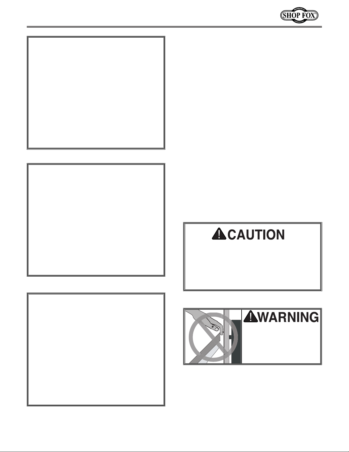
Keep fingers and clothing
away from the sanding
back stop. Failure to
comply may result in
serious personal injury.
Page 28
-25-
Disc Sanding
The disc is best used for sanding end grain and
convex curves.
1. Set the working table to the desired angle.
2. Always use the left half of the disc. (The
half that is rotating downward.)
3. Set the miter gauge at 90° to keep the work-
piece perpendicular to the sanding disc as
shown in Figure 35.
4. Varying angles can be sanded by adjusting
the miter gauge to the desired setting as
shown in Figure 36.
5. When the table is set at an angle, the gap
between the disc and the table becomes
greater (Figure 37); therefore, use extra
care to prevent small pieces and fingers
from becoming lodged in the gap.
Only use the left half of the sanding disc
when performing sanding operations. The
right half of the disc is rotating in an
upward direction and if used could cause
the workpiece to be propelled into the air.
Serious injury could occur.
Keep fingers and clothing
away from the sanding
disc. Failure to comply
may result in serious personal injury.
Figure 35. Sanding end grain.
Figure 37. Using table to sand angles.
Figure 36. Using miter gauge to sand angles.
Page 29
-26-
MAINTENANCE
Lubrication
Since all bearings are sealed and permanently
lubricated, simply leave them alone until they
need to be replaced. Do not lubricate them.
For other items on this machine, an occasional
application of light machine oil is all that is necessary. Before applying lubricant, wipe the
machine clean.
Your goal is to achieve adequate lubrication.
Too much lubrication will attract dirt and sawdust. Various parts of your machine could lose
their freedom of movement as a result.
Regular periodic maintenance on your Model
W1676 will ensure its optimum performance.
Make a habit of inspecting your sander each time
you use it. Check for the following conditions
and repair or replace when necessary.
1. Loose mounting bolts.
2. Worn switch.
3. Worn or damaged cords and plugs.
4. Damaged sanding belts or discs.
5. Any other condition that could hamper the
safe operation of this machine.
General
Table And Base
Tables can be kept rust-free with regular applications of products like Boeshield
®
T-9. For long
term storage you may want to consider products
like Kleen Bore's Rust Guardit™.
Wear safety glasses during the entire maintenance process. Failure to
comply may result in
serious personal injury.
Keep loose clothing
rolled up and out of the
way of machinery and
keep hair pulled back.
Disconnect power to the
machine when performing any maintenance,
assembly or adjustments. Failure to do this
may result in serious
personal injury.
!
Page 30
-27-
The following pages contain parts diagrams/lists
and a warranty card for your Shop Fox
®
Model
W1676.
If you need parts or help in assembling your
machine, or if you need operational information, we encourage you to call our Technical
Department. Our trained technical technicians
will be glad to help you.
If you have comments dealing specifically with
this manual, please write to us using the address
in the General Information. The specifications,
drawings, and photographs illustrated in this
manual represent the Model W1676 as supplied
when the manual was prepared. However, due
to Woodstock International, Inc.’s policy of continuous improvement, changes may be made at
any time with no obligation on the part of
Woodstock International, Inc. Whenever possible, though, we send manual updates to all owners of a particular tool or machine that have registered their purchase with our warranty card.
Should you receive one, add the new information to this manual and keep it for reference.
We have included some important safety measures that are essential to this machine’s operation. While most safety measures are generally
universal, we remind you that each workshop is
different and safety rules should be considered
as they apply to your specific situation.
We recommend you keep this manual for complete information regarding Woodstock
International, Inc.’s warranty and return policy.
Should a problem arise, we recommend that you
keep your proof of purchase with your manual.
If you need additional technical information
relating to this machine, or if you need general
assistance or replacement parts, please contact
the Service Department at 1-360-734-3482 or email: [email protected]
.
Additional information sources are necessary to
realize the full potential of this machine. Trade
journals, woodworking magazines, and your
local library are good places to start.
The Model W1676 is specifically designed for
sanding operations. DO NOT MODIFY AND/OR
USE THIS SANDER FOR ANY OTHER PURPOSE.
MODIFICATIONS OR IMPROPER USE OF THIS
TOOL WILL VOID THE WARRANTY. If you are
confused about any aspect of this machine, DO
NOT use it until all your questions have been
answered.
CLOSURE
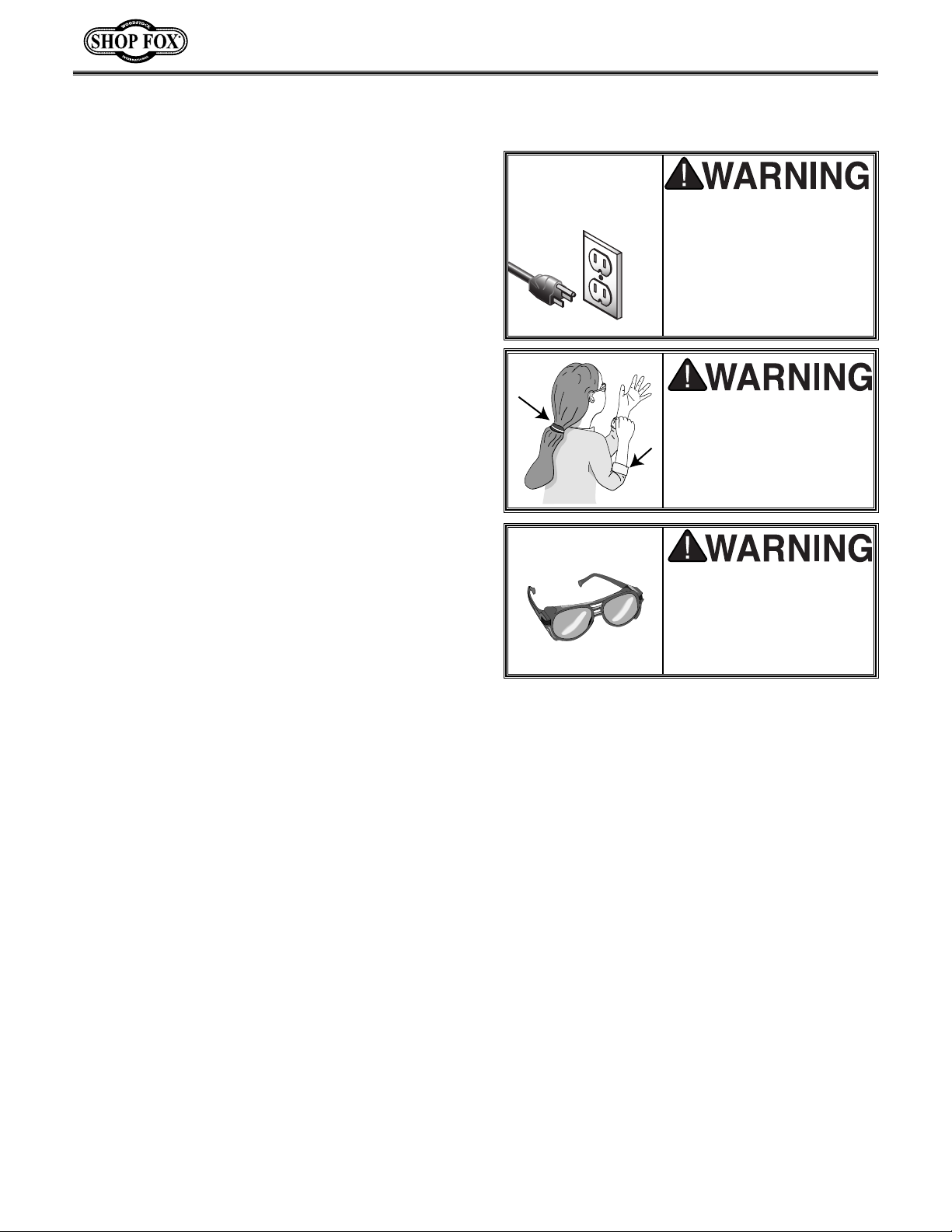
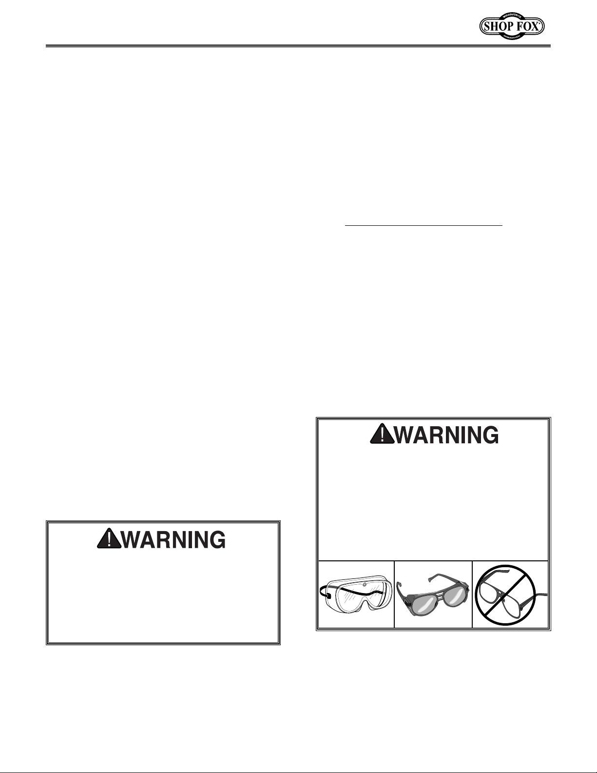
Operating this equipment creates the potential for flying debris to cause eye injury.
Always wear safety glasses or goggles when
operating equipment. Everyday glasses or
reading glasses only have impact resistant
lenses, they are not safety glasses. Be certain the safety glasses you wear meet the
appropriate standards of the American
National Standards Institute (ANSI).
As with all power tools, there is danger
associated with the Model W1676. Use the
tool with respect and caution to lessen the
possibility of mechanical damage or operator injury. If normal safety precautions are
overlooked or ignored, injury to the operator or others in the area is likely.
Page 31
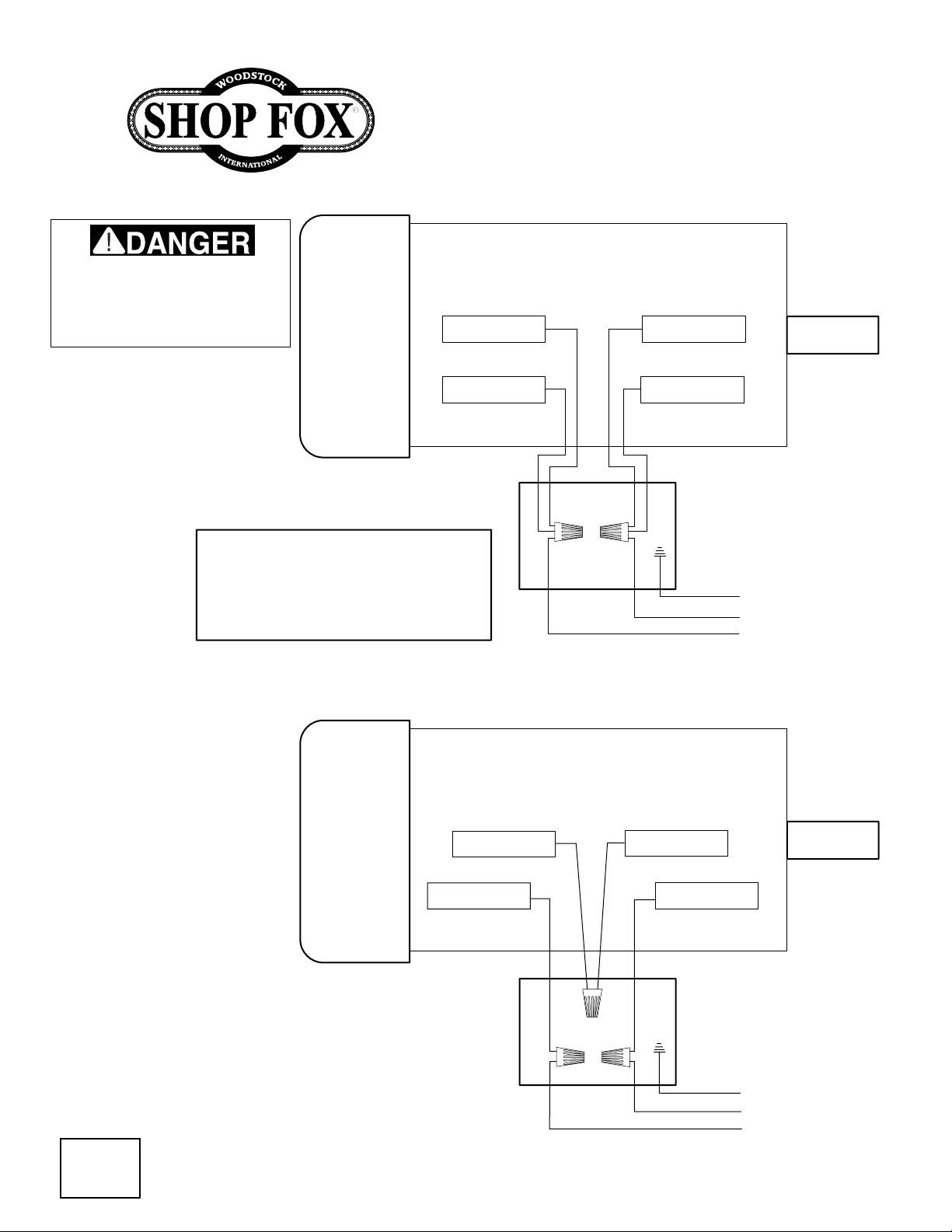
Disconnect power from machine
-28-
before performing any electrical
service. Failure to do this will
result in a shock hazard leading
to injury or death.
W1676 Combination Sander
110 VOLT
MOTOR WIRES
BLACK YELLOW
NOTE: THE WIRES FROM THE
POWER SUPPLY, BESIDES THE
GREEN GROUND WIRE, ARE
INTERCHANGABLE, THEREFORE
COLORS ARE NOT SPECIFIED.
WHITE
RED
GREEN (GROUND)
TO 110 VOLT
POWER SUPPLY
220VOLT
MOTOR WIRES
6A
RED
BLACK
YELLOW
WHITE
GREEN (GROUND)
TO 220 VOLT
POWER SUPPLY
©2001 Woodstock International
Page 32
90
13
32
70
40
93
120
18
41
43
97
80
37
41
97
51
36
57
10
46
119
118
56
52
96
30
97
12
13
32
19
32
77
42
35
34
21
22
97
32
42
10
44
23
45
69
51
27
33
27B
28A
20
69A
25
26
28B
69B
28C
27A
33
20A
29
24
97
14
13
27
32
25
28
12
26
10
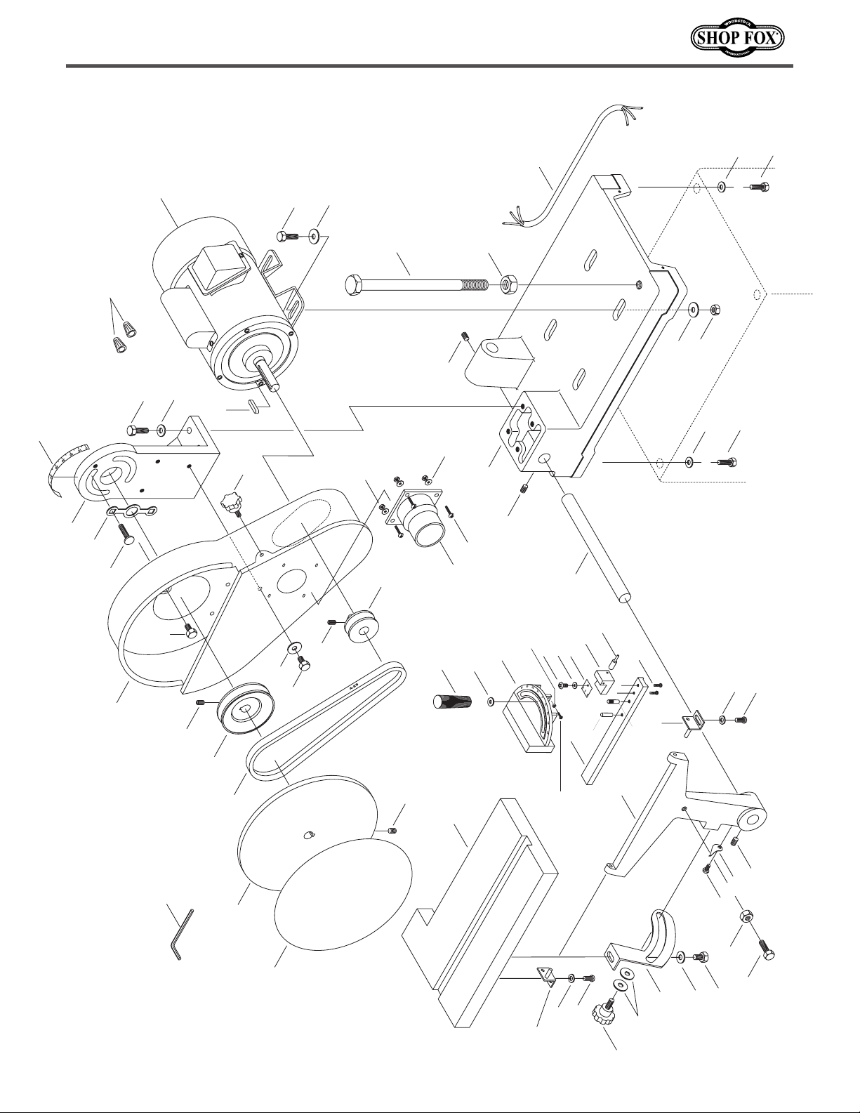
41
Page 33
2
3
64
114
5
107
91
25
115
81A
87A
101
88A
59
82A
105
85A
86A
1
2A
3A
98
99
105
94
102
62A
B
8
106
62A
B
89
83A
106
84A
3
2
89
92
100
96
11
96
12
95
103
9
13
41
4
6
15
7
Page 34
49
71
90A
27
53
46
51
53A
110
111
113
112
121
123
104
122
104A
41
110B
110B
110A
58
110C
12
13
Page 35

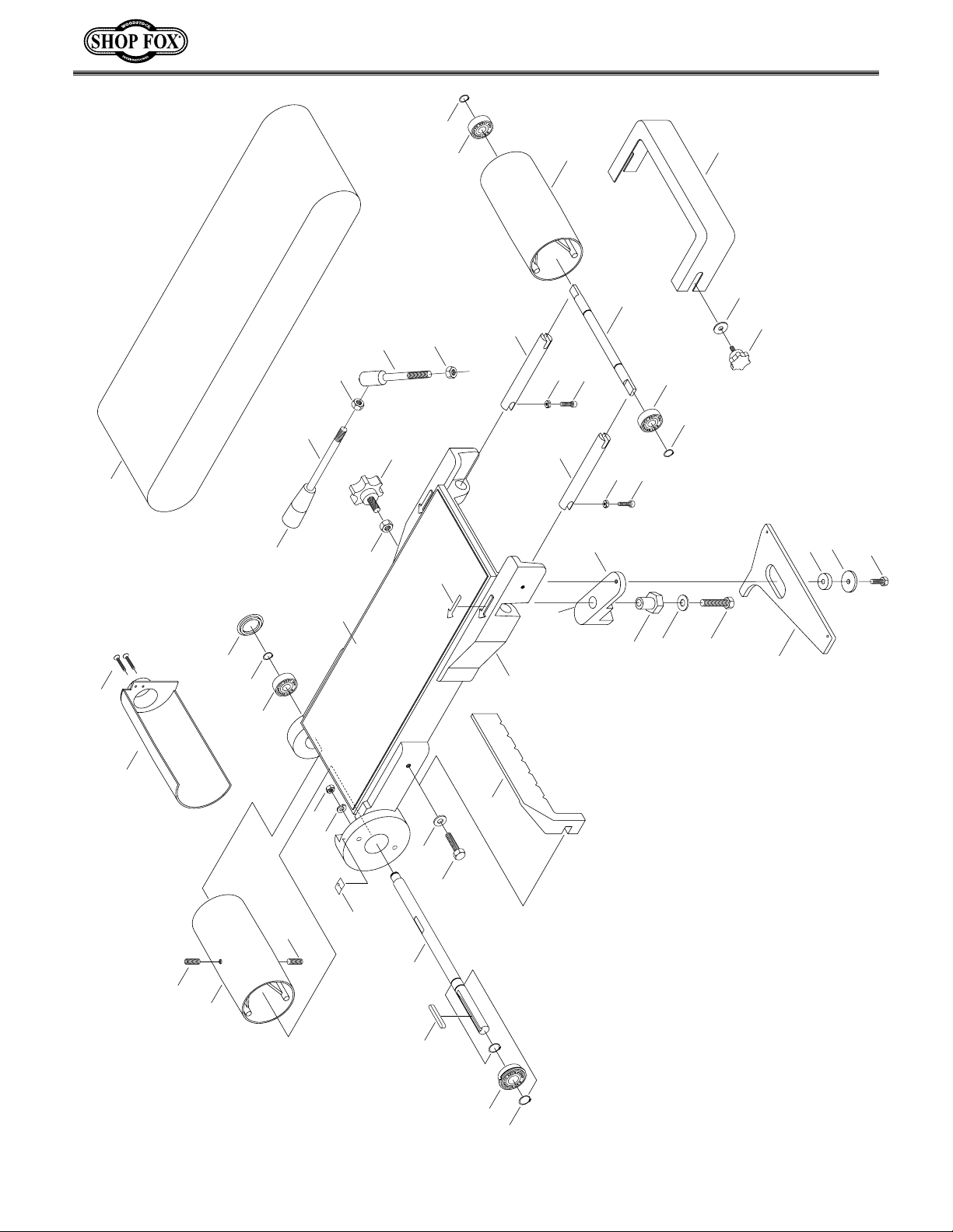
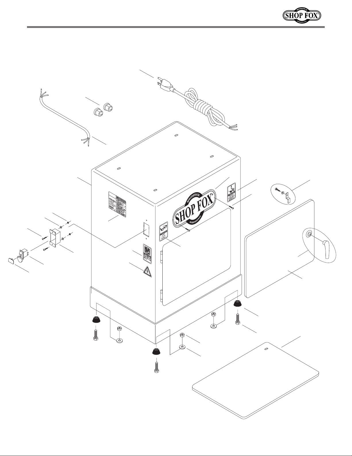
ref part # description
ref part # description
01 X1676001 DUST COVER
02 XPR03M SNAP RING 12MM
02A XPR05M SNAP RING 15MM
03 XP6201-2RS BALL BEARING 6201-2RS
03A XP6002-2RS BALL BEARING 6002-2RS
04 X1676004 DRIVE SHAFT
05 X1676005 SANDING BELT 6'' X 48''
06 XPK02M KEY 5 X 5X 40
07 X1676007 SNAP RING 16MM
08 X1676008 SANDING BELT FRAME
09 X1676009 BACK STOP
10 XPSS02 SETSCREW 5⁄16"-18 x 3⁄8"
11 X1676011 DRIVE ROLLER
12 X1676012 HEX NUT 5⁄16"-18
13 X1676013 5⁄16" FLAT WASHER
14 X1676014 KNOB
15 X1676015 BEARING 6003-2RS
16 X1676016 COMPLETE MITER GAUGE ASSY
18 X1676018 CARRIAGE BOLT 5⁄16"-18 x 11⁄4"
19 X1676019 PULLEY COVER
20 X1676020 MITER BAR
20A X1676020A STUD 1⁄4"
21 X1676021 CAST IRON DISC 10''
22 X1676022 SANDING DISC PAPER 10"
23 X1676023 TABLE
24 X1676024 TRUNNION
25 XPW06 FLAT WASHER 1⁄4"
26 XPS04 PHILLIPS® SCREW 1⁄4"-20 X 1⁄2"
27 X1676027 PHILLIPS® SCREW 10-24 X 1⁄4"
27A X1676027A PHILLIPS® SCREW 10-24 X 3⁄8"
27B X1676027B FLAT WASHER 3⁄16"
28 X1676028 TABLE POINTER
28A X1676028A MITER POINTER
28B X1676028B LOCK BRACKET
28C X1676028C LOCK PIN
29 X1676029 TABLE SUPPORT BRACKET
30 X1676030 SUPPORT BAR
32 XPB09 HEX BOLT 5⁄16"-18 x 1⁄2"
33 X1676033 TABLE MOUNT
34 X1676034 V-BELT 3L-240
35 X1676035 PULLEY
36 X1676036 MOTOR PULLEY
37 X1676037 KNOB
40 X1676040 BRACKET
41 XPB03 HEX BOLT 5⁄16"-18 x 1"
42 XPSS03 SETSCREW
43 X1676043 MOTOR
44 X1676044 LOCK KNOB
45 X1676045 PLASTIC WASHER 1⁄4"
46 X1676046 FLAT WASHER 3⁄16"
49 X1676049 STRAIN RELIEF FITTINGS
51 X1676051 HEX NUT 10-24
52 X1676052 BASE
53 X1676053 SWITCH LOCK
parts
53A X1676053A SWITCH
56 XPN04 HEX NUT 5⁄8''-11
5
⁄16"-18 x 1⁄4"
-32-
57 X1676057 SUPPORT 5⁄8''-11 x 9''
58 X1676058 RUBBER FOOT
59 X1676059 IDLER ROLLER SHAFT
62A X1676062B ROLLER ADJ BAR
64 X1676064 IDLER ROLLER
69 X1676069 MITER BODY
69A X1676069A PHILLIPS® SCREW 10-24 x 3⁄4"
69B X1676069B PIN 1⁄4"
70 X1676070 SCALE
71 X1676071 POWER CORD
77 XPAW04M ALLEN® WRENCH 4MM
80 XPK23M KEY 5 X 5 X 25
81A X1676081A ROCKER ARM
82A X1676082A LEVER, SHORT
83A X1676083A ROCKER ARM
84A X1676084A ECCENTRIC
85A X1676085A LEVER, LONG
86A X1676086A KNOB, 3⁄8"-16
87A X1676087A SPACER
88A XPB21 HEX BOLT 3⁄8"-16 x 3⁄4"
89 XPSB31 CAP SCREW 10-24 x 5⁄8"
90 X1676090 MOTOR CORD (1)
90A X1676090A MOTOR CORD (2)
91 XPB16 HEX BOLT 3⁄8"-16 x 11⁄2"
92 XPW02 FLAT WASHER 3⁄8"
93 X1676093 WASHER PLATE
94 X1676094 KNOB
95 XPLW01 LOCK WASHER 5⁄16"
96 XPSS18 SETSCREW 5⁄16"-18 x 3⁄4"
97 XPW07 FLAT WASHER 5⁄16"
98 XPN11 HEX NUT 3⁄8''-24
99 X1676099 GRAPHITE PAD
100 X1676100 DUST PORT ABS
101 X1676101 FLAT WASHER 3⁄8"
102 X1676102 DIRECTION SCALE
103 X1676103 POINTER
104 X1676104 LOGO
104A
X1676104A LOGO SCREW
105 XPN08 HEX NUT
3
⁄8"-16
106 X1676106 HEX NUT 10-24
107 X1676107 PHILLIPS® SCREW 3⁄16"-24 X 3⁄8"
110 X1676110 CABINET
110A
X1676110A CABINET DOOR
110B
X1676110B DOOR LATCH SYSTEM
110C X1676110C SHELF
111 X1676111 SWITCH HOUSING
112 X1676112 READ MANUAL WARNING
113 X1676113 MACHINE ID/WARNING
114 X1676114 IDLER ROLLER GUARD
115 X1676115 LOCK KNOB
118 X1676118 PHILLIPS® SCREW 3⁄16"-24 X 3⁄8"
119 X1676119 DUST PORT
120 X1676120 WIRE CONNECTOR 1⁄2"
121 X1676121 ELECTRICITY WARNING
122 X1676122 UNPLUG WARNING
123 X1676123 SAFETY GLASSES WARNING
Page 36

-33-
Notes
Page 37

-34-
Notes
Page 38

CUT ALONG DOTTED LINE
10. What stationary woodworking tools do you own? Check all that apply.
___Air Compressor ___Panel Saw
___Band Saw ___Planer
___Drill Press ___Power Feeder
___Drum Sander ___Radial Arm Saw
___Dust Collector ___Shaper
___Horizontal Boring Machine ___Spindle Sander
___Jointer ___Table Saw
___Lathe ___Vacuum Veneer Press
___Mortiser ___Wide Belt Sander
___Other__________________________________________________
11. Which benchtop tools do you own? Check all that apply.
___1" x 42" Belt Sander ___6" - 8" Grinder
___5" - 8" Drill Press ___Mini Lathe
___8" Table Saw ___10" - 12" Thickness Planer
___8" - 10" Bandsaw ___Scroll Saw
___Disc/Belt Sander ___Spindle/Belt Sander
___Mini Jointer
___Other__________________________________________________
12. Which portable/hand held power tools do you own? Check all that apply.
___Belt Sander ___Orbital Sander
___Biscuit Joiner ___Palm Sander
___Circular Saw ___Portable Planer
___Detail Sander ___Saber Saw
___Drill/Driver ___Reciprocating Saw
___Miter Saw ___Router
___Other__________________________________________________
13. What machines/supplies would you like to see?
_________________________________________________________
_________________________________________________________
_________________________________________________________
_________________________________________________________
14. What new accessories would you like Woodstock International to carry?
_________________________________________________________
_________________________________________________________
15. Do you think your purchase represents good value?
___Yes ___No
16. Would you recommend Shop Fox
®
products to a friend?
___Yes ___No
17. Comments:________________________________________________
__________________________________________________________
__________________________________________________________
__________________________________________________________
__________________________________________________________
__________________________________________________________
__________________________________________________________
1. Where did you purchase your Shop Fox
®
machine?
_________________________________________________________
2. How did you first learn about us?
___Advertisement ___Friend
___Mail order Catalog ___Local Store
___World Wide Web Site
___Other__________________________________________________
3. Which of the following magazines do you subscribe to.
___American Woodworker ___Today’s Homeowner
___Cabinetmaker ___Wood
___Family Handyman ___Wooden Boat
___Fine Homebuilding ___Woodshop News
___Fine Woodworking ___Woodsmith
___Home Handyman ___Woodwork
___Journal of Light Construction ___Woodworker
___Old House Journal ___Woodworker’s Journal
___Popular Mechanics ___Workbench
___Popular Science ___American How-To
___Popular Woodworking
___Other__________________________________________________
4. Which of the following woodworking/remodeling shows do you watch?
___Backyard America ___The New Yankee Workshop
___Home Time ___This Old House
___The American Woodworker ___Woodwright’s Shop
___Other__________________________________________________
5. What is your annual household income?
___$20,000-$29,999 ___$60,000-$69,999
___$30,000-$39,999 ___$70,000-$79,999
___$40,000-$49,999 ___$80,000-$89,999
___$50,000-$59,999 ___$90,000 +
6. What is your age group?
___20-29 ___50-59
___30-39 ___60-69
___40-49 ___70 +
7. How long have you been a woodworker?
___0 - 2 Years ___8 - 20 Years
___2 - 8 Years ___20+ Years
8. How would you rank your woodworking skills?
___Simple ___Advanced
___Intermediate ___Master Craftsman
9. How many Shop Fox®machines do you own? _____________
Name __________________________________________________________________________________________
Street __________________________________________________________________________________________
City ____________________________________________________________________State________Zip_________
Phone Number_______________________E-Mail_________________________________FAX___________________
MODEL #W1676 Combination Sander
The following information is given on a voluntary basis and is strictly confidential.
WARRANTY CARD
Page 39

TAPE ALONG EDGES--PLEASE DO NOT STAPLE
FOLD ALONG DOTTED LINE
FOLD ALONG DOTTED LINE
WOODSTOCK INTERNATIONAL, INC.
P.O. BOX 2309
BELLINGHAM, WA 98227-2309
Place
Stamp
Here
 Loading...