

Page 1
MODEL M1024
TAPER ATTACHMENT
FOR USE WITH MODEL M102 0
INSTRUCTION MANUAL
Phone: 1-360-734-3482 • On-Line Technical Support: tech-support@shopfox.biz
COPYRIGHT © JANUARY, 2005 BY WOODSTOCK INTERNATIONAL, INC.
WARNI NG: NO PO RTION OF THI S MANUA L MAY B E REPRO DUCED IN ANY S HAPE OR F ORM WITHOU T
#6726 BL
THE WRI TTEN AP PROVAL OF WO ODSTO CK INTERNATIONA L, INC.
Print ed in Tai wan
Page 2

M1024 Taper Attachment
-2-
Page 3
M1024 Taper Attachment
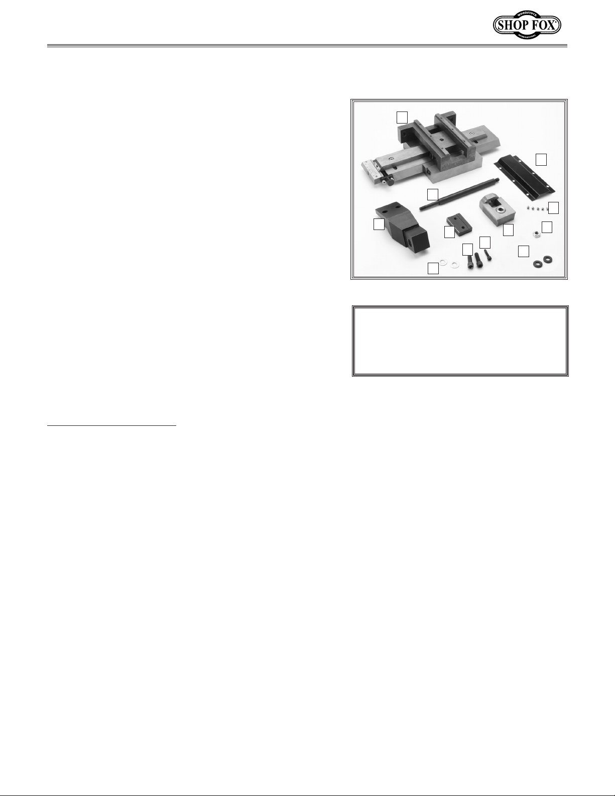
INVENTORY
The following is a description of the main components
shipped with the
Attachment. Lay the components out to inventory them.
Box Contents (Figure
QTY
A. Taper Attachment Body ..................................1
B. Clamping Bracket ..........................................1
C. Clamping Jaw ..............................................1
D. Support Rod ................................................1
E. Top Cover Plate ...........................................1
F. End Block ...................................................1
G. Cap Screws M10-1.5 x 35 .................................2
H. Cap Screw M6 x 25 ........................................1
I. Hex Nut M10-1.5 ...........................................2
J. Flat Washers 10mm .......................................2
K. Spacers 12mm ..............................................2
L. Phillips Head Screws M5-1 x 6 ...........................6
If any parts appear to be missing, examine the packag
ing carefully to be sure those parts are not among the
packing materials. If any parts are missing, find the
part number in the back of this manual and contact
Woodstock International, Inc. at 360-734-3482 or at
tech-support@shopfox.biz
SHOP FOX
1)
®
Model M1024 Taper
-
A
E
D
L
B
Figure 1. Main contents.
C
G
J
F
H
I
K
NOTICE
When ordering replacement parts, refer
to the parts list and diagram in the back
of the manual.
-3-
Page 4
INSTALLATION
The Model M1024 Taper Attachment mounts quickly to
the back of the carriage and bed way of the Model M1020
Gear Head Lathe. Accurate tapers up to 6" can be pro
duced without repositioning the attachment. The Model
M1024 features a scale for reading degrees.
adjusting screw with fine threads achieves precise control
when setting tapers. Another feature is the ability to use
it without disengaging the cross slide nut. This will allow
it to be functional at any time by simply tightening the
deadman.
The Model M1024 comes carefully packaged and coated
with grease for rust protection. You will need to clean
all pieces thoroughly prior to installation and use. Use a
solvent cleaner or citrus-based degreaser. For optimum
performance from your machine, make sure you clean
all moving parts or sliding contact surfaces that are
coated. Avoid chlorine-based solvents and gasoline as
they may damage painted surfaces should they come in
contact. Always follow the manufacturer’s instructions
when using any type of cleaning product.
An angle
-
M1024 Taper Attachment
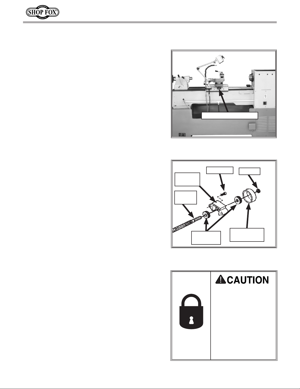
Cross Slide Lead Screw
Figure 2. Back of lathe with splash guard
removed.
Cap Screw
Bearing
Housing
Hex Nut
Installing the Taper
Attachment
To install the taper attachment, do these steps:
1. Disconnect the lathe from its power source!
2. Remove the splash guard from the back of the lathe
(Figure 2). If the lathe must be moved to allow
access to the splash guard, consult the lathe manual
for safe moving information.
: If you move the lathe, be sure to re-level it
Note
after returning the lathe to its final location.
3. Remove the hex nut that holds the bearings in place
at the end of the cross slide lead screw (Figures 2 &
3).
4. Remove the bearing dust cover and thrust bearing
from the end of the lead screw.
Lead
Screw
Thrust
Bearings
Figure 3. Cross lead screw components on
lathe.
MAKE your shop “child
safe.” Ensure that your
workplace is inacces
sible to youngsters by
closing and locking all
entrances when you
are away. NEVER allow
untrained visitors in
your shop when assembling, adjusting or
operating equipment.
Bearing Dust
Cover
-
-4-
Page 5

M1024 Taper Attachment
5. Remove the two cap screws securing the bearing
housing. Leave the remaining thrust bearing on the
lead screw (
6. Remove the six Phillips head screws from the top
cover plate of the taper attachment body. Set the
screws and cover aside for later use.
7. Remove the cap screw and end block from the taper
attachment body (
8. Slide the end block and the thrust bearing over the
lead screw.
9. Thread the end nut onto the end of the lead screw
(Figure 6) and tighten the nut while holding the
cross slide handwheel
To check, turn the end block. Only a small amo
of resistance should be felt. Adjust the nut as need
ed.
Figure 4).
Figure 5).
. Do not over-tighten the nut.
unt
-
Bearing
Housing
Bearing
Dust Cover
Hex Nut
Thrust Bearing
Figure 4. Lead screw component
identification.
Lead Screw
Cap
Screws
Thrust
Bearing
Pieces
End block
Figure 5. Removing end block from main
body.
Figure 6. Installing end block onto lead
screw.
-5-
Page 6

Mounting Taper
Attachment Body
The taper attachment is heavy and could cause serious injury if it drops on you. To minimize this possi
bility, have an assistant hold the main body while it
is being attached to the lathe
To mount the taper attachment, do these steps:
1. Remove any paint or debris from the two threaded-
holes on the rear of the lathe carriage. Debris could
cause the taper attachment bolts to not screw in
completely.
.
M1024 Taper Attachment
-
2. With the help of an assistant, align the the two holes
on the taper attachment body with the thread holes
on the lathe carriage. Use two M10-1.5 x 35 cap
screws to loosely fasten the main body to the lathe.
A long-handled, ball end 8 mm
best for this step (
3. Tighten the two cap screws adjacent to the lathe on
the underside of the taper attachment body (
8).
4. Turn the cross slide handwheel to align the hole
in the end block with the hole in the taper slide
(Figure 9).
Note: The dovetail ways of the cross slide must clear
the top of the taper attachment and line up with the
dovetails on the taper attachment. The mounting
holes in the taper attachment are oversized to allow
for minor height adjustments.
5. Adjust the taper attachment for clearance and check
that the cross slide moves in and out, along its full
range of motion, without increased resistance. When
the cross slide moves unobstructed and smoothly,
tighten the mounting screws.
Figure 7).
hex wrench works
Figure
Figure 7. Mounting main body onto lathe
while tightening cap screws.
Figure 8. Tightening cap screws under
main body.
Cross Slide
Mounting
Screws
Main
Slide
6. Reassemble the top cover plate, using the six
Phillips© head screws.
-6-
Taper
Bar
Figure 9. Tightening cap screw on end
block.
Taper
Slide
Page 7

M1024 Taper Attachment
Deadman Installation
The deadman is composed of a solid cast clamping bracket and a loose clamping jaw. The bracket has two holes
for clamping screws that attach the clamping jaw (Figure
10).
Clamping
Screw
To attach the deadman, do these steps:
1. Place the clamping bracket over the lathe bed way
and slide the clamping jaw underneath the bracket.
2. Place clamping screws into the two holes on the
clamping bracket and tighten them.
3. Adjust the clamping screws until the clamping jaw
and bottom of the bed way are parallel. If these surfaces are not parallel, loosen the clamping screws
and adjust them as needed.
4. Fasten the short threaded end of the support rod
into the hole on the left side of the taper attachment body and turn the rod counterclockwise until it
fits tightly (
5. Place a washer over the longer threaded end of the
support rod.
6. Loosen the clamping screws enough to slide the support rod through the hole in the clamping bracket.
Figure 11).
Clamping
Bracket
Bed
Way
Clamping Jaw
Figure 10. Deadman components.
Deadman
Support Rod
7. Slide a second washer over the threads, and fasten a
M10-1.5 nut to the end of the rod.
8. Adjust the position of the clamping bracket until
the support rod is parallel with the lathe bed and
tighten the clamping screws on the clamping bracket
(Figure 12).
Note: Position the deadman as close to the main
body as possible for the best stability
9. Re-attach the splash guard to the lathe and reposition the lathe as needed.
.
Figure 11. Installing support rod onto
taper attachment.
Figure 12. Deadman installed onto taper
attachment.
-7-
Page 8

OPERATIONS
Angle Adjustments
The taper angle is adjusted by loosening the two cap
screws at the ends of the taper bar on the taper attach
ment. The angle adjusting knob allows for fine control
of the angle (Figure 13). A scale on the left side of the
taper (labeled in degrees) allows you to get close to the
desired taper, but finer adjustments should be made
with an indicator and test bar. Once the desired setting
is reached, tighten the two cap screws. Double check the
setting to ensure accuracy.
-
Scale
M1024 Taper Attachment
Cap Screw
on Taper
Bar
Angle
Adjusting
Knob
Deadman Adjustments
To use the taper attachment, tighten the clamping screws
on the deadman to secure it to the lathe bed. When
not in use, loosen the clamping screws. Removal of the
deadman or the taper attachment is not necessary when
changing from taper turning to straight turning.
Figure 13. Angle adjustment scale.
Always wear safety glasses when operating the lathe. Failure to comply may
result in serious personal injury.
-8-
DO NOT investigate problems or adjust
the lathe while it is running. Wait until
the machine is turned off, unplugged
and all working parts have come to a
complete stop before proceeding!
Page 9

M1024 Taper Attachment
Top Gib Adjustments
The top gib, shown in Figure 14, is mounted to a taper
that moves along the taper bar on the taper attach-
slide
ment. The slide maintains the motion of the cross slide
to produce the taper. If the gib is too loose, the angle
can be affected and the finish will suffer. If the gib is too
tight, the slide will not move freely.
To adjust the top gib, do these steps:
Top
Gib
Screw
Top
Gib
1. Adjust the taper bar angle to zero.
2. To tighten the gib, loosen the gib screw on the left
side of the taper slide (as viewed from the front of
the lathe) and tighten the right screw (see
14). To loosen the gib, loosen the right screw and
tighten the left screw.
3. The gib is properly adjusted when the taper slide
can be moved by hand with moderate force.
Figure
Bottom Gib Adjustments
The bottom gib, shown in Figure
back inside edge of the main body casting. If the gib is
too loose, finish problems will occur. If the gib is too
tight, the main slide will not move smoothly.
To adjust the bottom gib, do these steps:
1. To tighten the gib, loosen the gib screw on the left
(as viewed from the front of the lathe) and tighten
the right screw. To loosen the gib, loosen the right
screw (Figure 14
) and tighten the left screw.
14, is mounted on the
Bottom
Gib
Screw
Figure 14. Gibs and gib screws.
Bottom
Gib
2. Double-check the main slide to ensure that it moves
smoothly. Re-adjust if necessary.
3. Re-attach the support rod to the taper attachment
body.
-9-
Page 10

M1024 Taper Attachment
PARTS
-10-
Page 11

M1024 Taper Attachment
REF PART # DESCRIPTION REF PART # DESCRIPTION
1 XM1024001 CLAMPING JAW 21 XM1024021 SUPPORT SPACER
2 XM1024002 CLAMPING BRACKET 22 XM1024022 PINNED KNOB
3 XPSB40M CAP SCREW M8-1.25 X 35 23 XPRP61M ROLL PIN 3 X 12
4 XPN02M HEX NUT M10-1.5 24 XM1024024 TAPER SLIDE GIB
5 XM1024005 SPACER 12MM 25 XM1024025 TAPER SLIDE
6 XM1024006 SUPPORT ROD 26 XM1024026 GIB SCREW M8-1 X 20
7 XM1024007 SCALE PLATE 27 XM1024027 GIB
8 XPS49M PHLP HD SCR M3-.5 X 5 28 XPSB12M CAP SCREW M8-1.25 X 40
9 XM1024009 INDICATOR PLATE 29 XM1024029 BLOCK
10 XPS49M PHLP HD SCR M3-.5 X 5 30 XPSS26M SET SCREW M5-.8 X 6
11 XM1024011 TAPER BAR 31 XM1024031 COVER
12 XPN03M HEX NUT M8-1.25 32 XPS19M PHLP HD SCR M5-.8 X 6
13 XPSB31M CAP SCREW M8-1.25 X 25 33 XPSB84M CAP SCREW M10-1.5 X 35
14 XPSB58M CAP SCREW M8-1.25 X 12 34 XPW04M FLAT WASHER 10MM
15 XM1024015 PIVOT BLOCK 35 XM1024035 TAPER ATTACHMENT BRACKET
16 XM1024016 MAIN SLIDE 36 XPSB06M CAP SCREW M6-1 X 25
17 XM1024017 BLOCK NUT 37 XM1024037 SHOULDER BUSHING
18 XM1024018 TAPER ANGLE LEADSCREW 38 XM1024038 SLIDE BLOCK
19 XM1024019 BLOCK 39 XM1024039 END BLOCK
20 XPSB01M CAP SCREW M6-1 X 16 40 XPSB01M CAP SCREW M6-1 X 16
Parts List
-11-
Page 12

 Loading...