

Page 1
Model D3348
Extension Block Kit
Instruction Sheet
Phone #: (360) 734-3482 • Online Tech Support: [email protected] • Web: www.shopfox.biz
INTRODUCTION
This Extension Block Kit increases the maximum cutting
height of the Model W1706 14" bandsaw from 6" to 12".
INVENTORY
Description Qty
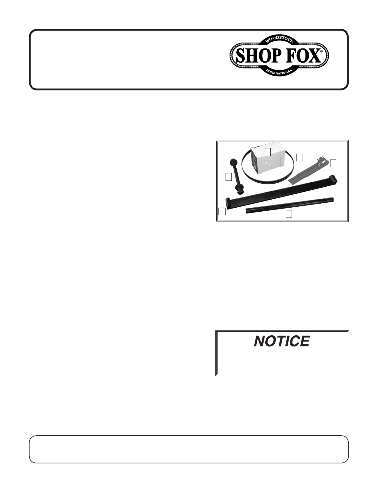
A. Extension Block ............................................1
B. Saw Blade 105" .............................................1
C. Extended Saw Blade Guard ..............................1
D. Extended Guide Post ......................................1
E. Hardware
—Hex Bolt
—Hex Nut
5
—
—Cord Clamp ACC-3 (not shown)........................1
—Phillips Hd 10-24 x
F. Extended Blade Guard Assembly ........................1
⁄8" Flat Washer ..........................................2
5
⁄8"-11 x 8-1⁄2" ................................1
5
⁄8"-11 ...........................................1
1
⁄2" (not shown) ..................1
E
C
Figure 1. Extension Block Kit.
A
B
D
F
Items Needed
Description Qty
Adjustable Wrenches .......................................... 2
Phillips Screwdriver #2 .........................................1
Hex Wrench 5mm and 3mm ............................ 1 Each
Another Person for Assistance ................................1
Cleanup
The unpainted surfaces of the extension block are
coated with a heavy-duty rust preventative that prevents
corrosion during shipment and storage.
Complete removal of the rust preventative is necessary
for the extension block and upper arm to fit properly and
be accurately positioned.
COPYRIGHT © OCTOBER, 2004 BY WOODSTOCK INTERNATIONAL, INC. REVISED JULY, 2013 (DM)
WARNING: NO PORTION OF THIS MANUAL MAY BE REPRODUCED IN ANY SHAPE OR FORM WITHOUT
THE WRITTEN APPROVAL OF WOODSTOCK INTERNATIONAL, INC.
Avoid chlorine-based solvents, such as
acetone or brake parts cleaner, that
may damage painted surfaces.
Printed in Taiwan#6714BL
Page 2
Before cleaning, gather the following:
• Disposable Rags
• Cleaner/degreaser (WD•40 works well)
• Safety glasses & disposable gloves
• Plastic paint scraper (optional)
Basic steps for removing rust preventative:
D3348 Extension Block Instructions
1. Put on safety glasses.
2. Apply a liberal amount of cleaner/degreaser on the
rust preventative, then let it soak for 5–10 minutes.
3. Wipe off the surfaces. If your cleaner/degreaser is
effective, the rust preventative will wipe off easily.
If you have a plastic paint scraper, scrape off as
much as you can first, then wipe off the rest with
the rag.
4. Repeat Steps 2–3 as necessary until clean, then
coat all unpainted surfaces with a quality metal
protectant to prevent rust.
Installation
1. DISCONNECT BANDSAW FROM POWER!
2. Remove the blade per the directions in the Model
W1706 Owner's Manual.
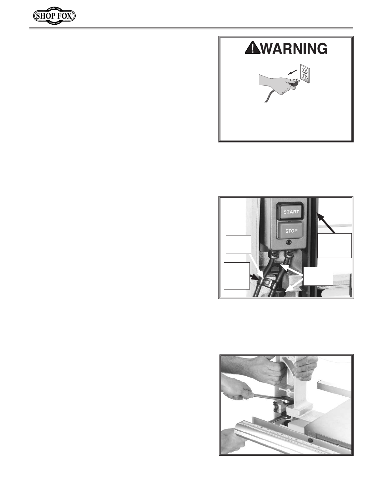
3. Remove the left-side blade guard (Figure 2). It is
held in place with one screw at the top and one at
the bottom.
4. Taking care not to disconnect any wiring, remove
the power switch and the double cord clamp (see
Figure 2). Let the switch hang to the side for now.
Disconnect power to the machine
when performing any maintenance or
assembly. Failure to do this may result
in serious personal injury.
Phillips
Screw
Double
Cord
Clamp
Figure 2. Power switch and left side blade
guard.
Left-side
Blade
Guard
Hex Nut
& Bolt
Note: The switch is fastened in place with one
screw above the box and one below it. Avoid
removing the two screws on the face of the switch
box, as this will open the switch box cover, exposing
the wiring inside.
5. Have an assistant support the upper arm assembly,
then loosen the hex nut and bolt, as shown in
Figure 3, and slide the bolt out.
IMPORTANT: Make sure all mating surfaces of the
riser block are clean before proceeding.
-2-
Figure 3. Loosening hex nut and bolt.
Page 3
D3348 Extension Block Instructions
Arrow on
Riser Block
Points Up and
Faces Behind
Bandsaw
Alignment Pins
Must Fit Completely
into Holes
Hex Bolt
5
⁄8" x 81⁄2"
Flat Washer
5
⁄8"
Flat Washer
5
⁄8"
Hex Nut
5
⁄8"
6. Remove the upper arm and set it aside.
Note: The upper arm is pinned to the base. If
removal is difficult, carefully rock the upper arm
loose.
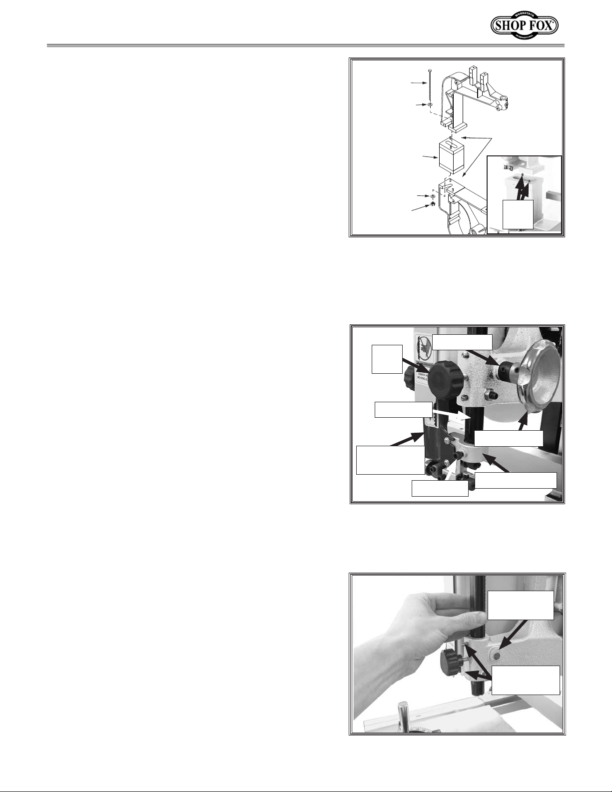
7. Place the extension block onto the base pins.
8. Have an assistant place the upper arm onto the
extension block pins (see Figure 4), and hold the
upper arm in place.
Note: Make sure the arrow on the riser block points
up and faces behind the machine. Also, make sure
the alignment pins fit completely into the holes
during installation.
5
9. Place a
⁄8" washer over the 5⁄8"-11 x 81⁄2" hex bolt
included with the extension kit, and slide the bolt
down through the extension block.
Base
Pins
Figure 4. Installing riser block.
5
10. Attach the
⁄8" washer and 5⁄8"-11 hex nut to the hex
bolt, and tighten until secure.
11. Install the extended left-side blade guard using the
screws removed in Step 3.
12. Raise the upper guide assembly all the way up, then
tighten the lock knob (see Figure 5).
13. Loosen the cap screw shown in Figure 5, disconnect
the guide assembly from the guide post, then
remove the guide assembly and the upper blade
guard.
14. Remove the guide post control knob and lock collar
from the pinion gear shaft (Figure 5).
15. Push the pinion gear shaft inward to disengage the
gear from the rack (see Figure 6).
16. Unthread the two ball plunger set screws (see Figure
6) away from the guide post. (It is not necessary to
remove them.)
17. Hold the guide post with one hand, then loosen the
lock knob with the other hand and slide the guide
post up and out of its housing.
Lock Collar
Lock
Knob
Guide Post
Control Knob
Upper Blade
Guard
Guide Assembly
Cap Screw
Figure 5. Upper blade guard and
components.
Pinion Gear
Disengaged
Ball Plunger
Set Screws
-3-
Figure 6. Pinion gear shaft pushed in.
Page 4
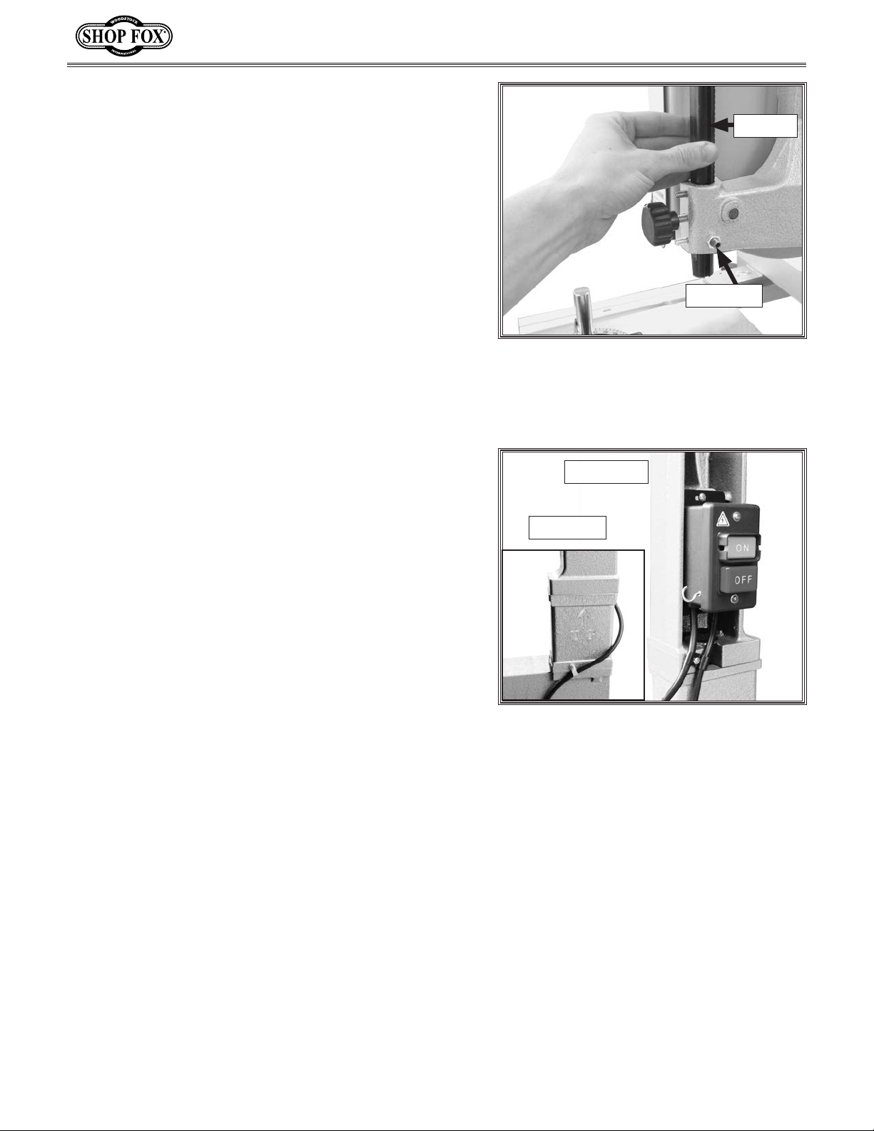
18. Insert the extended guide post into the housing,
as shown in Figure 7, making sure the keyway is
aligned with the set screw.
19. Slide the pinion gear away from the saw, and ensure
the gear teeth engage the guide post rack.
20. Thread the ball plunger set screws back into place—
but avoid over-tightening them. At the proper
setting, the guide post should move up and down by
hand, but remain stationary when the lock knob is
released.
21. Replace the lock collar and guide post control knob.
22. Attach the guide assembly and the extended blade
guard to the guide post.
1
23. Attach the cord clamp using (1) 10-24 x
⁄2" Phillips
head screw (see Figure 8), and replace the power
switch assembly and double cord clamp removed in
Step 4.
D3348 Extension Block Instructions
Keyway
Set Screw
Figure 7. Installing extended guide post.
Front View
24. Install the 105" bandsaw blade. Without starting
the saw, tension the blade approximately where it
should be for a regular cutting operation.
— If you have difficulty setting the tension on
the 105" blade, the tensioning mechanism on
the bandsaw may need to be re-adjusted to
accommodate the new blade length. Follow the
Blade Tensioner instructions in the W1706 Owner's
Manual.
25. Align the bandsaw wheels so they are coplaner. Refer
to Wheel Alignment procedure in the W1706 Owner's
Manual.
Congratulations! The riser block installation
procedure is now complete.
Rear View
Figure 8. Extension block installed.
-4-
Page 5
D3348 Extension Block Instructions
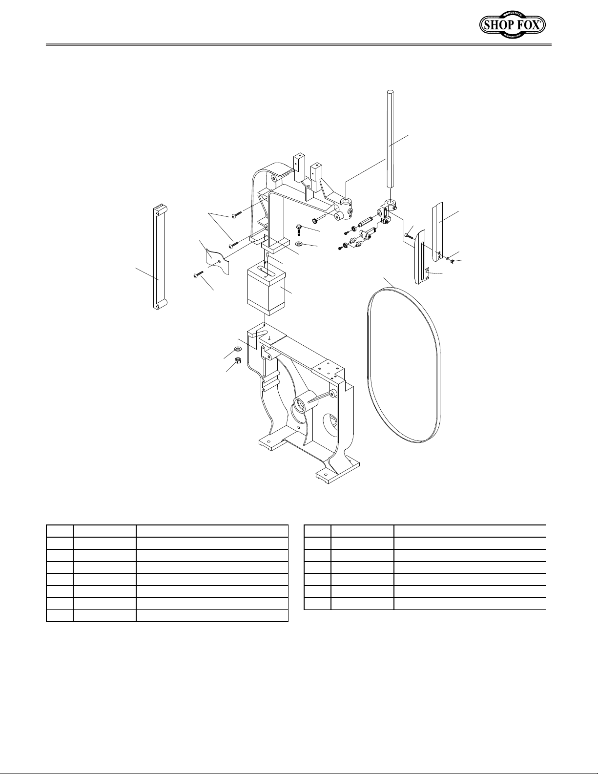
D3348 Parts Diagram
84A
65A
125A
124A
125A
3A
4A
5
152
3A
2A
60A
90B
162A
164
165
90A
REF PART # DESCRIPTION REF PART # DESCRIPTION
2A XD3348002A HEX BOLT 5/8-11 X 8-1/2 90B XD3348090B BLADE GUARD
3A XPW14 FLAT WASHER 5/8 152 XD3348152 EXTENSION BLOCK
4A XPN04 HEX NUT 5/8-11 162A XPCB02 CARRIAGE BOLT 5/16-18 X 1/2
5 XD3348005 PIN 6 X 15 164 XPW07 FLAT WASHER 5/16
60A XD3348060A SAW BLADE 6 TPI X 105 X 3/8 165 XPWN03 WING NUT 5/16-18
65A XD3348065A SAW BLADE GUARD 124A XD3348124A CORD CLAMP
84A XD3348084A GUIDE POST (LONG) 125A XPS01 PHLP HD SCR 10-24 X 1/2
90A XD3348090A BLADE GUARD (LONG)
-5-
 Loading...