

Page 1
Model D1700/D1701
Moulding Head
Instruction Sheet
Phone #: (360) 734-3482 • Online Tech Support: tech-support@shopfox.biz • Web: www.shopfox.biz
To reduce risk of serious personal injury when using
moulding head:
• Always wear ANSI-approved eye and hearing
protection when using moulding head.
• Never use on
• Never operate with only one knife installed.
• Always ensure BOTH knives are firmly secured in
place BEFORE starting shaper.
• Never feed lumber with rotation of moulding
head.
• Follow safety guidelines of shaper manufacturer.
1
⁄2" spindle.
Introduction
The D1700/D1701 2-Knife Moulding Head (see Figure 1) is
designed to be used on a vertical spindle shaper. It is made
of the highest quality aircraft aluminum and machined to
exact tolerances. The moulding head accepts matched
pairs of interchangeable, corrugated-backed high-speed
knives (not included). The moulding head will use either
60˚ or 90˚–cut corrugations that are spaced
The knives lock into position by wedge-type gibs for maximum safety.
1
⁄16" apart.
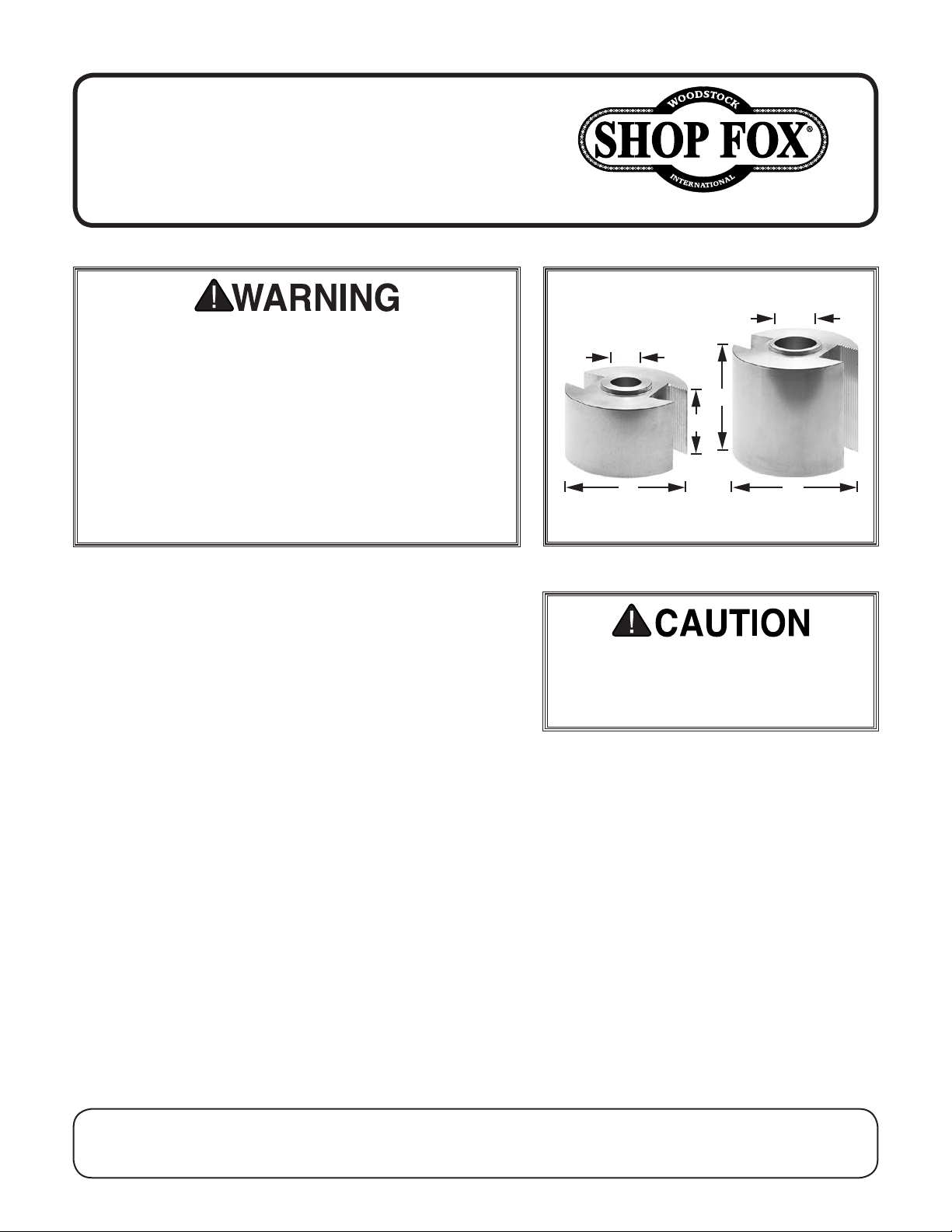
1"
¾"
3"
2"
D1700
3"
Figure 1. Moulding head dimensions.
Moulding knives have sharp edges. Use
care while removing them from package.
Remove oily film to help ensure knives
securely mount in moulding head.
D1701
3"
DO NOT use this moulding head on any machine other than
one equipped with a
spindle for the D1701. The shaper should have at least a
1
⁄2 HP motor. We also recommend operating a power
1
feeder when using the moulding head, as it helps feed the
workpiece steadily and consistently for best cutting
results, while at the same time helping you keep your
hands a safe distance away from the cutter.
Important: These instructions and drawings are intended
for explanation and clarification purposes only as they
pertain to the moulding head. You must apply all safety
measures as they relate to shaping operations and your
specific equipment. Review and apply all safety measures
before you use this moulding head.
WARNING: NO PORTION OF THIS MANUAL MAY BE REPRODUCED IN ANY SHAPE OR FORM WITHOUT
3
⁄4" spindle for the D1700, or 1"
COPYRIGHT © SEPTEMBER, 2015 BY WOODSTOCK INTERNATIONAL, INC.
THE WRITTEN APPROVAL OF WOODSTOCK INTERNATIONAL, INC.
Printed in USA#17705BL
Page 2
• DISCONNECT SHAPER FROM POWER before
installing or adjusting knife.
• Keep all guards and anti-kickback devices in
place.
• Double-check moulding head to insure it is tight
and secure in spindle.
• Always inspect lumber and other wood materials
for cracks, knots, or other imperfections that
could cause lumber to kick or shatter while
shaping.
Installing Knives
3
1. Thread (2) included
(see Figure 2) so set ends of screws are flush with
bottom of gib.
⁄8"-16 x 1⁄2" set screws into gib
D1700/D1701 Moulding Head (Mfd. Since 10/94)
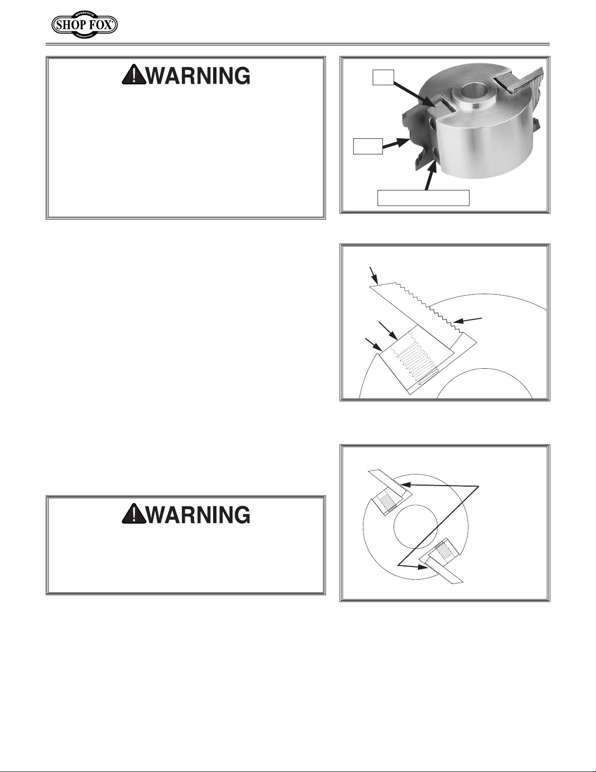
Gib
Knife
Set Screw (1 of 2)
Figure 2. Knife installed in moulding head.
Knife
(Top View)
2. While holding gib in moulding head, slide knife
corrugations into moulding head corrugations and
center knives on moulding head body. Make sure all
corrugations are engaged (see Figure 3).
3
3. Tighten set screws with a
⁄16" hex wrench, but DO
NOT over-tighten. Use only enough force to secure
knife snugly in position, so you can adjust knives in
next section.
4. Repeat Steps 1–3 to insert second knife in moulding
head. Make sure position of corrugations on first and
second knives is the same (see Figure 4) so both
knives are an equal height.
Improperly secured knives can fly out of moulding
head and hit operator or bystanders, causing
serious personal injury. Recheck all adjustments and
tightening sequences, and ensure both knives are
properly secured before installing moulding head.
Set Screw
Corrugations
Engaged
Gib
Moulding
Head
Figure 3. Moulding head corrugations
engaged.
Corrugations
Match
If you need help with your new moulding head, call our
Technical Support at: (360) 734-3482.
-2-
Figure 4. Position of knife corrugations
match.
Page 3

D1700/D1701 Moulding Head (Mfd. Since 10/94)
Adjusting Knives
1. DISCONNECT SHAPER FROM POWER!
2. Install moulding head onto spindle and secure as
detailed in your shaper manual.
3. Choose a reference point on first knife you installed,
and adjust spindle height until this point is even
with table top, as shown in Figure 5. (The reference
point can be the bottom corner of the knife or any
feature that allows vertical alignment with table
top).
Table Top
4. Adjust second knife until corresponding point on it is
same height as first one relative to table.
5. Tighten one set screw on a gib a small amount, then
tighten nearby set screw same amount. Repeat until
all set screws are tight on both gibs. DO NOT overtighten set screws.
Spindle Mounting Tips
• Mount moulding head as low as possible on spindle.
• Add a spacer(s) on top of moulding head to ensure
that spindle nut does not rest on moulding head
shoulder.
• Secure the moulding head assembly with a locking
washer and nut, or two nuts locked together.
• Ensure your shaper is in top running condition and all
guards are in place.
General Procedures
A wide selection of knife profiles make the moulding head
a versatile addition to your shaper. The moulding head
operates on the same principle as other shaper cutters
and can be used for straight shaping, as well as irregular
shaping. Since the moulding head is larger in diameter
than most cutters, it must be operated at speeds ranging
between 4,000 to 7,000 RPM. Please refer to your shaper
manual if you are unsure about operating speeds.
Reference
Points
Figure 5. Reference points on knives
aligned with table top.
ALWAYS feed stock against moulding head direction of
rotation. The moulding head must come to a complete
stop and SHAPER MUST BE DISCONNECTED FROM POWER
before making any inspections or adjustments.
-3-
Page 4

D1700/D1701 Moulding Head (Mfd. Since 10/94)
Straight Shaping
For straight shaping, use the fence assembly of your
shaper. Refer to the fence adjustment section in your
shaper manual for fence alignment instructions. Make sure
all guards are in position and functioning correctly.
To perform straight shaping, do these steps:
1. DISCONNECT SHAPER FROM POWER!
2. Select appropriate knife profile and install it into
moulding head (refer to Installing Knives on Page
2).
3. Secure moulding head onto spindle, then check
that moulding head rotates in desired direction and
knives are oriented correctly, as shown in Figure 6.
4. Adjust spindle height.
To reduce operator exposure to knives
and prevent laceration or amputation
injuries, make sure moulding head
comes to a complete stop and POWER
IS DISCONNECTED before making any
inspections or adjustments.
Outfeed
Fence
Cutterhead
Rotation
5. Position outfeed fence (see Figure 6) for depth of
cut.
6. Use hold-downs, jigs or anti-kickback devices to
secure workpiece during shaping operation. Refer to
shaper manual for specific safety information about
straight shaping operations.
7. Always make a sample cut on a piece of scrap wood
before shaping workpiece. Readjust moulding knives
if necessary.
8. Follow recommended operating procedures for
shaping end of stock. Refer to shaper manual for
specific safety information regarding this type of
shaping operation.
Feed
Direction
(Guards &
Anti-Kickback
Devices Removed
for Clarity)
Figure 6. Moulding head set up correctly
for straight shaping.
-4-
Page 5

D1700/D1701 Moulding Head (Mfd. Since 10/94)
Irregular Shaping
Irregular shaping (freehand) takes a high degree of skill
and manual dexterity to perform. The fence assembly is
not used in irregular shaping and should be removed. Rub
collars must be used. Choose the correct diameter for
the appropriate depth of cut. When doing freehand work,
a starting pin must be used. The purpose of the starting
pin is to support the workpiece. The starting pin acts as a
pivot point and gives the operator more control during the
beginning of the cut.
Rub collars can be positioned on top (see Figure 7) or
below the moulding head, depending on the type of work.
Plan ahead and determine which rub collar position will
work best for your needs.
To perform irregular shaping, do these steps:
1. DISCONNECT SHAPER FROM POWER!
2. Remove fence assembly.
To reduce operator exposure to knives
and prevent laceration or amputation
injuries, make sure moulding head
comes to a complete stop and POWER
IS DISCONNECTED before making any
inspections or adjustments.
• Always use starting pin/block and
rub collar for freehand work.
• Use guards and hold-downs, and
verify they function correctly.
• Follow all safety guidelines of
shaper manufacturer for freehand
work while operating shaper with
moulding head.
3. Choose appropriate moulding knives, secure in
moulding head (refer to Installing Knives on Page
2), then install rub collar and spindle nuts (see
Figure 7).
4. Check direction of moulding head rotation.
5. Lock spindle height after aligning knives to
workpiece.
6. Insert starting pin into table surface; choose
appropriate hole position. See owner’s manual for
location. If a starting pin is not available, use a
starting block, as shown in Figure 8.
7. Inspect stock or pattern for any irregularities which
may cause a miss-cut.
8. Use some type of hold-down(s), fixtures and guards
when performing freehand work (see Figure 8).
Rub Collar
Template
Workpiece
Figure 7. Rub collar positioned above
moulding head.
Moulding
Head
Spindle
Nuts
Starting
Block
Clamps
-5-
Workpiece
Figure 8. Typical setup for performing
irregular shaping.
Page 6

9. Place workpiece in starting position using starting
pin for support (see Figure 9).
10. Gradually swing work into moulding knives, keeping
workpiece against starting pin (see Figure 10).
D1700/D1701 Moulding Head (Mfd. Since 10/94)
Starting Pin
Workpiece
Figure 9. Workpiece in starting position
(Guard removed for clarity).
11. After workpiece is supported by rub collar, swing
workpiece free of starting pin (see Figure 11).
Always feed against rotation of knives.
12. Always make a sample cut on a piece of scrap wood.
Readjust moulding knives if necessary.
Figure 10. Swinging workpiece into knife
and against pin.
Figure 11. Feeding workpiece against
moulding head knife.
-6-
 Loading...