

Page 1

ShopBot PRS Assembly Manual Page -1
ShopBot PRS: Assembly Manual
These assembly instructions apply to both PRSalpha and PRSstandard models of ShopBot
CNC’s. Note that there are different sections for connecting each type of tool to the control
box. Make sure that you are using the correct connection section for your ‘alpha’ or
‘standard’ PRS model.
The boxes are very heavy! Several components are heavy! Make sure you have
help or proper handling equipment when moving or positioning boxes or parts.
PRSAssembly080922.doc Copyright 2007,2008 ShopBot Tools, Inc
Page 2

ShopBot PRS Assembly Manual Page -2
Contents
Assembly Manual .................................................................................................... 1
Table Surface Considerations..........................................................................................................................3
Electrical Precautions ......................................................................................................................................4
Overview of Your ShopBot PRS CNC Tool......................................................................................................5
Assembling Your ShopBot...............................................................................................................................7
Tools You Will Need..........................................................................................................................7
Unpacking and Getting Your Work Area Organized: .........................................................................8
Connection to Electrical Service......................................................................................................................9
Overview of the Assembly Process ...............................................................................................................10
Off and Running….........................................................................................................................................10
Assembling the Table ............................................................................................. 11
Table Parts............................................................................................................ 12
Assembly Steps ..................................................................................................... 14
Step1.1: Attach a Machine Glide to the Bottom of Each of the Table Legs....................................................14
Step 1.2: Attach the Table Legs to the Table Sides.......................................................................................14
Step 1.3: Attach the First Upper Table Support .............................................................................................16
Step 1.4: Slide the Cross Supports into Position ...........................................................................................18
Step 1.5: Working on the other End of the Table where the Legs are still temporarily attached to the Outside
of the Table Sides..........................................................................................................................................19
Step 1.6 Square and Level Table .............................................................................. 20
Table Surface (probably attach later?) ...................................................................... 21
Suggested Materials......................................................................................................................................21
Attaching the Table Surface...........................................................................................................................21
Installing the Gantry .............................................................................................. 23
Installing the X-Rails and Getting One Rail Straight ..................................................... 23
Slide the X-Rails onto the Table ....................................................................................................................23
Set the Front Side X-Rail and Check for Straightness...................................................................................23
Adjust the Position of the Rear X-Rail............................................................................................................24
Putting the X-Car on the Rails and Using it to Align the Rear X-Rail ............................... 25
Lower the X-Car onto the X-Rails ..................................................................................................................25
Use the X-Car as a Guide to Align the Rear X-Rail .......................................................................................26
Mounting the YZ-Car and adjusting its lower wheel bearings ........................................ 27
Place YZ-Car on the X-Car............................................................................................................................27
Attach the Lower Wheel Bearings on the YZ-Car ..........................................................................................28
Adjust the Lower Wheel Bearings on the YZ-Car ..........................................................................................29
Attaching the Motors .............................................................................................. 30
Put the Pinion Gears on the Motors...............................................................................................................30
Mount the Motors...........................................................................................................................................31
Set the Mechanical End Stops for the X Axis.................................................................................................33
Run the X-2 Motor Cable through the Aluminum Beam.................................................................................34
Mounting the Router or Spindle................................................................................ 35
If You Have a Porter Cable Router ................................................................................................................35
If You Have a High Frequency Spindle:.........................................................................................................36
After Mounting the Router/Spindle............................................................................ 37
Wheel Guards........................................................................................................ 37
Proximity Switches ................................................................................................. 38
Install the Proximity Switches ........................................................................................................................38
Y-axis Targets................................................................................................................................................39
X-Axis Targets. ..............................................................................................................................................40
Z-Zero Plate Holster ............................................................................................... 40
PRS Y-axis EChain Installation ................................................................................. 41
Secure cables and wiring......................................................................................... 46
Run the YZ Wiring .........................................................................................................................................49
Neaten up the Wiring at the Back Side of the X Car......................................................................................49
Create a Cable Loop on the way to the Control Box......................................................................................49
Hooking Up to the Control Box ................................................................................. 50
Do’s and Don’ts ..................................................................................................... 50
PRSAssembly080922.doc Copyright 2007,2008 ShopBot Tools, Inc
Page 3

ShopBot PRS Assembly Manual Page -3
Hooking Up Your PRSalpha ...................................................................................... 51
Powering the PRSalpha Control Box.............................................................................................................51
ShopBot Configuration PRSalpha: US Standard, 60Hz..................................................................51
ShopBot Configuration PRSalpha: European Standard, 50Hz .......................................................51
Mount the PRSalpha Control Box..................................................................................................................52
Explore the PRSalpha Control Box................................................................................................................53
Inside the PRSalpha Control Box ....................................................................................................54
Open the Roxtec Fixture................................................................................................................................55
Plug the Motor Cables into Drivers ................................................................................................................55
Connect the Emergency Stop Switch and the 3-Button Pendant...................................................................56
Installation .......................................................................................................................................57
Connect Cables from the Proximity Switch and Z-zero Plate.........................................................................58
Seal the Cable Entry......................................................................................................................................59
Ground the ShopBot PRSalpha.....................................................................................................................59
Connect the USB cable from PRSalpha Control Box to computer.................................................................60
Hooking Up Your PRSstandard ................................................................................. 61
Plug the Motor Cables into your PRS Standard Control Box .........................................................................61
Connect the Cable from the Remote-Stop Switch .........................................................................................61
Connect the Cables from the Proximity Switch and Z-zero Plate...................................................................62
Ground the ShopBot PRSstandard................................................................................................................62
Connect the USB cable from PRS Standard Control Box to the computer ....................................................63
The Remote Stop Switch...............................................................................................................................63
Mounting the Switch ........................................................................................................................63
If you use screws to mount the Remote Stop Switch:......................................................................63
Mission Accomplished! ............................................................................................ 64
Table Surface Considerations
You will need to supply sheet material for the deck of your table. We recommend 3 sheets
of material to give the table good rigidity. See discussion of the options at the end of the
Table Assembly section. As a start you will need one layer of cabinet grade ¾” plywood for
the bottom support layer – it will take several sheets to cover the work area if your tool is
larger than 4x8.
if you are installing a vacuum hold-down system, you will need to decide on specific
materials for your plenum and bleeder board.
PRSAssembly080922.doc Copyright 2007,2008 ShopBot Tools, Inc
Page 4

ShopBot PRS Assembly Manual Page -4
Electrical Precautions
MOTOR CONNECTIONS - DO NOT CONNECT OR DISCONECT ANY MOTOR WIRE
CONECTORS WHILE YOUR CONTROL BOX IS TURNED ON !! During the process of a
‘hot’ connect or disconnect there is a high load put on the motor driver circuitry which is
very likely to damage the motor driver. A damaged driver means that motor does not run
correctly. Also, do not unwrap the heat-shrink surround that keeps your motor cables
connected to the motors. It is intended to help keep all connections permanently secure.
STATIC DISCHARGES – Electronic circuits are very sensitive to static and power surges, and
your Control Box is no exception. Please have your electrician follow the wiring and
grounding instructions in the wiring section to help prevent static from damaging
components of your tool. In particular, avoid doing any vacuuming around your tool before
you have grounded both the tool and your vacuum system. Large static build-ups can occur
inside a vacuum collection system and discharge accidentally through the wiring of your
ShopBot.
INDUCED CURRENTS - The stepper motors on your tool become significant little generators
if they are manually turned. They can generate sizable voltages in your control box if you
push the X or Y-axis of your tool around physically. Occasionally it may be necessary to
move the tool by hand, but try to minimize such movement and when you must do it, make
the move slowly. If you need to do a lot of manual movement, unplug the motors on the
axis you are moving - having shut down the power first as noted above.
PRSAssembly080922.doc Copyright 2007,2008 ShopBot Tools, Inc
Page 5
ShopBot PRS Assembly Manual Page -5
Overview of Your ShopBot PRS CNC Tool
Note that the diagrams in this manual depict a generic ShopBot. Depending on the size and
shape of your tool, the table layout may look a little different (fewer or more legs, different
shape, etc.).
Before you unpack and start to assemble your ShopBot PRS tool, let's go over the some of
the major components and get familiar with the terminology and directions we'll be using:
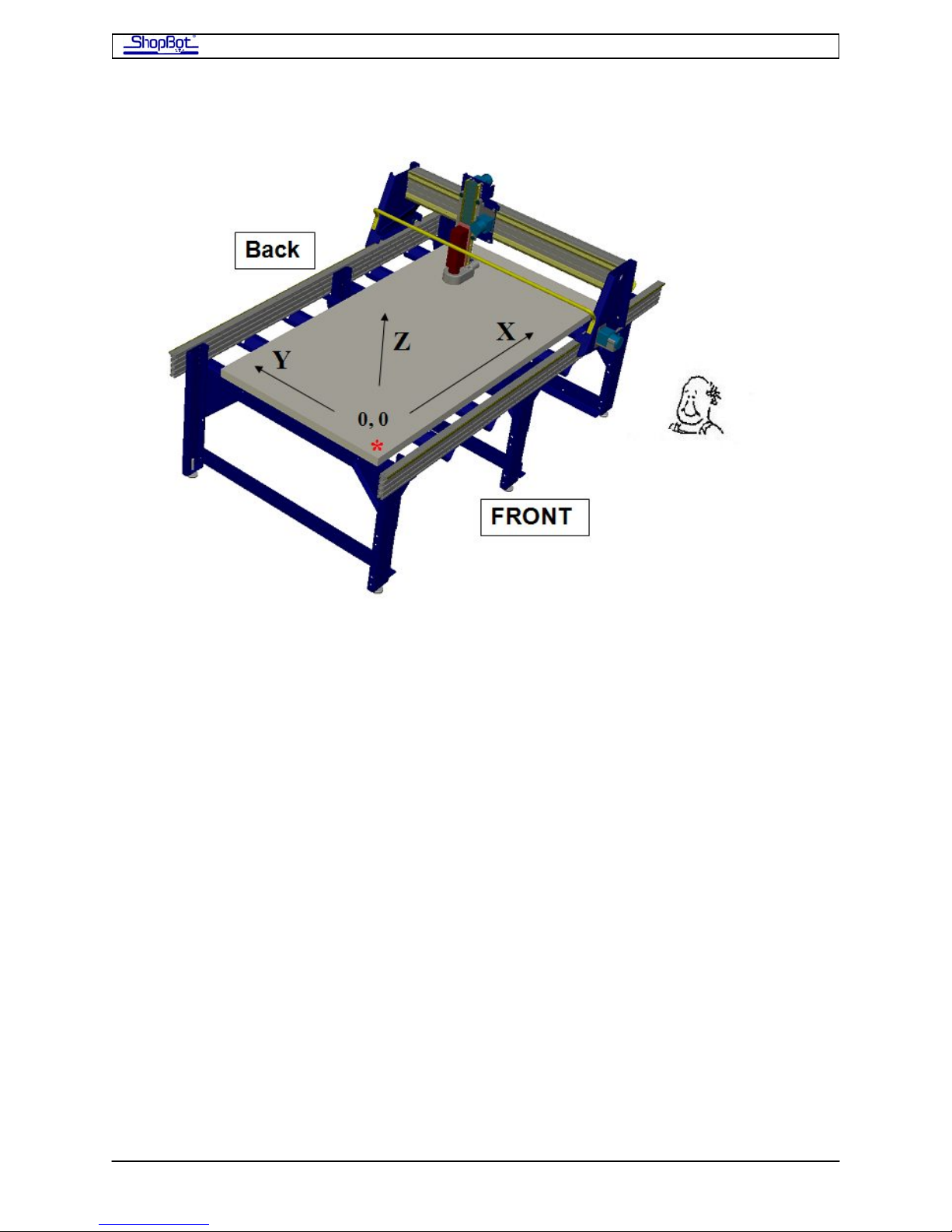
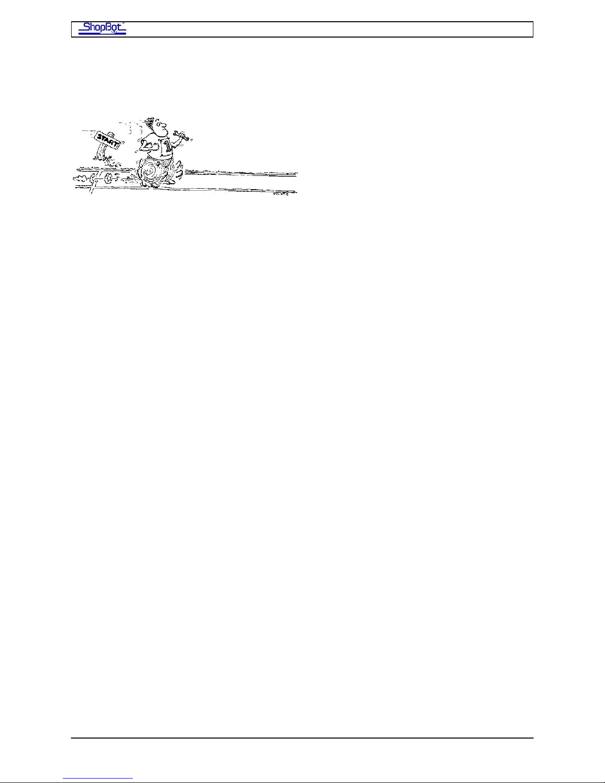
THE TABLE To get us located, refer to the orientation diagram above and imagine looking
at the tool from the position of the little man in the drawing. From this position, we'll call
the lower left hand corner of the work area the tool's 0,0 (or home) location. The X-axis is
the long length of the table and values increase going to the right from where you are
standing. The Y-axis is the narrow width of the table (or front to back from your position on
the long side) and values increase as you move away towards the back. The Z-axis is the
vertical movement or the plunging and withdrawal movement of your tool. Decreases in Z
values are plunges down by your cutting tool. Increases are movements of the cutting tool
up.
Still looking from the position of the little man, consider the furthest away X-axis track that
the bearings ride on to be at the back of the tool, the track nearest the little man to be at
the front, the left side the left, and so on. As you're positioning your tool in your shop, keep
in mind that you will typically be loading sheet material from the left or right side so you
should be sure to leave yourself some room to move around at one or both ends of the tool.
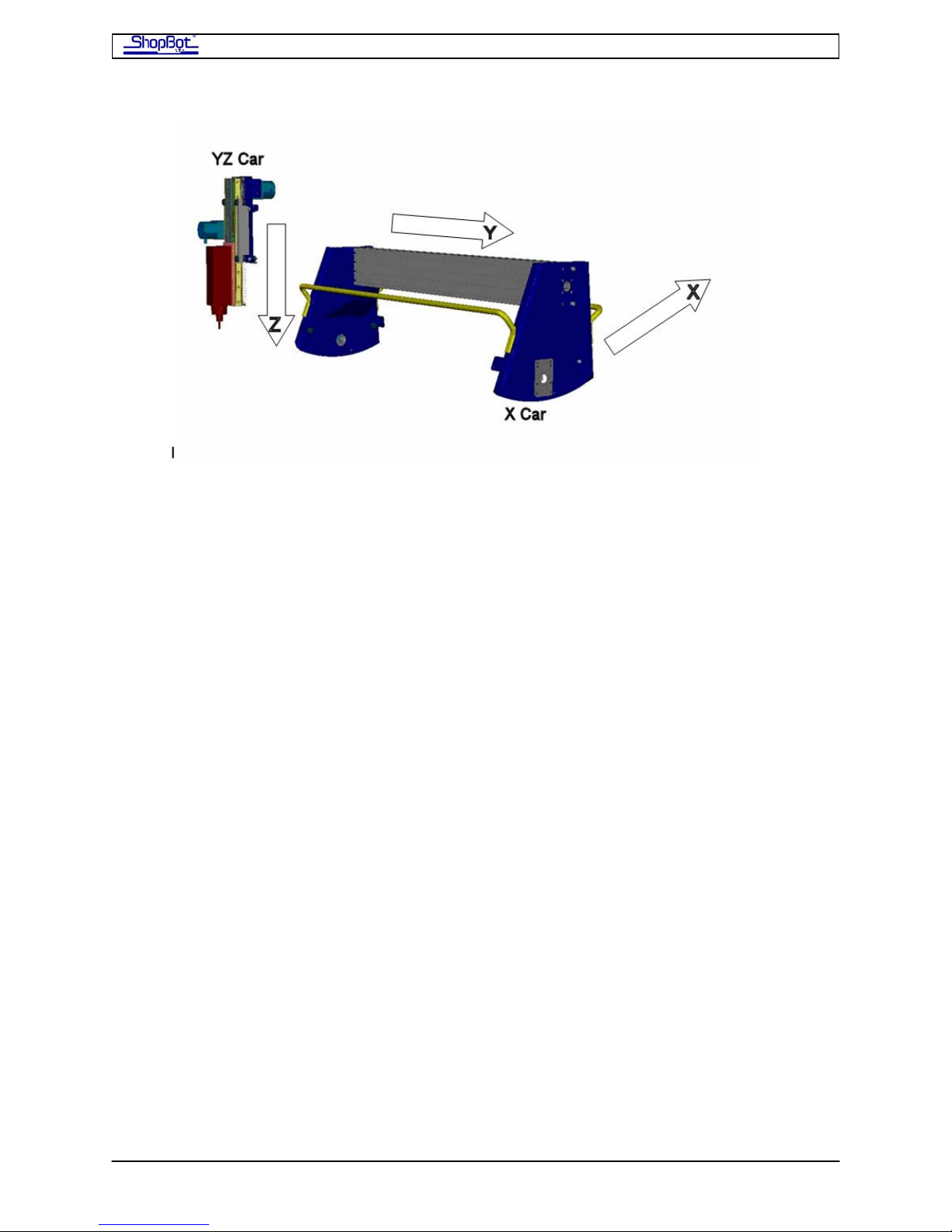
We'll use the words or 'car' to refer to the entire moving unit of a particular axis. The big
gantry is thus the X Car, and the one that rides on it, the YZ Car.
PRSAssembly080922.doc Copyright 2007,2008 ShopBot Tools, Inc
Page 6
ShopBot PRS Assembly Manual Page -6
The electrical cabling will be arranged along the back of the tool, so this is the part of the
tool that can be placed nearer a wall, obstruction, or where there will generally be less
action. Note, however, that it is best if you are able to walk around and access your tool
from all sides. The wiring for the Y and Z axes will be attached to a clear plastic Wire Guide.
The Wire Guide arches out from the back right hand corner of the X-Car to the front right of
the YZ-Car, as seen from the little man. Note that the X-Car mounts with the sloped side
(front of car) to the left.
THE X-AXIS. The X-axis is the basis for your tool's right and left moves (as seen by you as
the little man in the front of the diagram) -- it's the long axis on a standard ShopBot. Note
that the distance between the tracks on the X-axis is wide. Because of this span, we power
the X-Car movement with 2 motors, one on each side. The X-Car is driven by a rack and
pinion power transmission system. The gear rack is mounted on the bottom of the long X
rails and engaged by the pinion gear on the motor shaft.
THE Y-AXIS. The Y-axis provides the front to back movement of your ShopBot (the short
axis for a standard ShopBot). Note that the Y-axis rides on the X-axis. The gear rack for the
Y axis is mounted in the face of the X-Car beam.
THE Z-AXIS. The Z-axis is vertical, rides the face of the YZ-Car, and moves the cutting tool
up and down. The drive system for the Z-axis is also rack and pinion. The Z axis is springloaded to counterbalance the weight of your router or spindle.
THE ROLLING GEAR. Throughout your PRS ShopBot, precision motion bearings roll on
hardened stainless steel rails to provide your tool with smooth travel.
THE CONTROLS. Your ShopBot is moved and controlled by a personal computer (running
Windows XP or Vista) that you provide. In the ShopBot Control software, signals are
streamed from the PC's USB port through a USB cable to the ShopBot Control Box. The
Control Box is placed near the tool and provides the driving power to the motors. The
Control Box also receives incoming information from other devices such as your Z-Zero
Plate and Proximity Switches.
PRSAssembly080922.doc Copyright 2007,2008 ShopBot Tools, Inc
Page 7
ShopBot PRS Assembly Manual Page -7
Assembling Your ShopBot
Tools You Will Need
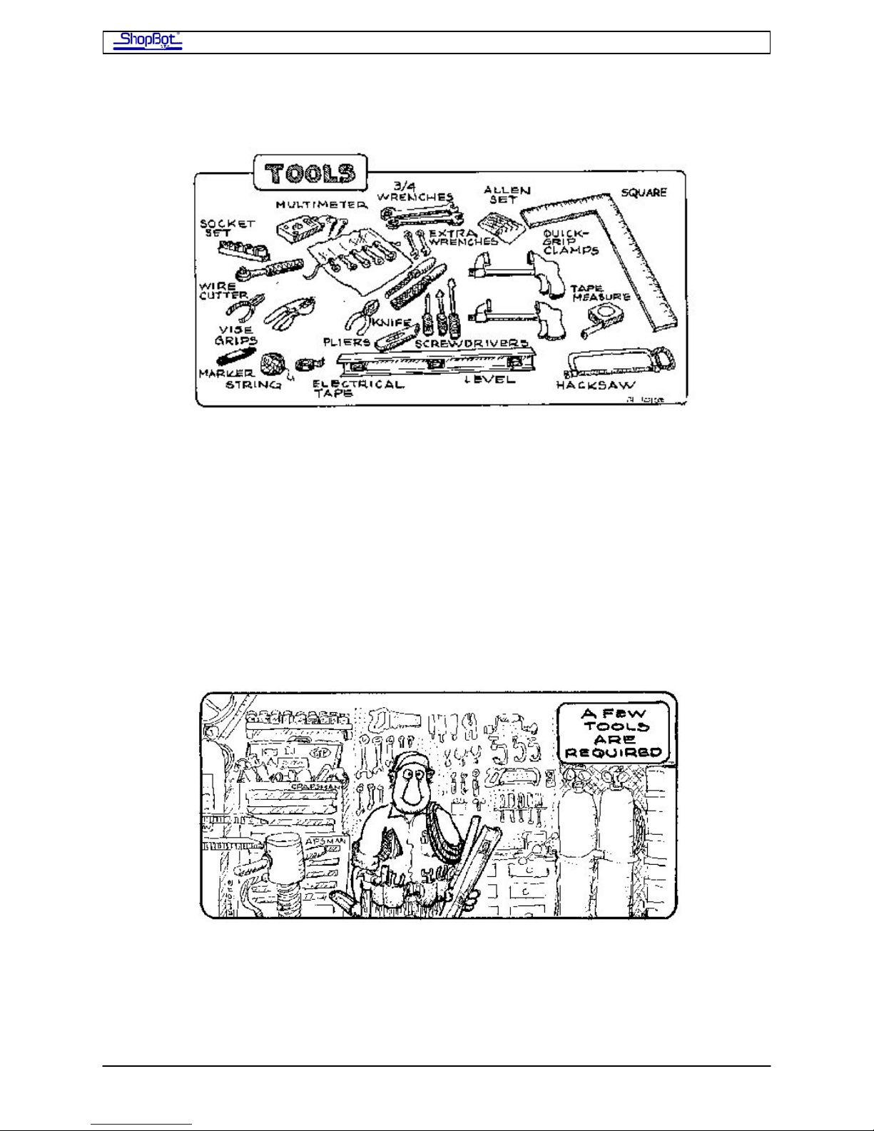
• a wrench set with TWO wrenches of the following sizes 7/16”, 1/2”, 9/16”, and
3/4”(the type with box end on one side and open end on the other works well).
• a socket wrench set with a 6” extension
• an Allen wrench set
• a drill for a couple of holes in the sheets of material you will use for your table
surface (say 1/4” and 7/16”)
• a good tape measure, a carpenter's square, and a level (a six foot one that you can
use for a straight edge would be good)
• several Quick Clamps or large C-clamps to temporarily hold things and act as STOPS
• Misc: the odd screwdriver, adjustable wrench and pliers, utility knife, electrical tape
(in a color that you can mark on) or masking tape, marking pen, your wits, etc.
PRSAssembly080922.doc Copyright 2007,2008 ShopBot Tools, Inc
Page 8
ShopBot PRS Assembly Manual Page -8
Unpacking and Getting Your Work Area Organized:
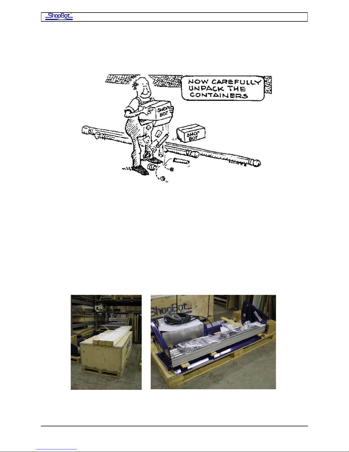
You will receive a large shipping crate with the already-assembled X-Car and YZCar. One of the large cartons inside the crate holds the ShopBot Control Box. The motors
and motor cables are packaged together. The long package with the rails and table sides
will usually be strapped to the top of the shipping crate.
You can unpack the rails and cars so that you can identify them and have them ready. Be
careful not to damage the gear rack on the bottom of the rails. Unpack and lay out the parts
bags on your work surface.
Don't worry about the Control Box for the moment; you can set it aside until we're ready to
connect your ShopBot.
We've pre-assembled most components of your tool to make things go a little more
smoothly. In many places, bolts or hardware are loosely fit in place to show you their
intended location; you may have to remove them to attach the part.
PRSAssembly080922.doc Copyright 2007,2008 ShopBot Tools, Inc
Page 9

ShopBot PRS Assembly Manual Page -9
By way of giving you a little guidance: It takes one of us about 6 hours to assemble a
ShopBot, so we think you should be able to put your ShopBot together over a pleasant
weekend if you've already read through this Assembly Manual. Of course, the IRS thinks
that preparing your 1040 should take 2 hours and 43 minutes, with a further 23 minutes for
copying, assembling, and mailing the form!!
There are several stages in the assembly process where having a helper or two will be
useful to you. In particular, you will want help unloading and unpacking, getting the table
assembly started, and putting the X-Car on the rails.
Please remember that several of the components are very heavy!
Connection to Electrical Service
The Control Box for a PRS alpha tool needs to be connected to your electrical service by a
licensed electrician. This connection can be made at any convenient time, before or after
you complete assembly of the tool. The electrician does not need to be present when you
plug the wiring from the tool into the Control Box. However, it may be best to wait until the
tool is assembled and in its final position before having the electrical service hooked up.
Waiting will allow you to make sure you have the Control Box positioned in the best location
for your tool. The complete wiring diagrams for connecting the Control Box can be found
inside the door of the Control Box and will be needed by the electrician to correctly wire the
box into the electrical service.
If you have purchased a high frequency spindle and/or a vacuum blower, these will also
need to be wired by a licensed electrician. The electrician will wire the spindle into the
Control Box and connect the appropriate electrical service. The electrician will also wire your
blower to the correct electrical service.
The Control Box for a PRSstandard tool plugs into a standard 110v/15A (or 220v
international) circuit. However, if you have spindle or blower, you should have an electrician
do the wiring for these accessories.
PRSAssembly080922.doc Copyright 2007,2008 ShopBot Tools, Inc
Page 10
ShopBot PRS Assembly Manual Page -10
Overview of the Assembly Process
Assembling the Table.
This has the most parts, the most steps, and will probably take the most time. A helper is
useful at the start, but not essential for this project. A couple of saw horses or other
supports will help you out. See the section of MEASURED ASSEMBLY DRAWINGS for your
specific size PRS (fixed table) for dimensions.
Installing the X-Rails and Gantry
Take your time to align the parts correctly. This is critical in terms of getting your tool
running true. You will need help to lift and position the X Car on the rails.
Attaching the Motors
Mounting Your Router or Spindle
Your cutting tool needs to be attached to the front of the Z axis beam. A helper is useful,
but not essential for this project.
Wheel Guards, Proximity Switches, Z-zero, and Echain
More to install, then tidy up all the wiring and make sure you are ready to roll.
Connecting Your Tool to the Control Box
Note there are different sections for the PRSstandard and the PRSalpha.
Off and Running…
Stopping the ShopBot
How to stop the ShopBot with the E-Stop, 3-Button Pendant, Remote Stop Switch and the
“S” key.
Taking a Test Drive
Ok, let’s go for a little spin, then we’ll review a couple of other things you will need to
attend to before you get into production.
Surfacing the Table Deck–
Here’s a first CNC project: Surfacing your table.
Squaring and Adjusting the X-Car
You shouldn’t need to adjust, but you will want to read about setting your End Stops
square.
Table Drawings with Measurements
Use the one for the size of the table you have.
PRSAssembly080922.doc Copyright 2007,2008 ShopBot Tools, Inc
Page 11
ShopBot PRS Assembly Manual Page -11
Assembling the Table
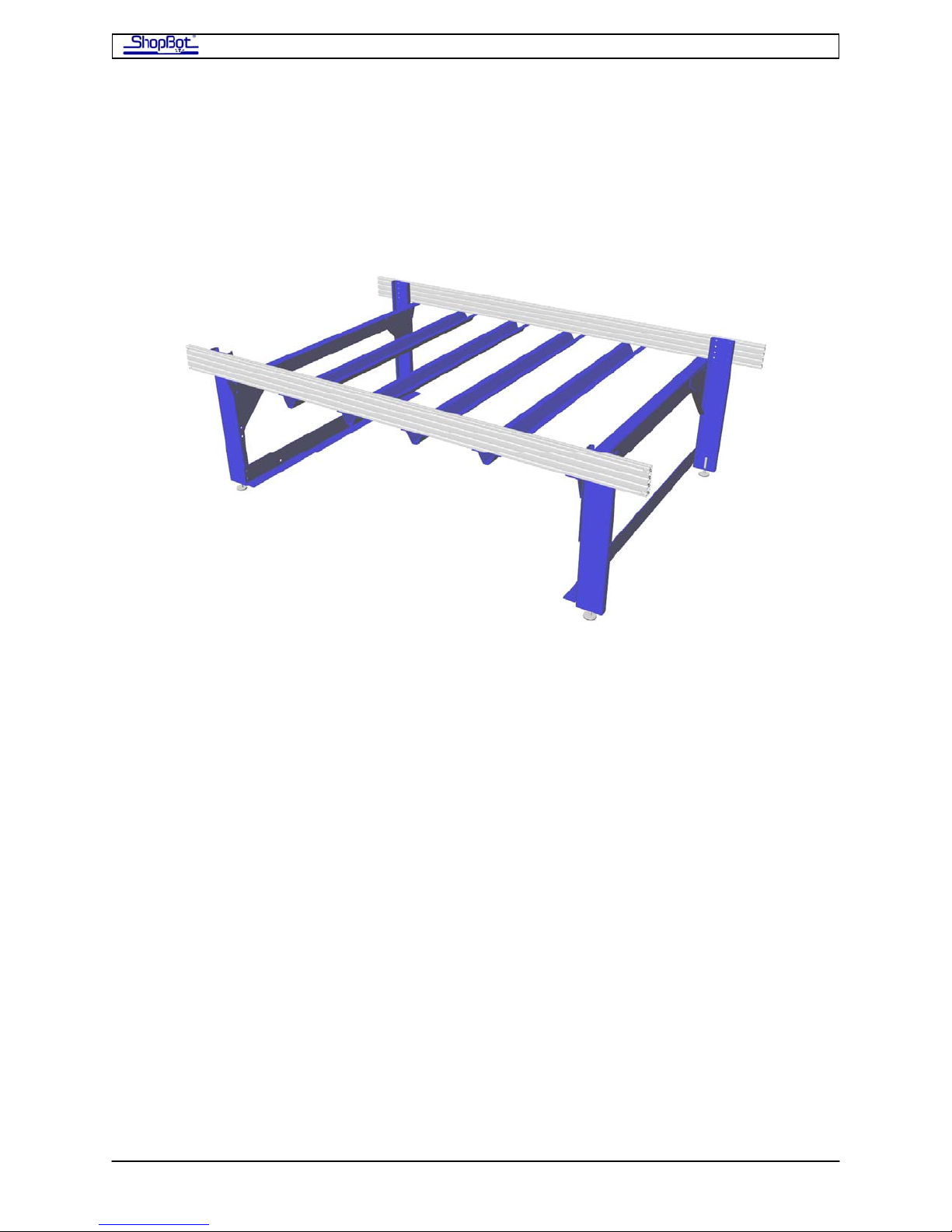
These are general assembly instructions for our steel and aluminum extrusion tables. For
specific dimensions and part identification, refer to the included Measured Drawing (located
at the back of this section) specific for the size ShopBot you are assembling. The Measured
Drawing plans show the dimensions of the tools, the spacing of the cross supports, and the
correct position for the table surface. NOTE that the number of legs on each side of the
table differs according to the size ShopBot you are assembling.
Take a look at Step 1.6 before you start. The goal of this assembly process is to have a
square and correctly dimensioned table at the end point. In the final step you will be
attending to getting the table square and the table sides exactly dimensioned for your tool.
PRSAssembly080922.doc Copyright 2007,2008 ShopBot Tools, Inc
Page 12
ShopBot PRS Assembly Manual Page -12
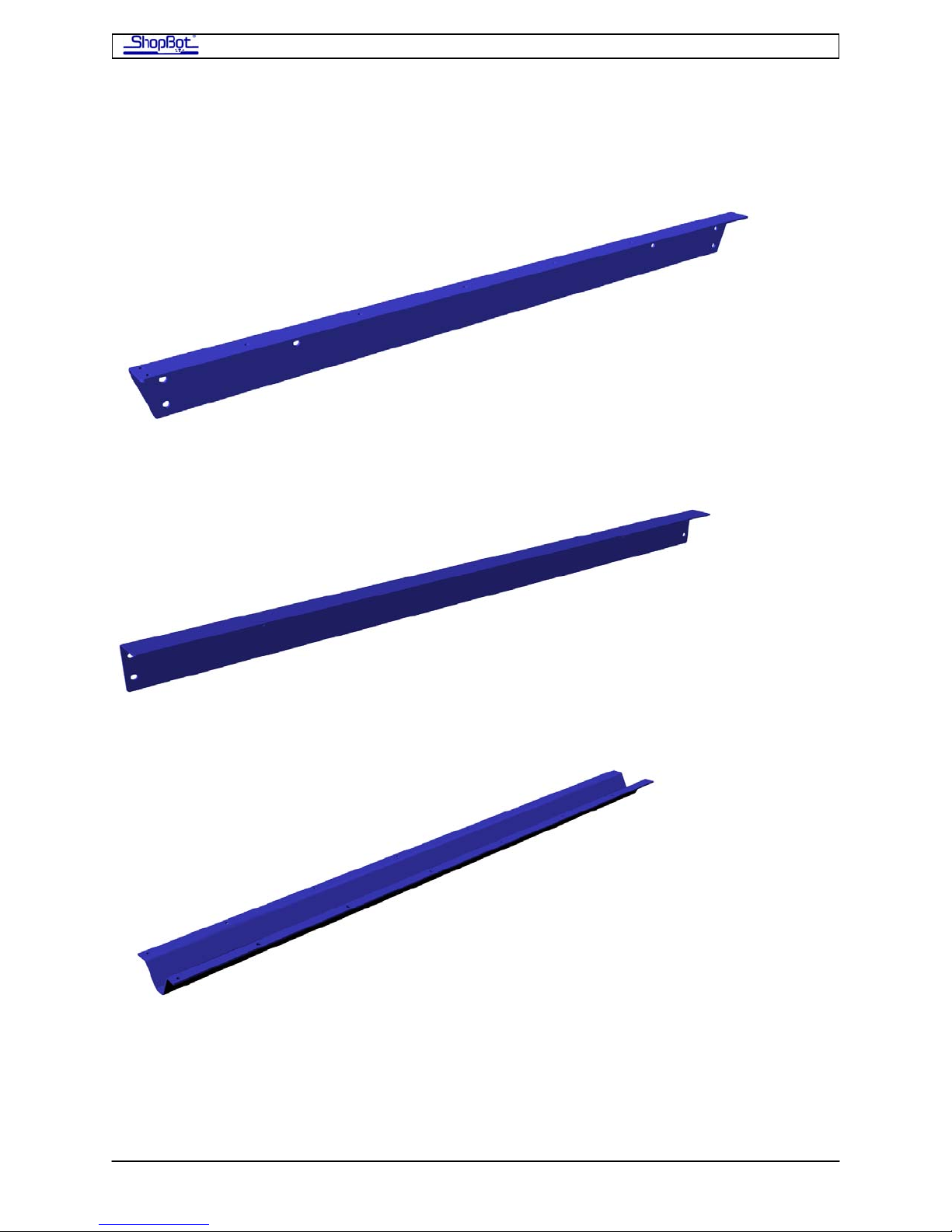
Table Parts
Upper Support (note beveled ends in upper support)
Lower Support
Cross Support
PRSAssembly080922.doc Copyright 2007,2008 ShopBot Tools, Inc
Page 13
ShopBot PRS Assembly Manual Page -13
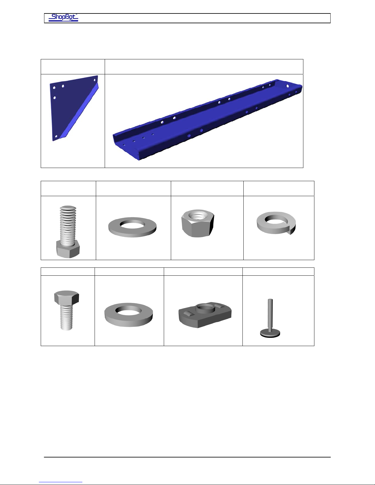
Table Gusset
1/2Bolt
Table Leg
1/2Flat washer
1/2Hex nut
1/2Lock Washer
5/16 Bolt 5/16 Flat washer Tee nut Machine Glide
(w 5/8 nut and
(in several sizes)
lockwasher)
PRSAssembly080922.doc Copyright 2007,2008 ShopBot Tools, Inc
Page 14
ShopBot PRS Assembly Manual Page -14
Assembly Steps
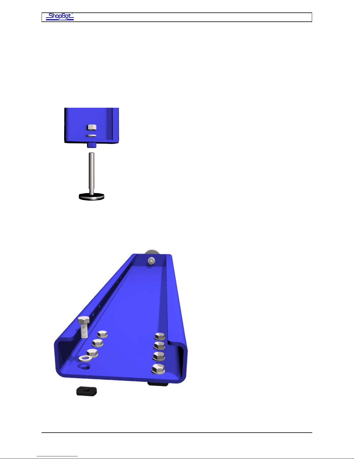
Step1.1: Attach a Machine Glide to the Bottom of Each of the Table
Legs
Screw a Machine Glide through the 5/8” nut in the bottom of each Table Leg. Place a 5/8”
lock washer and hand tighten a 5/8” hex nut on the Machine Glide. Do not tighten at this
time (see Step 5). Repeat for all legs.
Bottom of Table Leg showing Machine Glide assembly
Step 1.2: Attach the Table Legs to the Table Sides
Place 5/16” bolts, flat washers and T-nuts at the eight holes on each of the Table Legs.
Looking down on table leg
Attach the first leg to the inside of the Table Side by sliding the T-nuts into the side
channels on the Table Side. Square the Table Leg to Table Side and tighten just enough to
PRSAssembly080922.doc Copyright 2007,2008 ShopBot Tools, Inc
Page 15

ShopBot PRS Assembly Manual Page -15
hold the pieces securely in place. Keep in mind that you will want to tighten all nuts
securely at the end of the table assembly when you square the table. If you tighten all
fasteners too much now, you won’t be able to square the table later.
Temporarily attach the other Table Leg to the outside of the Table Side. This leg will be
moved to the inside of the table in Step 1.4.
Repeat for the other Table Side. Use saw horses to temporarily support the side assemblies
as you continue.
Table Sides with legs attached
PRSAssembly080922.doc Copyright 2007,2008 ShopBot Tools, Inc
Page 16
ShopBot PRS Assembly Manual Page -16
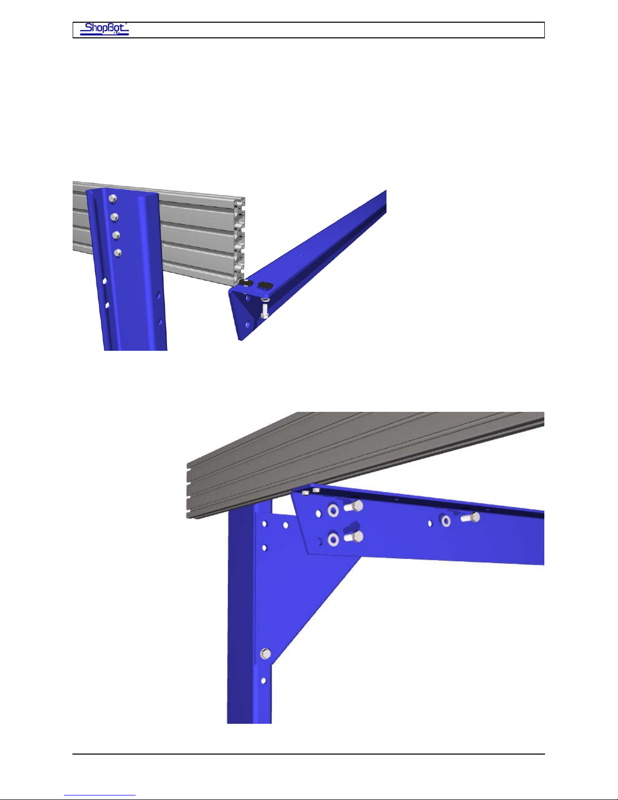
Step 1.3: Attach the First Upper Table Support
Attach the first Upper Table Support to the end of the table. Start it on from the side with
the temporary outside leg. Slide the T-nuts for the Upper Table Support into the bottom
channel of each Table Side on the far end. Then slide the Support all the way down and
close to the Table Leg, leaving approximately 3/16” between the leg and the upper support
for the Gussets.
Insert the Gussets between the Table Legs and the Upper Table Support and attach using
½” Hardware Assemblies.
PRSAssembly080922.doc Copyright 2007,2008 ShopBot Tools, Inc
Page 17
ShopBot PRS Assembly Manual Page -17
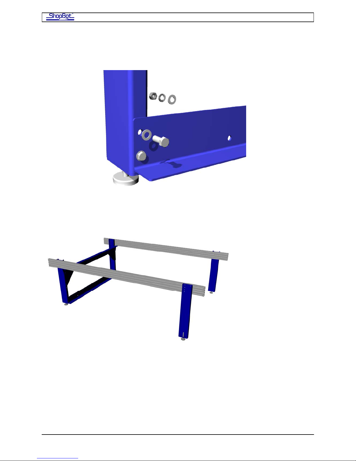
Attach the Lower Table Support to the bottom holes in the Table Legs using ½” Hardware
Assemblies.
Lower Table Support showing attachment to Table Leg.
.
Your table should now look like this:
PRSAssembly080922.doc Copyright 2007,2008 ShopBot Tools, Inc
Page 18

ShopBot PRS Assembly Manual Page -18
Step 1.4: Slide the Cross Supports into Position
Attach two 5/16” Hardware Assemblies to each end of the Cross Supports. Then slide the Tnuts into the bottom channels of the Table Sides and slide the Cross Supports into position.
Refer to the Measured Drawing for your table size for proper spacing of the Cross Supports.
Cross Supports in position
PRSAssembly080922.doc Copyright 2007,2008 ShopBot Tools, Inc
Page 19
ShopBot PRS Assembly Manual Page -19
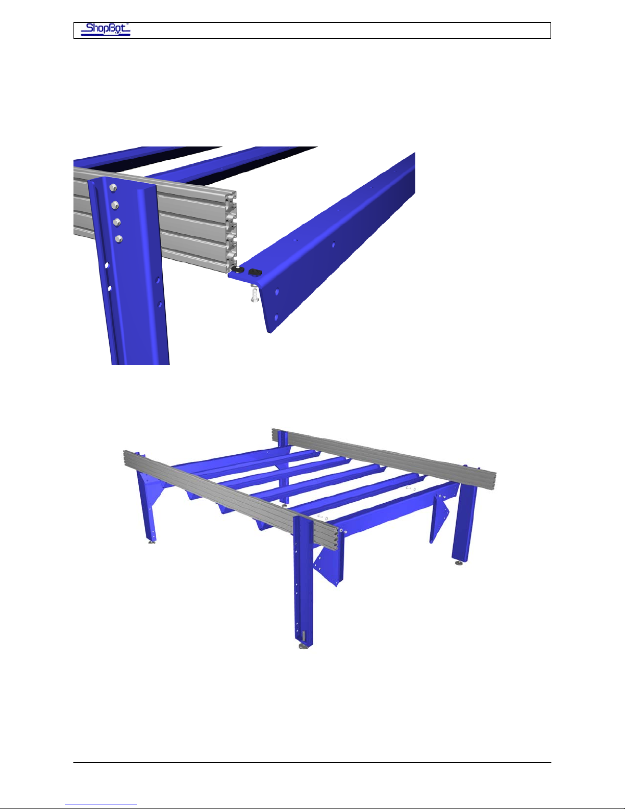
Step 1.5: Working on the other End of the Table where the Legs are
still temporarily attached to the Outside of the Table Sides
Install 5/16” Hardware Assemblies on the Upper Table Support and slide it into position.
Notice that the lead edge of the support inserts first, this time
Attach the Gussets on this end to the Upper Table Support . Use ½” Hardware Assemblies.
Your table should look like this.
Move these Table Legs to the inside.
Attach the Lower Table Supports to the bottom holes in the Table Legs using ½” Hardware
Assemblies. Attach remaining bolts on gussets.
Your table should now look like this:
PRSAssembly080922.doc Copyright 2007,2008 ShopBot Tools, Inc
Page 20
ShopBot PRS Assembly Manual Page -20
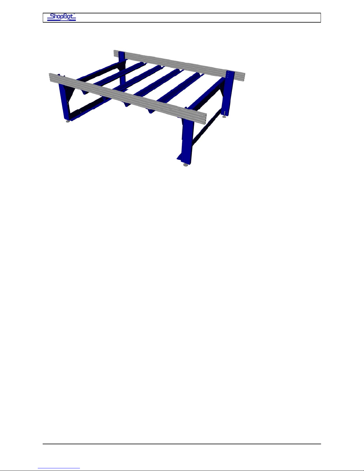
Step 1.6 Square and Level Table
Set the table where it will be used. Plan to spend a little time getting it square and adjusted
to the exact correct width measurement. [SEE DRAWING & TABLE BELOW]
Set the legs perpendicular to the Table Sides with a square and tighten.
Level the tops of the Table Sides across and diagonally using the Machine Glides. Then
tighten the 5/8” nuts on the Machine Glides.
Measure the table across both diagonals. If the measurements are not the same, the table
is not square. You will need to shorten the longer diagonal by one-half the difference of the
two diagonal measurements. With a mallet or hammer & protective block of wood, gently
tap the end of the table side at one end of the longer diagonal to shorten as needed. Adjust
the table until the measurements across the diagonals match.
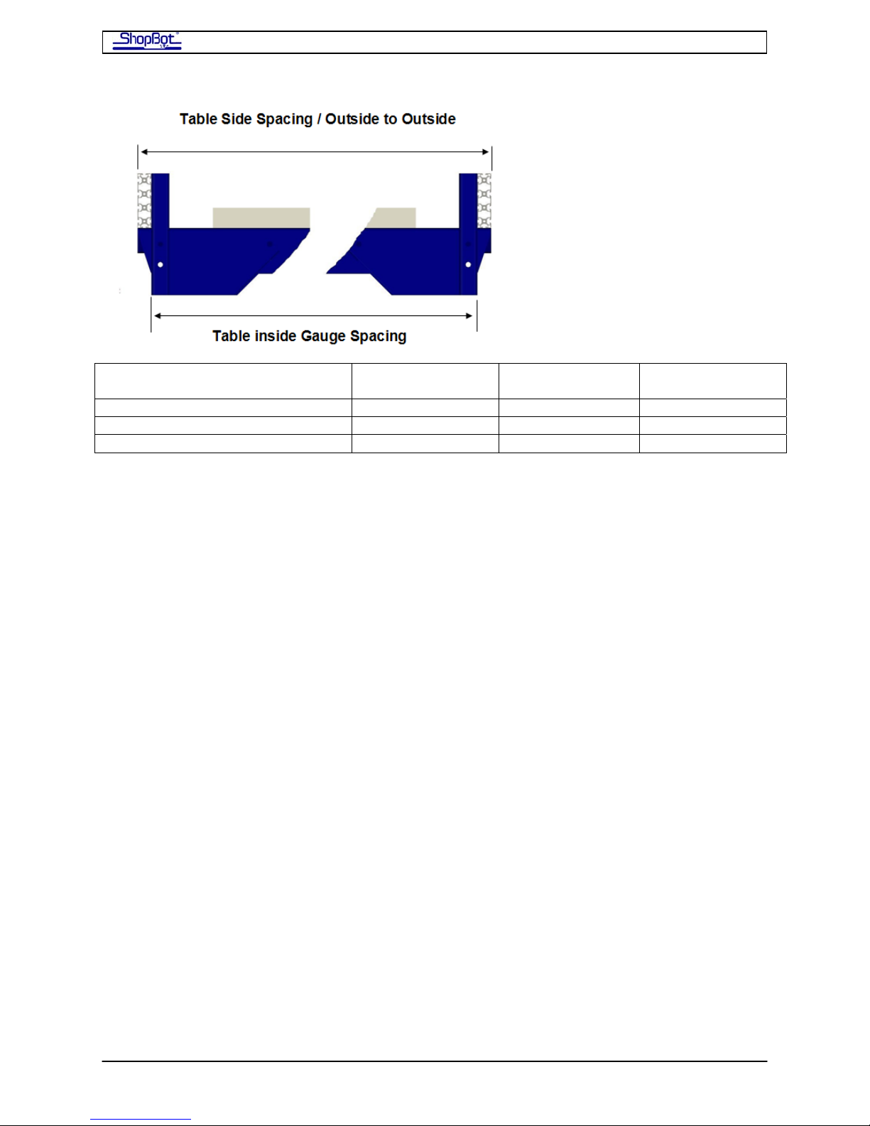
Then, work to adjust the distance between the rails to the exact spacing indicated in the
table below. It can be helpful to cut a measurement gauge from a 2x4 to use to set the
distance between the table sides. Make sure the gauge distance is right and giving you the
correct outside to outside measurements.
Tighten all hardware once the table is measured and square. Check the diagonals and the
distances frequently as you move around the table tightening the bolts.
PRSAssembly080922.doc Copyright 2007,2008 ShopBot Tools, Inc
Page 21
ShopBot PRS Assembly Manual Page -21
========== WORK AREA
WIDTH
DIMENSION 48” (121.92cm) 60” (12.40cm) 72” (182.88cm)
Outside to Outside of Table Sides 64.5” (163.83cm) 76.5”(194.31cm) 88.5”(234.79cm)
Gauge between Rail Spacing 61.5”(156.21cm) 73.5”(186.69cm) 85.5”(217.17cm)
==========
Table Surface (probably attach later?)
The deck surface of your table is created from several sheets of plywood or MDF. It makes
logical sense to consider how you will install the deck at this time, but most customers find
it more convenient to wait to do the final attachment of the table surface until after the tool
is fully assembled. At the moment, you’ll probably want to just lay a sheet or two of
plywood onto the cross supports to use as a work area. But we’ll explain the table surface
now.
Suggested Materials
For your Table Surface or Deck we recommend 3 layers of material to provide good rigidity.
• Support Board (bottom layer)
¾” Shop grade or cabinet grade plywood or better (birch, maple, poplar…hardwoods)
• Plenum Board or 2nd Layer if not installing a Vacuum System
¾”Medium Density Fiberboard (MDF) or
¾” High Density Polyethylene (HDPE) or
Another sheet of ¾” plywood if not installing vacuum
• Spoil Board
½” LDF or
5/8” MDF surfaced on both sides to a thickness of 3/8” or
½”-¾” MDF if not installing vacuum
Attaching the Table Surface
Refer to the Measured Table Drawing for your tool for positioning information for the table
surface. The drawings also show how to position multiple sheets if your table is larger than
4x8. You will center the support board(s) in the X direction. There should be about 1.5” of
material past the end support at each end. In the Y direction if your material exactly
PRSAssembly080922.doc Copyright 2007,2008 ShopBot Tools, Inc
Page 22
ShopBot PRS Assembly Manual Page -22
matches the tool’s work area, center the support board(s) in the Y direction between the
front and back table sides. For example, for a 4x8 tool, a 4x8 sheet should be exactly
centered. If your sheet material is oversize, then for all tool sizes locate the front side of the
sheet 6.75” in from the front side of the tool.
Clamp the sheet(s) in position, then attach through the holes in the cross supports with the
3/8” by 1.5” carriage bolts that are included in your parts. Use, every-other diagonal hole in
an alternating pattern in the Center Cross supports; every hole in the end supports.
From under the table, at each hole in the Upper End Cross Supports and alternating holes in
the center Cross Supports, drill a ⅜” hole through the Support Board
Countersink the holes on the top of the Support Board with a spade bit.
Insert the ⅜” x 1½” carriage bolts down through the Support Board, Upper End Cross
Supports or center Cross Support and attach with flat washers, lock washers and nuts.
If you are putting a vacuum hold-down system on your ShopBot. Please see the
documentation for the vacuum hold-down system for more information on installing your
plenum and bleeder board.
If you are not installing vacuum. Then attach a second layer to the support layer board
using countersunk drywall or plastic screws. When your tool is operational, you will be able
to surface this layer, and then attach a final sacrificial or working layer to your table.
The choice of actual material and methods for attaching your table depends on the nature of
work you will be doing, the kind of hold-down system that you use, and the experiences
that you gain with various materials. Your table surface is likely to evolve over time.
PRSAssembly080922.doc Copyright 2007,2008 ShopBot Tools, Inc
Page 23
ShopBot PRS Assembly Manual Page -23
Installing the Gantry
Installing the X-Rails and Getting One Rail Straight
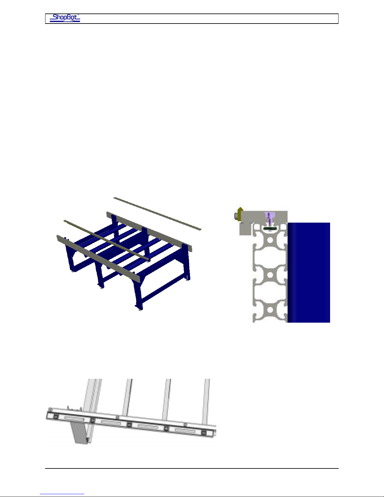
Slide the X-Rails onto the Table
• Mount the X-rails with 5/16 bolts and T-nuts. Slide these nuts into the top track of the
table sides as you did with the table legs and cross supports.
• After you get both rails in position, hand-tighten the bolts.
• BE CAREFUL SLIDING THE RAILS ONTO THE TRACK. IT IS VERY EASY TO PINCH
YOUR FINGERS WHEN INSERTING THE NUTS INTO THE TRACKS AS YOU SLIDE
THE RAIL ON.
Set the Front Side X-Rail and Check for Straightness
PRSAssembly080922.doc Copyright 2007,2008 ShopBot Tools, Inc
Page 24
ShopBot PRS Assembly Manual Page -24
• With bolts “finger tight,” move along the X-Rail on the front side of your tool,
aligning the aluminum bar on the inside exactly flush with the inside of the table
side.
• Then start at one end further tightening the bolts.
• As you continue to lock the front X-Rail in position, slide your 6ft level or straight
edge along the outside edge of the rail to check for straightness. Nudge the
aluminum bar slightly if it needs adjustment.
• When you’ve got the front side rail in position and straight, fully tighten all the bolts
on the front side rail.
Adjust the Position of the Rear X-Rail
You’ll use a tape measure to set the initial position of the rear X-Rail. Always make these
kinds of important measurements from the 1” mark on the tape. Do not trust the accuracy
of the clip at the end of the tape.
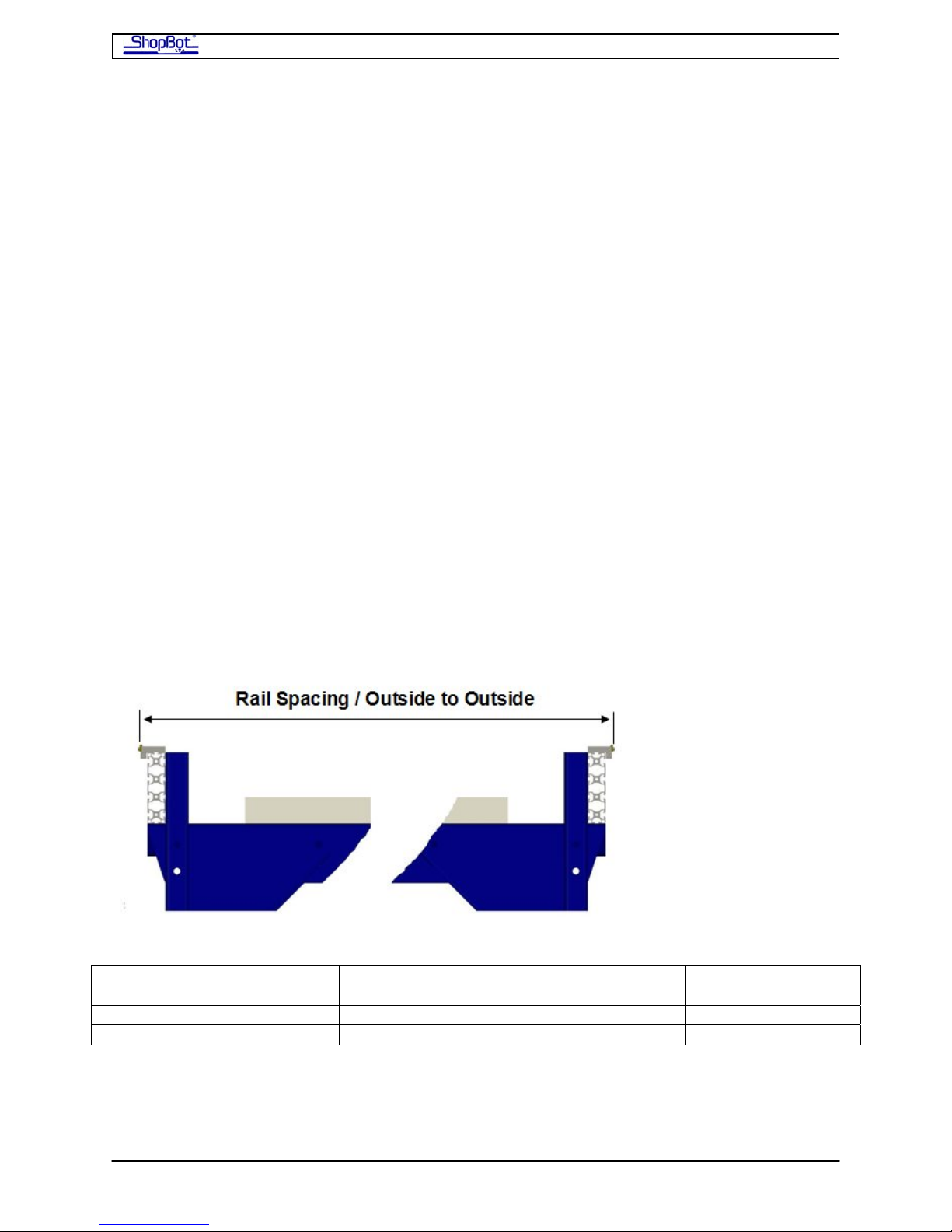
• Consult the chart below for the exact distance, outside edge to outside edge, for the
rails.
• Use the tape to check the distance at each of the bolts, and adjust where necessary.
Try to get within 1/32in of the distance. Note that the edge portion of the rails is ¼”
wide, so there will be a 1/16” mark that should fall on the exact centerline of the ‘V’
of the rail.
• Tighten these bolts on the rear rail down just a bit. But note that you are probably
going to need to adjust the rear rail again slightly, after putting the X-Car in place.
========== WORK AREA WIDTH ==========
DIMENSION 48” (121.92cm) 60” (12.40cm) 72” (182.88cm)
Outside to Outside of Rail 65.812”(167.16cm) 77.812”(197.64cm) 89.812”(228.12cm)
Outside to Outside of Table 64.5” (163.83cm) 76.5”(194.31cm) 88.5”(234.79cm)
PRSAssembly080922.doc Copyright 2007,2008 ShopBot Tools, Inc
Page 25
ShopBot PRS Assembly Manual Page -25
Putting the X-Car on the Rails and Using it to Align the Rear
X-Rail
Lower the X-Car onto the X-Rails
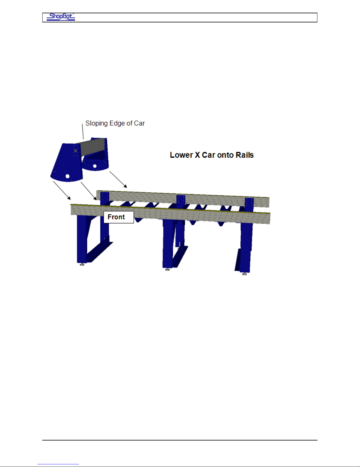
The X-Car is fully assembled and ready to be placed on the rails. This is a 2-4 person
operation as the car is HEAVY! Note that the car goes on the rails so that the sloping edge
of the X-Car faces towards the left when you are at the front of the tool.
• As you put the car in position, seat the wheel bearings on the front side X-Rail and
then place the rear bearings over the rear X-Rail. You may find it easier to lay the
Car over on its back first, with the beam across the rails and engaging only the
bearings on the back of the X-Car. Then, when you are ready, you can stand it up
and engage the wheel bearings on the Car’s front end. You may need to loosen the
rear X-Rail at this point and adjust it slightly so that the bearings come into exact
alignment.
PRSAssembly080922.doc Copyright 2007,2008 ShopBot Tools, Inc
Page 26
ShopBot PRS Assembly Manual Page -26
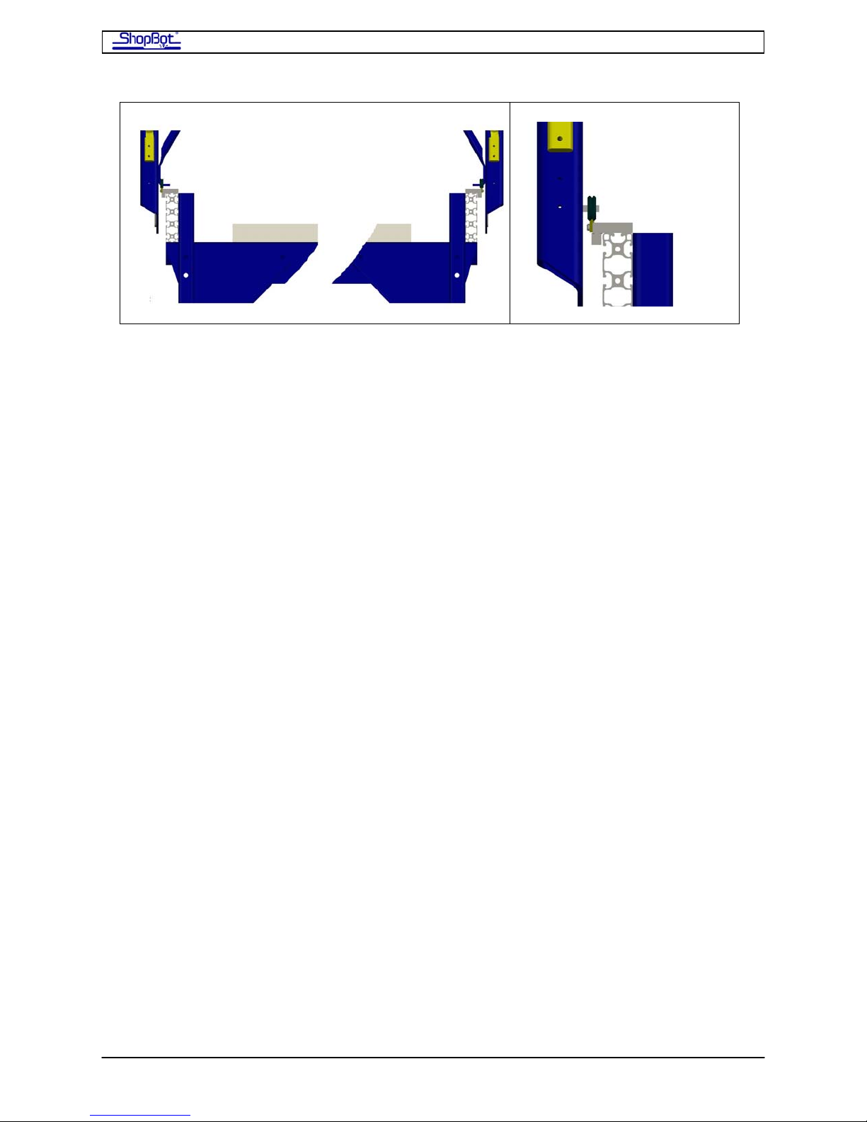
Detail
• Put a C-Clamp across the rails at each end of the table to create a temporary end
stop to prevent the X-Car from rolling off the table while you are carrying out the
next tasks!
Use the X-Car as a Guide to Align the Rear X-Rail
Note that the weight and rigidity of the cars, their wide wheel base, and the selfcentering nature of the V-groove wheels will take care of slight errors in the rails,
but you want to get the rails as well aligned as you can.
• Roll the car down to the middle bolt of the X-Rail so that you start the process from
the center of the table and work out to the ends.
• Clamp the side of the X-Car on the straightened, front rail so that the wheel bearings
are centered and locked onto the rails.
• Move back to the rear rails. Loosen up all the bolts a tad. Then make whatever
adjustment is needed to get the rails perfectly under the rear bearings.
• Work on this progressively over the rear rails, moving out from the center. There
should be enough adjustment in the rail to allow you to get the rear rail perfectly
aligned over its full length.
This is the hardest step, so take a deep breath and congratulate yourself when
you’ve gotten it accomplished!!!
PRSAssembly080922.doc Copyright 2007,2008 ShopBot Tools, Inc
Page 27
ShopBot PRS Assembly Manual Page -27
Mounting the YZ-Car and adjusting its lower wheel bearings
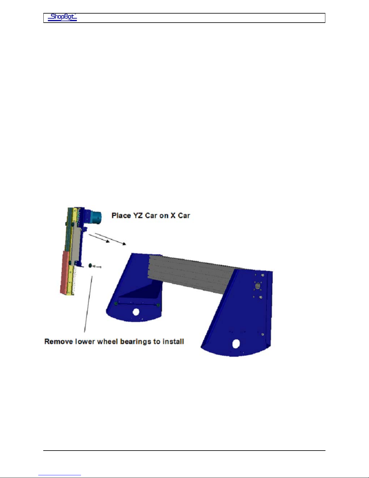
Place YZ-Car on the X-Car
The YZ-Car is a single piece that is ready to be placed onto the rails that cross the face of
the X-Car beam.
• Roll the X-Car up to the far left side of the table and clamp it in place to make the
installation easy.
• Remove the lower wheel bearings before setting the YZ-Car in place. Notice that
these bearings are on an eccentric (adjustable) bushing and that there is a small,
precision washer behind the bearing and bushing. This washer is critically important.
• After you have removed the lower bearings, lower the YZ-Car down onto the rail,
seating the upper bearing wheels on the upper Y-Rail. The car will sit in place on
these top bearings.
PRSAssembly080922.doc Copyright 2007,2008 ShopBot Tools, Inc
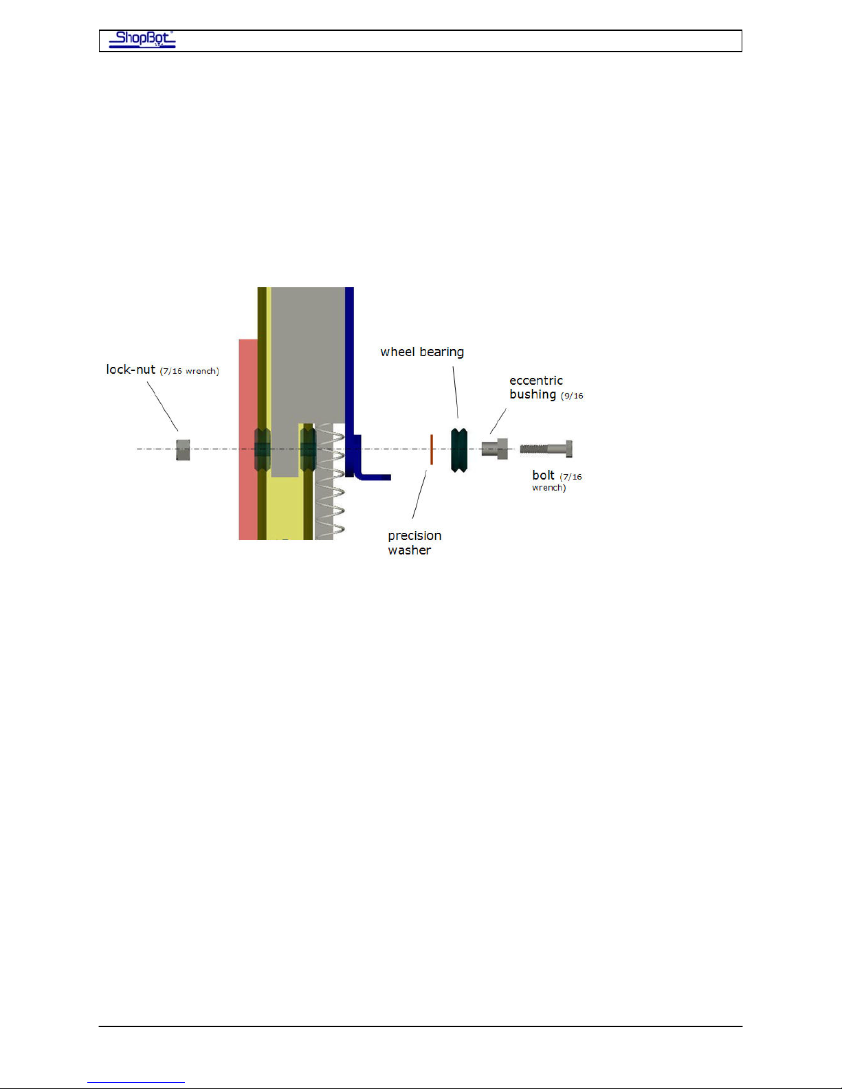
Page 28
ShopBot PRS Assembly Manual Page -28
Attach the Lower Wheel Bearings on the YZ-Car
With the YZ-Car in position riding on its upper wheel bearings, you can install the lower
bearings. Study the diagram below because the parts in this assembly need to be installed
exactly as indicated. Note that the assembly incorporates an eccentric bushing (having an
off-center hole), which will be used for the final adjustment of the bearing. This bushing has
a small precision washer behind it. This washer is critical for the alignment of the car and
for the normal operation of the bearing. (We’ve put extras in the “Extra” bag, just in case
you might drop one.)
• Insert the bushing into the wheel bearing, then insert the bolt so it protrudes just far
enough through the bushing to hold of the precision washer.
• The trick to the whole operation is to slide the wheel in from the side of the car, after
you have placed the ‘V’ of the wheel over the track. When you get the wheel directly
behind the hole in the car, push the bolt through.
• After pushing the bolt into place, put the washer on, and start the lock-nut. Leave
the assembly loose while you install the wheel bearing on the other side.
• When both wheels are in place, make sure that both are fully seated on the rail.
• Find the black mark on the edge of the eccentric bushing indicating the narrowest
spot. Put this side closest to the rail. Then, tighten down the ¼” bolt with 7/16”
wrenches.
PRSAssembly080922.doc Copyright 2007,2008 ShopBot Tools, Inc
Page 29
ShopBot PRS Assembly Manual Page -29
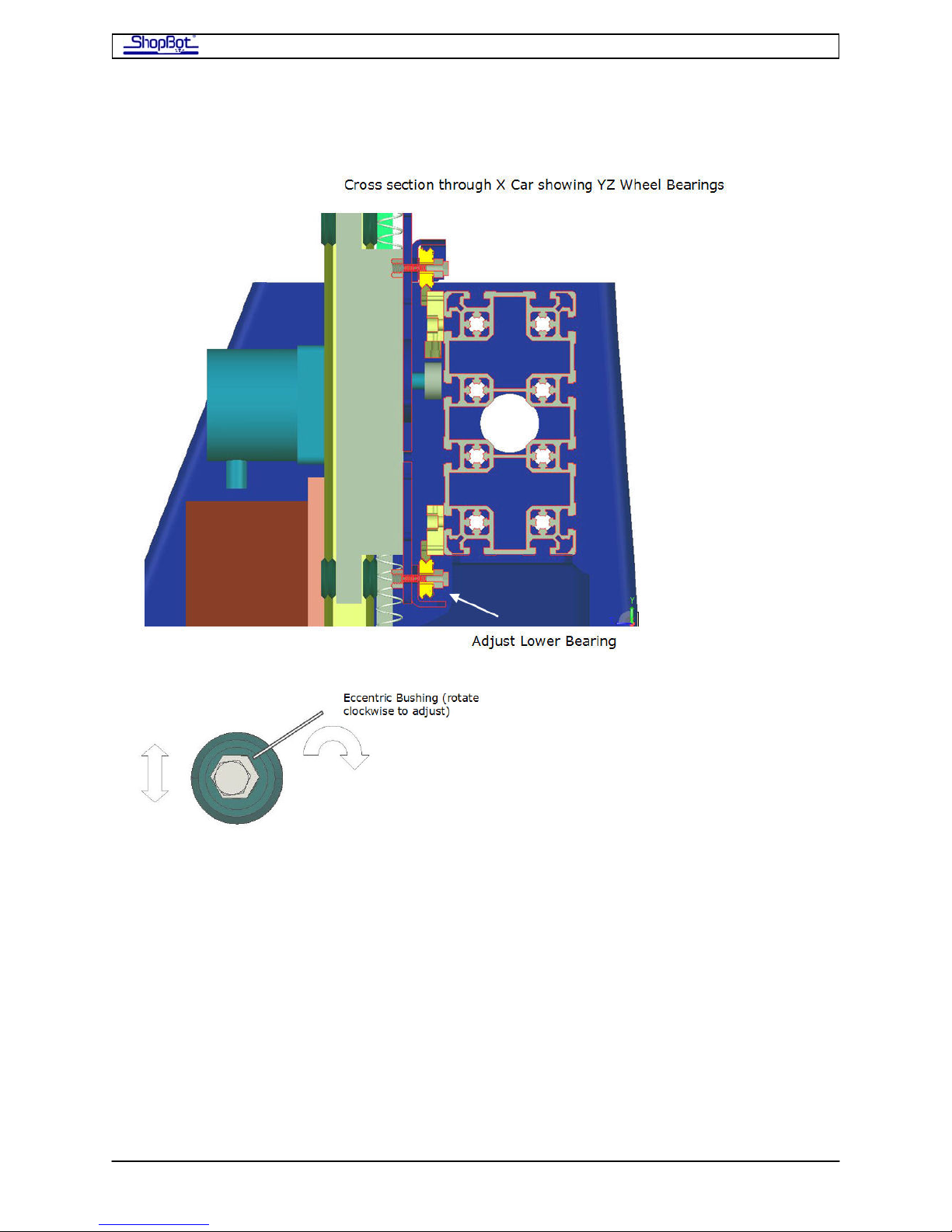
Adjust the Lower Wheel Bearings on the YZ-Car
The lower bearing is adjusted tight by rotating the eccentric bushing. It has an off-center
hole so that rotating the bushing moves the wheel into and out of contact with the rail. The
adjustment is done most easily with a 9/16” socket on a wrench with a 6” extension.
• Rotate the bushing in a clockwise direction in small increments until it fully engages
the rail. Push the YZ-Car back and forth from the front to make sure the wheel is
tightly engaged and there is no wiggle, but do not over-tighten.
• Check your adjustment over the entire rail. You should not be able to stop the wheel
from turning with finger pressure. It can be tight enough to produce a slight amount
of resistance to rolling.
PRSAssembly080922.doc Copyright 2007,2008 ShopBot Tools, Inc
Page 30
ShopBot PRS Assembly Manual Page -30
Attaching the Motors
Put the Pinion Gears on the Motors
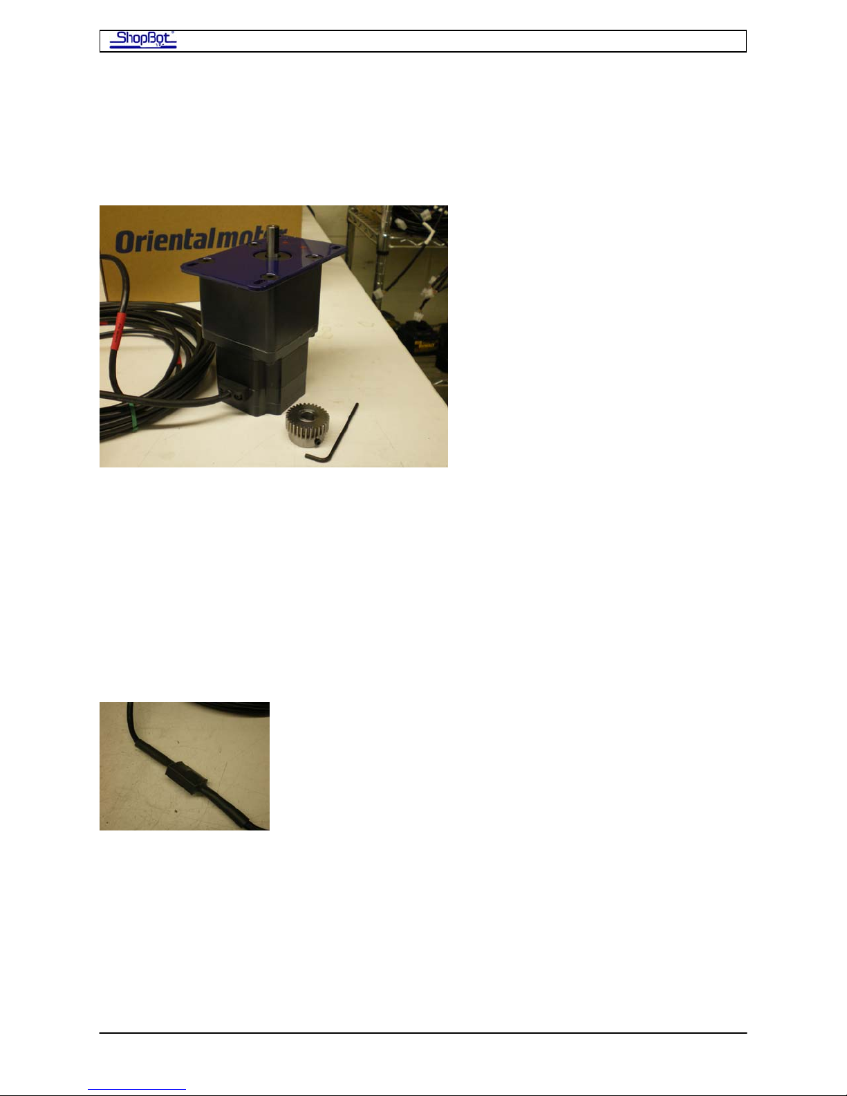
Locate the X and Y motors. These motors will already be fitted to a blue mounting bracket
and have a long cable attached. Also find the bag with your pinion gears.
• Fit a pinion gear on each of the motors and set the end of the gear flush with the
motor shaft. Don’t tighten the set screw yet; we’ll test fit the motors on the tool first.
• Note that the motor cables are color-coded to indicate the axis of the motor.
RED is X axis (there is an X-1 and an X-2 motor).
BLUE is the Y axis.
WHITE is the Z axis.
YELLOW is an accessory axis.
DO NOT REMOVE THE HEAT SHRINK THAT ENCASES THE CONNECTION BETWEEN
THE MOTOR AND CABLES. IT IS THERE TO INSURE SOLID CONNECTIONS IN ALL
CONDITIONS.
PRSAssembly080922.doc Copyright 2007,2008 ShopBot Tools, Inc
Page 31
ShopBot PRS Assembly Manual Page -31
Mount the Motors
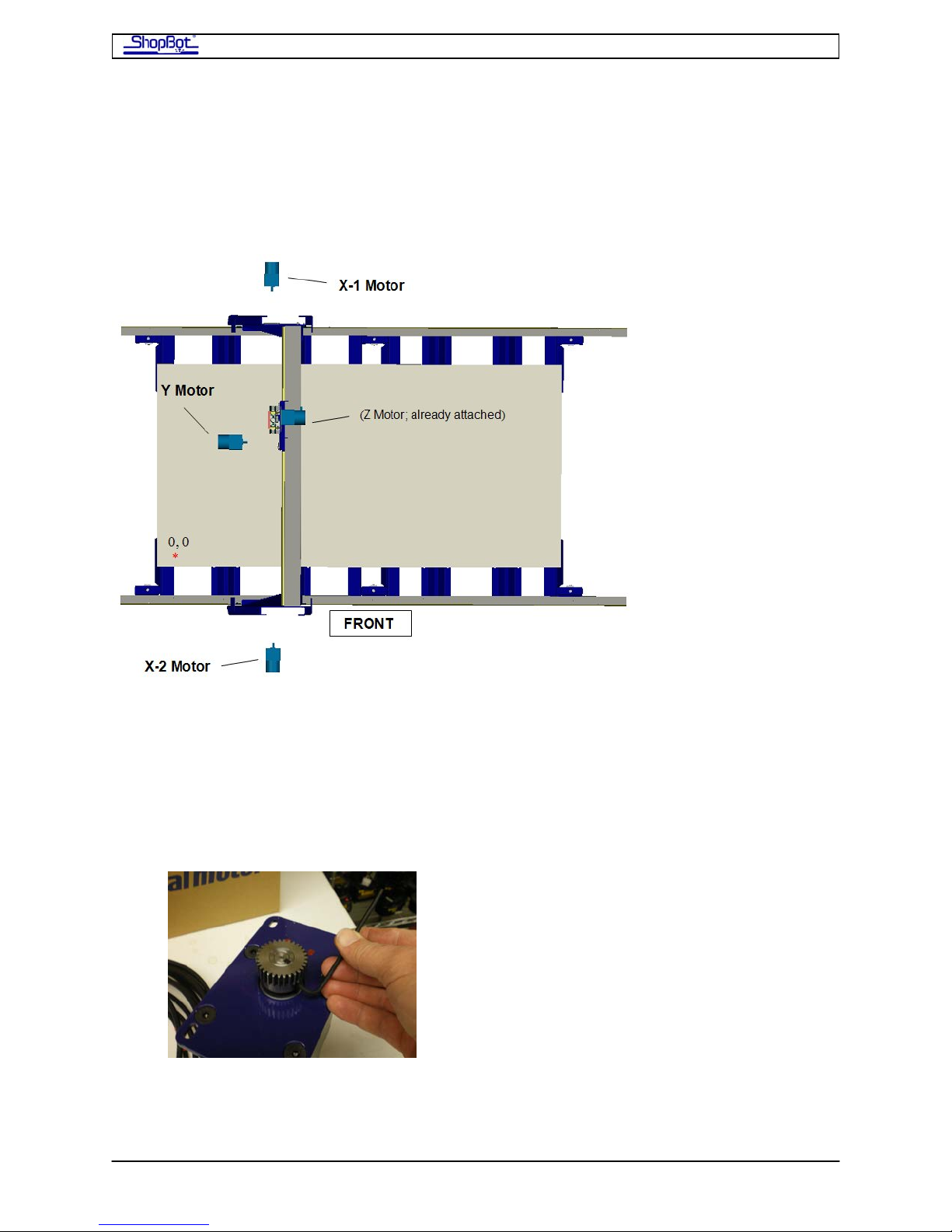
Since the motor cables (of correct lengths and motor direction orientation) have already
been attached to the motors, it is important that the motors and brackets be mounted in
the correct location. The mounting hardware for each motor (4 bolts) is already fitted to the
tool in the locations where the motors will be mounted.
• Make sure that you’ve got the right motor for the right location, then attach the
motor with two bolts and check to make sure the pinion is aligned on the shaft with
the rack.
• After checking the pinion alignment, remove the motor. Adjust the pinion location on
the motor shaft if necessary. Then tighten the two set screws. These set screws
have an embedded locking compound. Make sure you get them seated
tightly at this point.
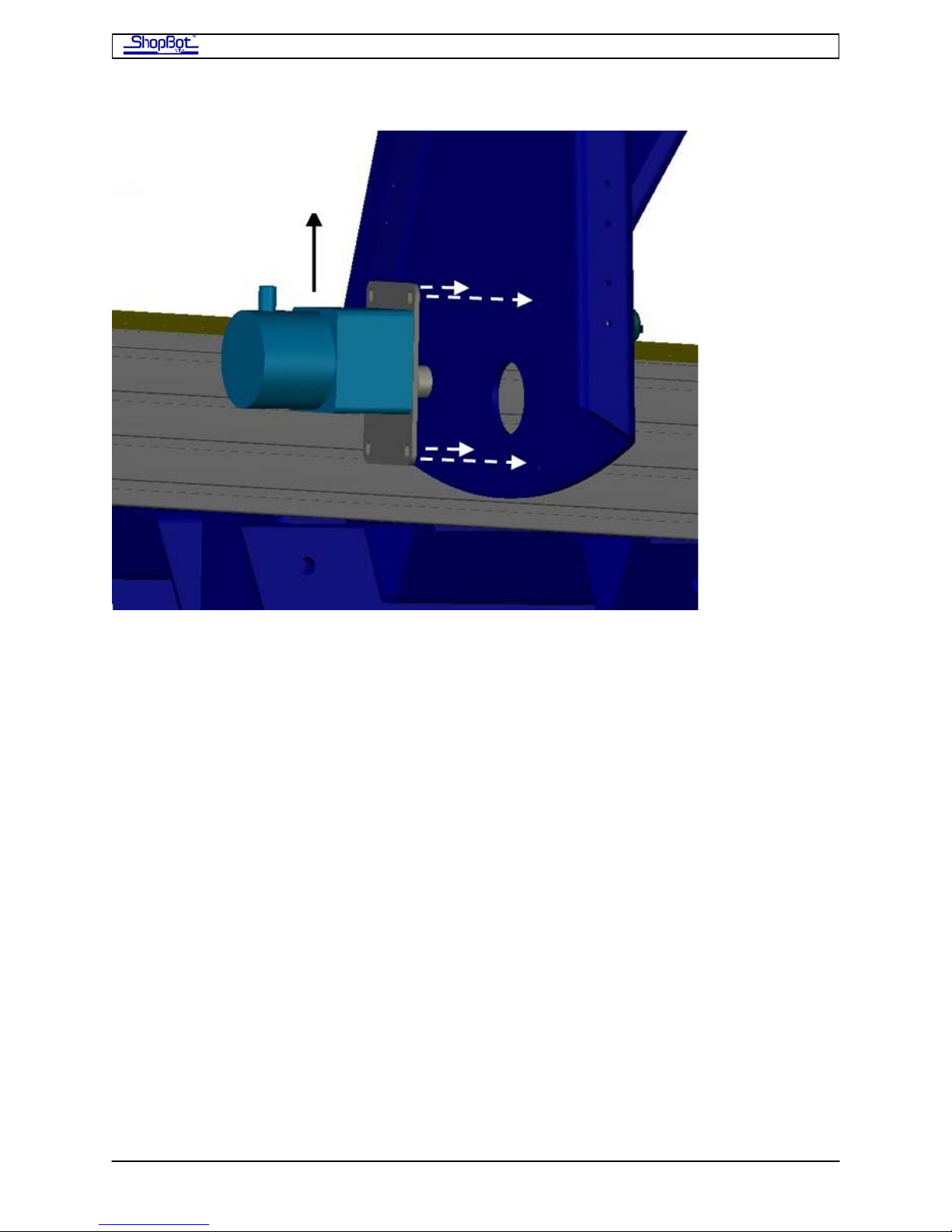
• With the pinion now fully tightened, mount the motor with all 4 bolts. Note that the
brackets are slotted. Slide the motor up so that the pinion is tightly engaged into the
rack.
PRSAssembly080922.doc Copyright 2007,2008 ShopBot Tools, Inc
Page 32
ShopBot PRS Assembly Manual Page -32
We recommend applying grease to the rack and pinions. A good quality bearing, lithium, or
Teflon grease will work well. The grease will keep the rack motion smooth and reduce gear
wear. (Surprisingly little debris actually collects in the grease.) Apply it by squeezing a little
into the rack every few inches. Moving the tool around will spread the grease and you can
wipe off any excess. It’s OK to push the cars around, but do not plug them in to the
Control Box yet.
PRSAssembly080922.doc Copyright 2007,2008 ShopBot Tools, Inc
Page 33
ShopBot PRS Assembly Manual Page -33
Set the Mechanical End Stops for the X Axis
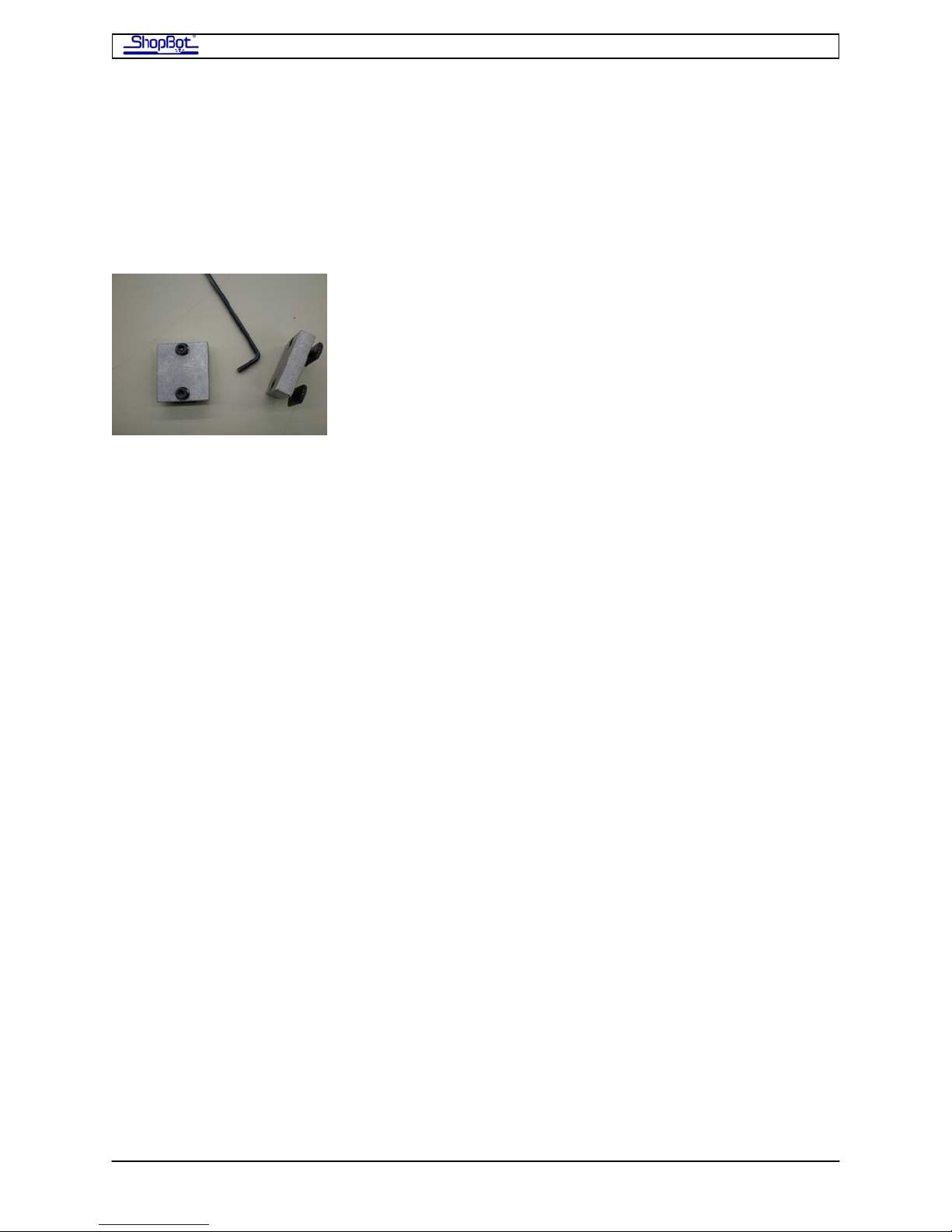
The Mechanical End Stops are aluminum blocks that limit the movement of the car on the
axis by stopping the pinion motion for the X-axis (The Y stops are already positioned). The
blocks are locked into the slotted track just under the gear rack by two set screws. You will
position one the end of each rail. So you will put 4 on the X-Rails - one on each end of each
rail.
• Take a moment to be sure that both X- and Y- Cars are moving up and down the
rails smoothly. The motors will create some resistance, but the motion should be
smooth and even with all wheel bearings riding on the rails and pinions fully
engaged.
• Lay out the 4 mechanical stops, one at each end of the rack on the X-Rails. Check to
make sure that the stops slide firmly into place over the ½” rack.
• Use the ⅛” Allen wrench, supplied with the pinion gear pack, to tighten on the
blocks.
• Carefully roll the X-Car to one end of the X-Rails, watching the inside of the X-Rail.
Roll the car until the wheels are resting within ¼” of the end of the X-rails. Put a
clamp on the rail to hold the car in place at that position.
PRSAssembly080922.doc Copyright 2007,2008 ShopBot Tools, Inc
Page 34
ShopBot PRS Assembly Manual Page -34
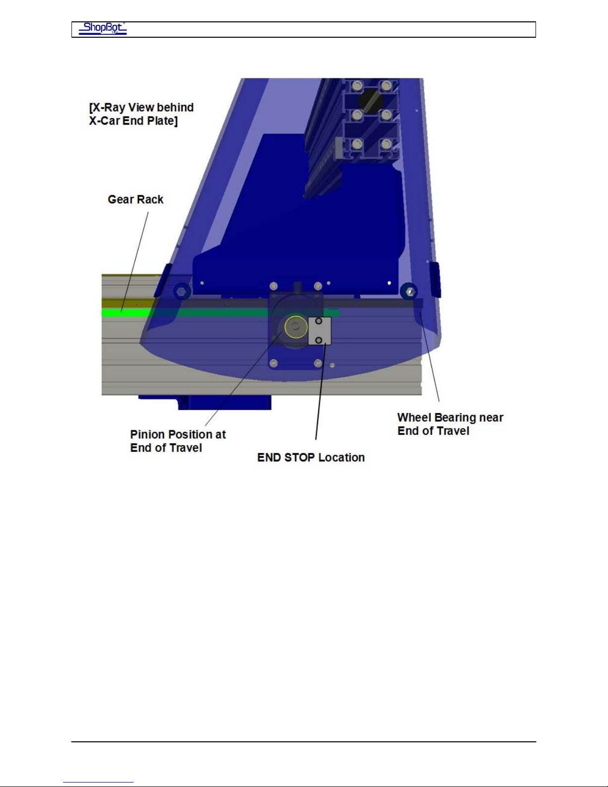
• Slide the Mechanical Stops into the track and up against the pinion on each rail. Then
push the car back.
• Tighten the stops in position.
• Move the X-Car to the other end of the table and set the other stops.
• When you later fine tune the square of your tool, you may do a final adjustment of
the position of the X-Car end stops. See section on Squaring.
Run the X-2 Motor Cable through the Aluminum Beam
The X-2 cable from the motor on the front side of your ShopBot runs through the X-Car
aluminum beam to the back side of your ShopBot before going to the Control Box.
• Run it through now by starting the connector through and then feeding the rest of
the cable.
PRSAssembly080922.doc Copyright 2007,2008 ShopBot Tools, Inc
Page 35
ShopBot PRS Assembly Manual Page -35
Mounting the Router or Spindle
Since the power requirements are different for a Porter Cable router than for a Spindle, we
install different components in the Control Box depending on which cutter you specified at
the time you placed your order. They are not interchangeable. Before retro-fitting your tool
from a router to a spindle or vice-versa, please call ShopBot to discuss the changes you will
need to make to reconfigure your tool.
If You Have a Porter Cable Router
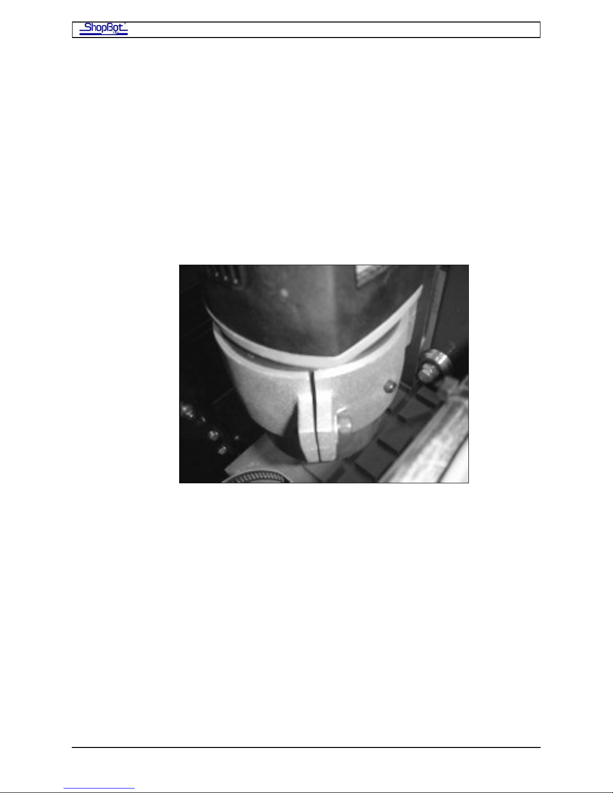
The Porter Cable fits into the aluminum sleeve that is already attached to the Z-axis.
• Remove the plastic insert from the router mount.
• Slide the router barrel into the plastic insert and then into the aluminum sleeve. Note
that there is a hole in the plastic insert for so that the grounding screw can be
tightened into electrical contact with the router shell. Line this up when you are
inserting the router into the mounting sleeve.
• Tighten the router into the bracket with an Allen wrench. Then tighten the grounding
screw “hand-tight”.
PRSAssembly080922.doc Copyright 2007,2008 ShopBot Tools, Inc
Page 36
ShopBot PRS Assembly Manual Page -36
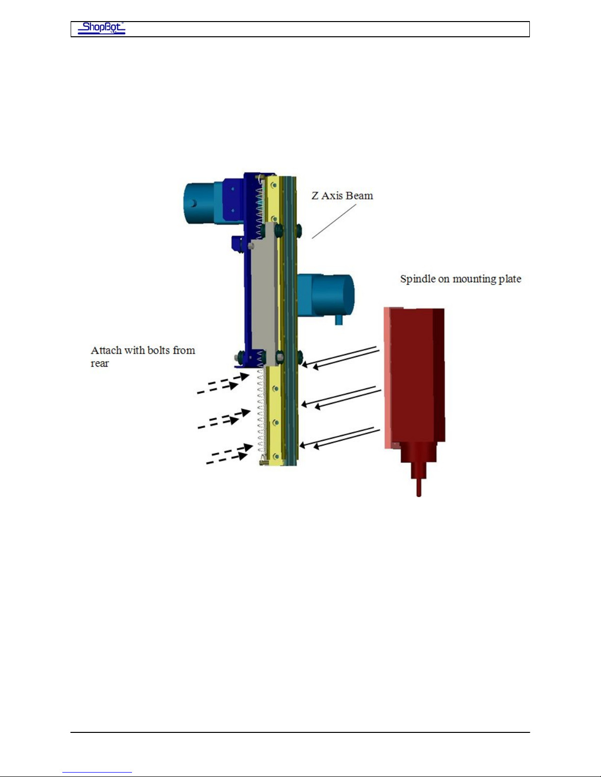
If You Have a High Frequency Spindle:
The spindle will come fitted with a custom aluminum backing plate. This plate attaches to
the pre-drilled holes at the bottom of the Z axis using 6, 5/16” socket-head bolts. These
bolts pass through the beam and into the plate. As they are tightened, they will seat at the
bottom of the groove in the slot..
• Pull the Z axis beam down to expose the back of the 6 bolt holes. Clamp it in position
so it does not pull back up while you are working on it. Hold the spindle to the beam
and start the 6 bolts into the plate. Note that these bolts have no washers.
• Pull the plate up evenly by tightening all the bolts gradually. Then do a final
tightening of all the bolts.
• To mount the spindle, move the gantry up to the far end of the table. Pull the Z axis
beam down to expose the back of the 6 bolt holes. Clamp it in position so it does not
pull back up while you are working on it. Hold the spindle to the beam and start the
6 bolts into the plate. Note that these bolts have no washers.
PRSAssembly080922.doc Copyright 2007,2008 ShopBot Tools, Inc
Page 37
ShopBot PRS Assembly Manual Page -37
After Mounting the Router/Spindle
Now you will run the wire for motors and accessories and do a little tidying up, then you’ll
be ready to plug in your tool, test it out, and put it to use. We will use a lot of wire-ties in
this step, so in addition to your other tools, get the wire-tie bag handy and a set of nippers
to trim them with. If you have never done it before, note that if you need to cover a long
distance with ties, you can piggy-back 2 or 3 of them together to create a larger loop.
Wheel Guards
The guard plates are universal and come in a package of 7; others will be used below. You’ll
find all the hardware in a packet
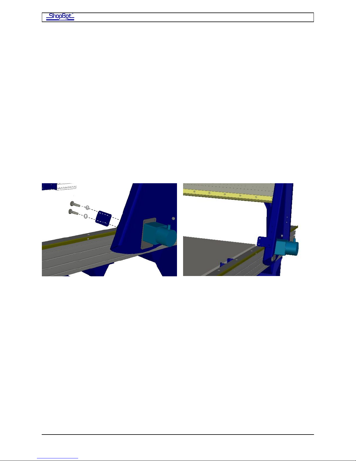
Put all 4 of the Wheel Guard plates on now. Mount a Wheel Guard on the leading and
trailing edges of each X-Car End Plate outside each of the 4 Wheel Bearings. Attach to the
End Plates using two, ¼” socket-head bolts and lock washers.
PRSAssembly080922.doc Copyright 2007,2008 ShopBot Tools, Inc
Page 38
ShopBot PRS Assembly Manual Page -38
Proximity Switches
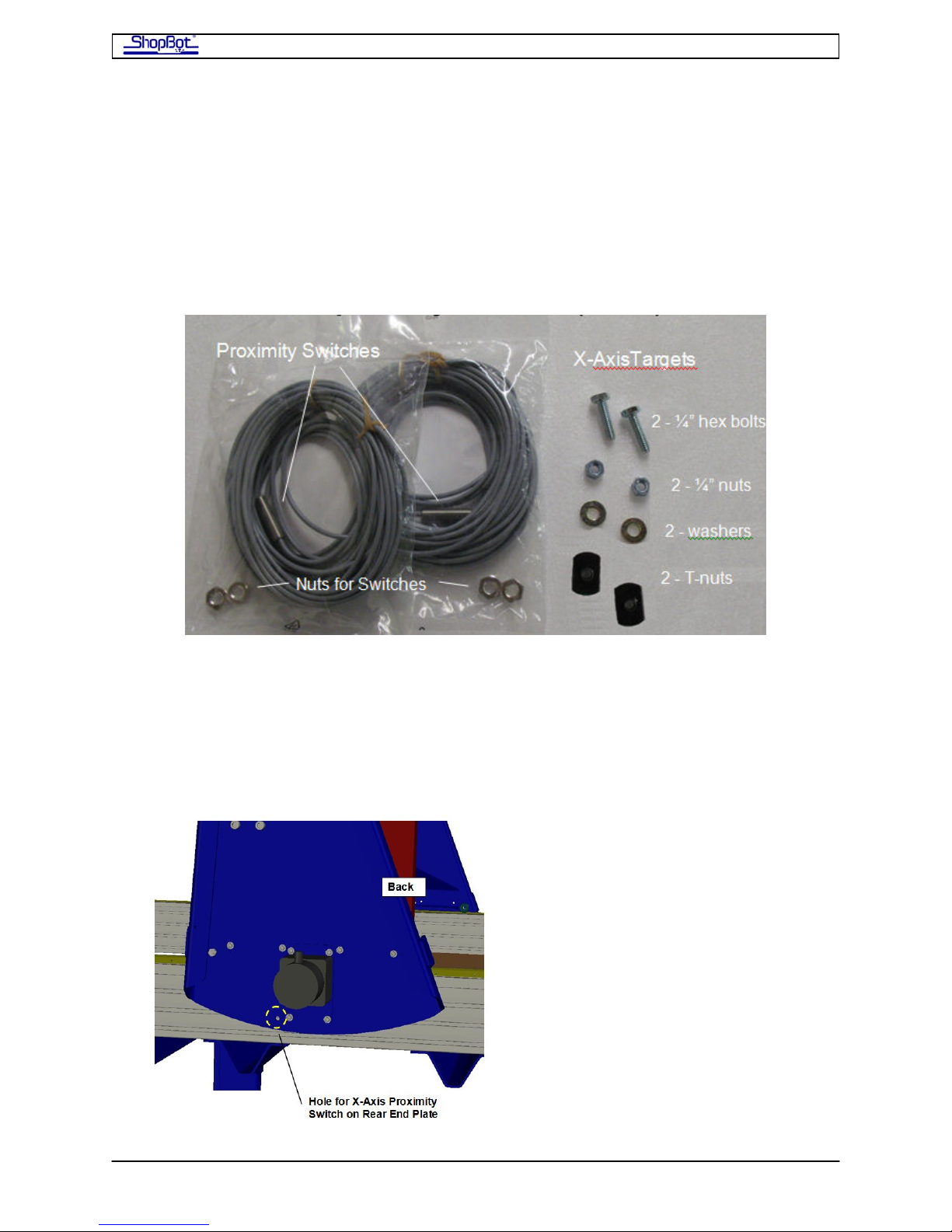
You’ll find the Proximity/Limit Switches, targets and mounting hardware bagged together.
These switches are used to set the zero location for the X- and Y-axes, and also serve to
signal the end of the axis to the tool and limit its motion. They switches look like a piece of
threaded rod with a wire exiting from one side. Mount these sensors on the YZ-Car and on
the back of the X-Car.
Install the Proximity Switches
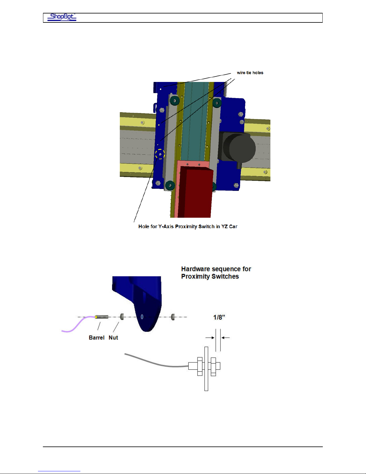
• Attach the switches as indicated, with a nut holding them on each side of the plate.
The switches should protrude about 1/8” from the inside of the car.
• Mount one Proximity Switch (for the X-axis) through a hole in the bottom of the rear
End Plate on the X Car.
PRSAssembly080922.doc Copyright 2007,2008 ShopBot Tools, Inc
Page 39
ShopBot PRS Assembly Manual Page -39
• Mount the second Proximity Switch (for the Y Axis) through a hole on the left side of
the YZ-Car.
•
•
Y-axis Targets
Look at the front side of the Y-Axis Beam on the X Car. You will see t two bolt heads
sticking up in the grooves between the two rails. These are the targets for the proximity
switches (the switches work by electrical induction).
PRSAssembly080922.doc Copyright 2007,2008 ShopBot Tools, Inc
Page 40
ShopBot PRS Assembly Manual Page -40
• Push the Proximity Switch over these targets and check the spacing. You want about
a 2mm gap (.08”) between the target and the Proximity Switch. After you get your
tool connected, you can check and adjust these targets.
X-Axis Targets.
In your hardware pack, you will find hardware for 2 additional targets. After you get the
tool running, you will set these at the appropriate location and set the switch to the
height to just clear the target. See Test Spin???
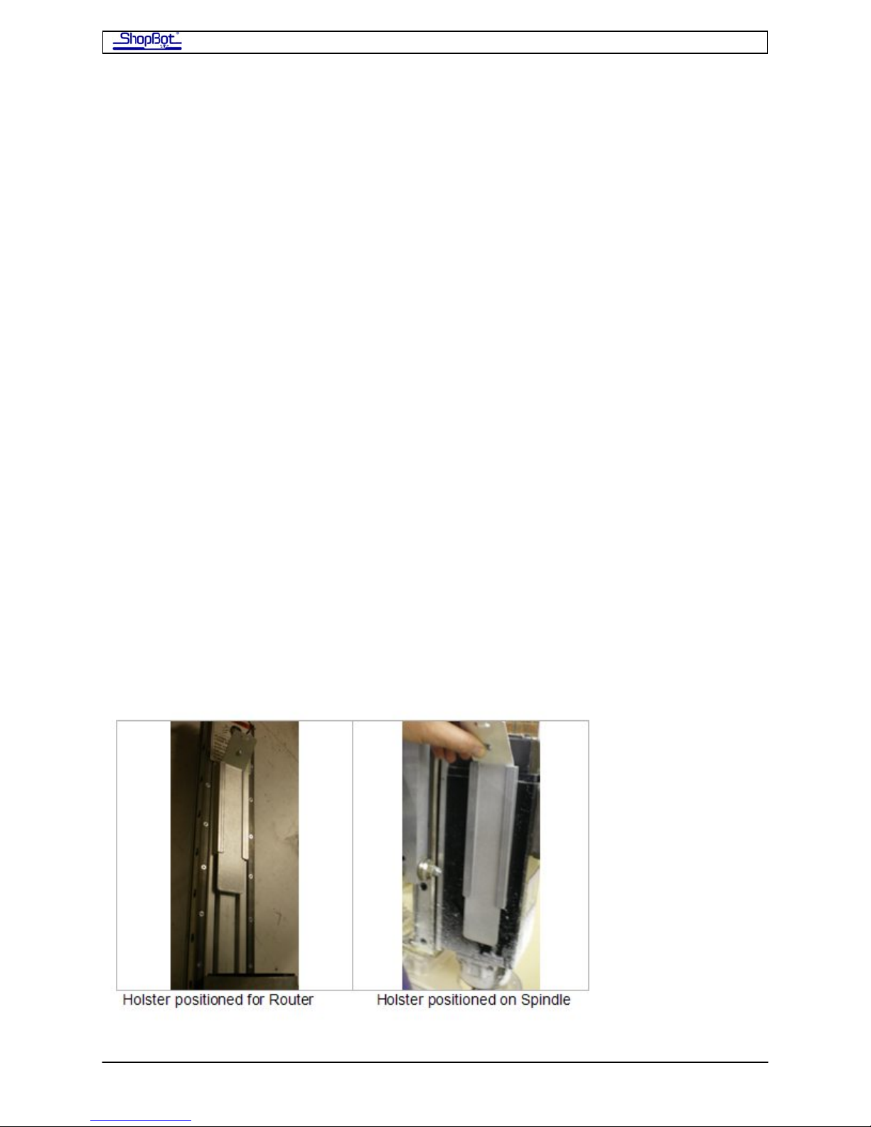
Z-Zero Plate Holster
The Z-Zero plate is a narrow stick of aluminum that is used to set the zero position of the Zaxis of your tool. This can be set to the height of the material you are working with or to
your table surface and is typically done. after you have changed cutters or materials. You’ll
find it with its cable in a bag in your shipping crate.
Mount the Z-Zero Plate Holster anywhere that is convenient for you, either on or off the
tool. Here we’ll describe how to ‘holster’ it on the tool, near where you will need it. The
holster is made of two pieces of aluminum channel that capture the Z-Zero Plate from the
side. We find the best location in our use to be in the middle of the Z axis beam if you are
using a router, or on the side of the spindle if using a spindle.
You can go ahead and install the holster brackets now so that you can run the wire along
with other cabling, or you can wait until you’ve used the tool for a while to decide if you
want the Z-Zero plate on the tool, or at your work station.
The channel pieces have adhesive on the back that is used to mount them. Mount them so
they will just capture the plate as it slides in and jam tight at the bend at the top. The
adhesive also electrically isolates the plate when not in use.
Note that the cabling for the Z-Zero plate also has a connector that can be used to connect
the optional digitizing probe.
PRSAssembly080922.doc Copyright 2007,2008 ShopBot Tools, Inc
Page 41
ShopBot PRS Assembly Manual Page -41
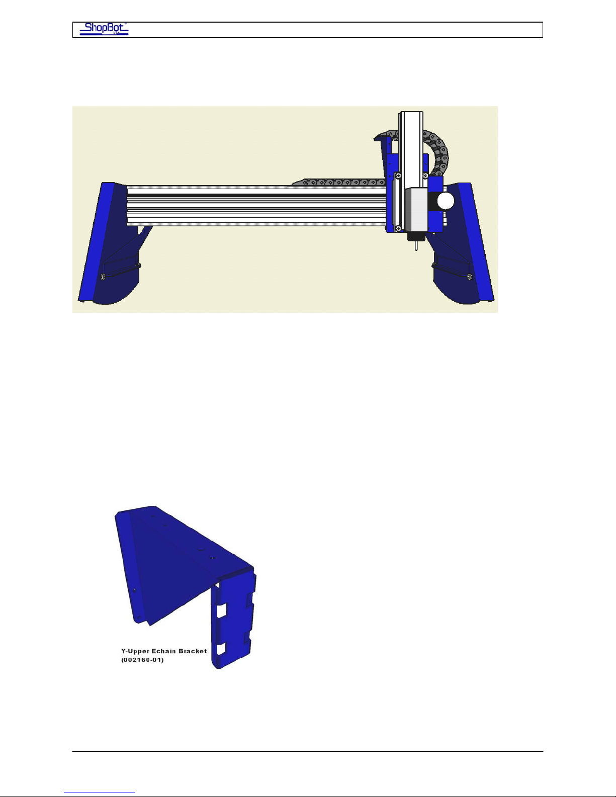
PRS Y-axis EChain Installation
Doc#330
This document shows how to install the Energy chain (Echain) on the Y-axis on ShopBot PRS
and PRS BT models. Note that the dust collection hose from the ShopBot Dust Skirt must be
routed overhead when an Echain is installed; the Y-upper Echain bracket has a fixed
attachment point for the dust collection hose.
The Y-axis Echain Components
The Y-axis Echain has three main components and a few specialized pieces of hardware.
The Y-upper Echain bracket (002160-01)
mounts to the back of the YZ-car and carries
the Echain. Hose clamps in the slots of the
tab support the dust hose. This bracket is
mounted on either the left (PRS) or the
right (PRS BT) of the YZ-car if you are
looking at the spindle head on.
PRSAssembly080922.doc Copyright 2007,2008 ShopBot Tools, Inc
Page 42
ShopBot PRS Assembly Manual Page -42
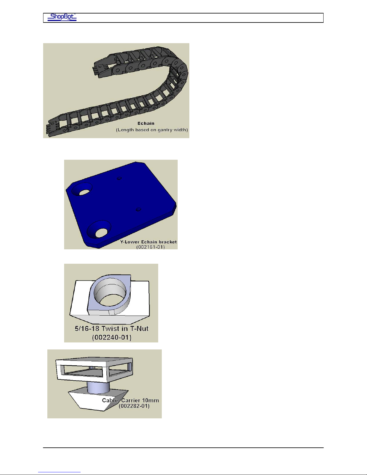
The Echain comes in the length to match
the width of the Y-axis of the ShopBot
ordered. These Echains are center
mounted so the Echain itself will not
physically extend from the end plate to
the Y-upper Echain bracket.
The Y-lower Echain bracket (002161-01)
mounts to the top of the Y-beam extrusion
and holds the Echain at a fixed location near
the center of the gantry. Location of this
bracket differs on various width ShopBots. A
chart is included later in the instructions..
One of the specialized pieces of mounting
hardware is the 5/16-18 Twist in T-Nut
(002240-01). Two of these are used to
mount the Y-lower Echain bracket to the Ybeam extrusion. They slide into the slot of
the extrusion and turn 90˚ when tightened.
Other hardware used to mount these will be called out through out this document when
needed.
PRSAssembly080922.doc Copyright 2007,2008 ShopBot Tools, Inc
The last piece of specialized hardware is the
cable carrier (002282-01). These slip inside
the slot of the Y-beam extrusion and turn
90˚ to help with wire management for
cables going through the Echain. Zip ties are
used in combination with these to achieve
this.
Page 43
ShopBot PRS Assembly Manual Page -43
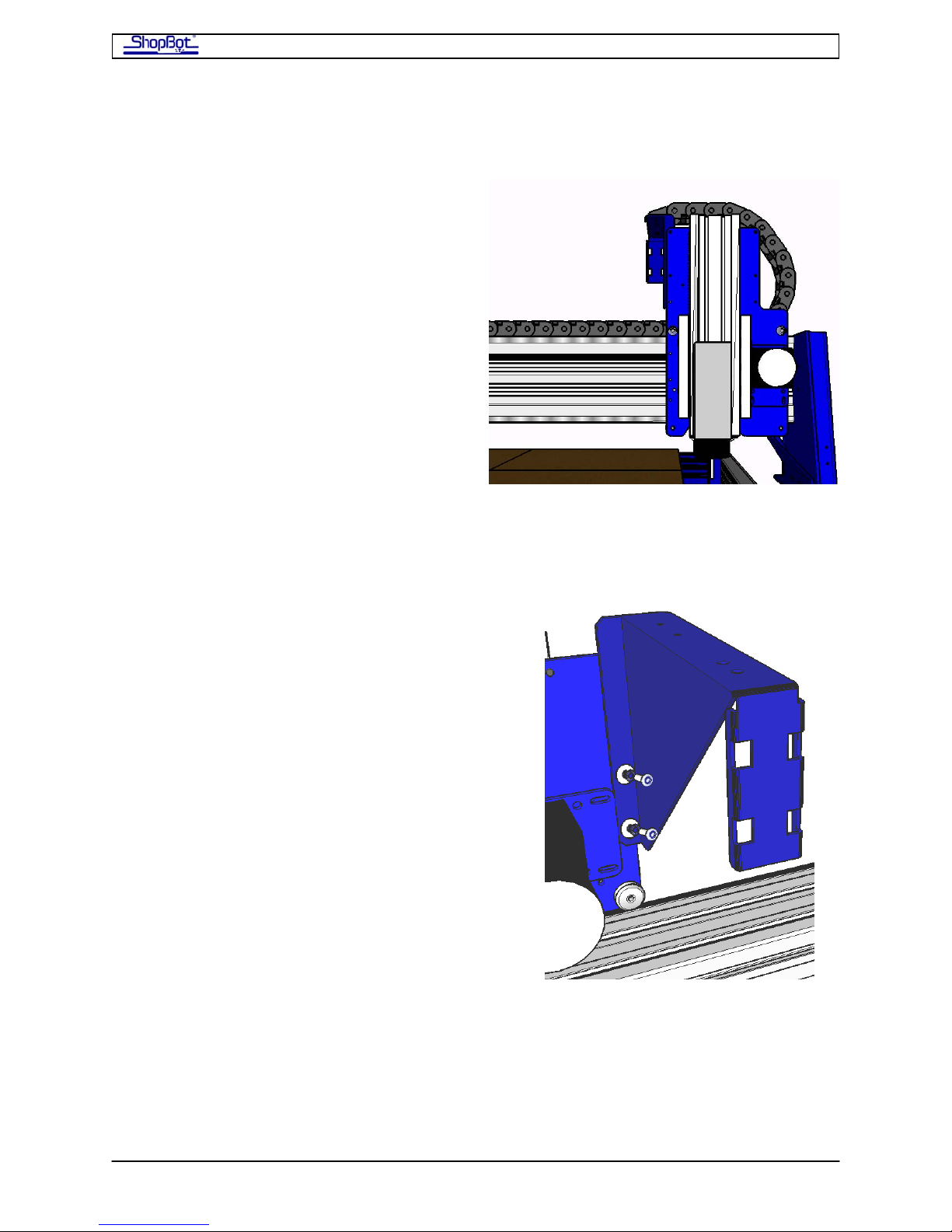
Mounting the Y-axis Echain on the PRS
Remove any previously-installed wire guide
and wire guide brackets from the gantry and
YZ-car if necessary. When the YZ-car is
viewed head on, the Y-upper Echain bracket
will be located on the back left side of the YZ
car and the Echain will loop to send the
cables toward the back of the ShopBot.
Step 1: Installing the Y-upper Echain bracket.
• (1) Y-upper Echain bracket (002160-01)
• (2) ¼-20 x 1/2 socket head screws
• (2) ¼” lock washers
• (2) ¼” flat washers
On the back left side edge of the YZ-car there
are 2 ¼-20 holes. Align the holes in the longest
tab of the Y-upper Echain bracket with the
tapped holes of the YZ car. Using the ¼-20
screws, lock washers, and flat washers, secure
the bracket tightly to the YZ car.
PRSAssembly080922.doc Copyright 2007,2008 ShopBot Tools, Inc
Page 44
ShopBot PRS Assembly Manual Page -44
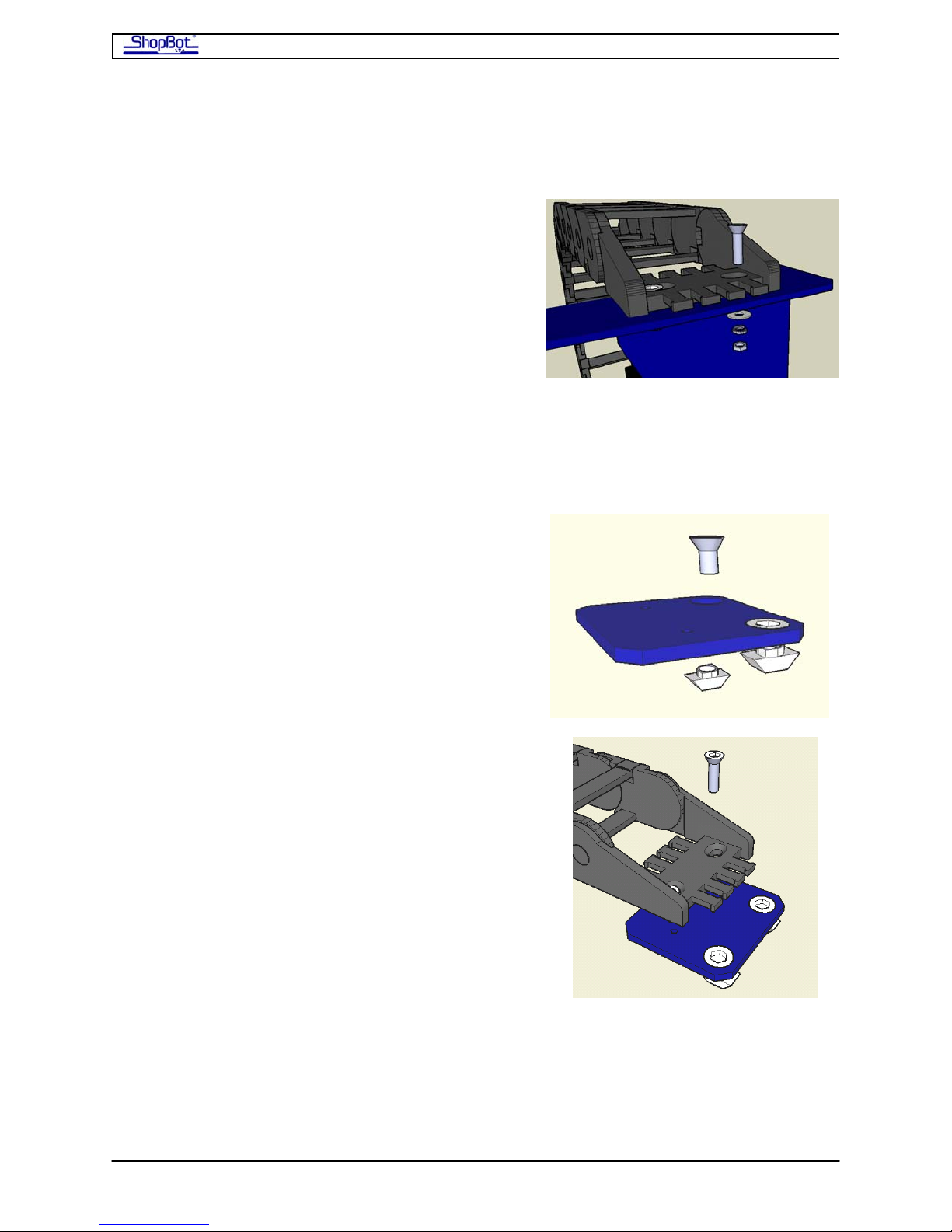
Step 2: Mounting the Echain to Y-upper bracket
• (1) Echain
• (2) 10-32 flat head screws
• (2) #10 flat washers
• (2) #10 lock washers
• (2) 10-32 hex nuts
Position the Echain so that it loops towards the right
when you are facing the front of the YZ car. Align
the counter sunk holes in the Echain with the holes
in the top tab of the Y-upper bracket. Use the
screws, flat washers, lock washers, and hex nut to
tighten the Echain to the Y-upper bracket.
Step 3: Mounting the Y-lower Echain bracket
• (1) Y-lower Echain bracket (002161-01)
• (2) 5/16-18 Twist in T-Nut (002240-01)
• (2) 5/16-18 x 5/8 flat head screws
• (2) 10-32 x ¾ flat head screws
Place the 5/16 flat head screws into the Y-lower
Echain bracket. Start a few of the threads of the
twist in T-nut onto the screws.
Align the counter sunk holes in the Echain with the
holes in the top of the Y-lower bracket. Loosely
start the 10-32 x ¾ screws into the Y-lower Echain
bracket. Position the Y-lower bracket the correct
distance from the back side end plate on the PRS
ShopBot from the chart below.
Note: Distances are measured from the edge
closest to the counter sunk holes of the Ylower bracket to the inside edge of the back
side end plate.
Tighten the 5/16-18 flat heads and Twist in T-nuts
into the slots of the gantry extrusion and then
tighten the 10-32 screws fully.
PRSAssembly080922.doc Copyright 2007,2008 ShopBot Tools, Inc
Page 45
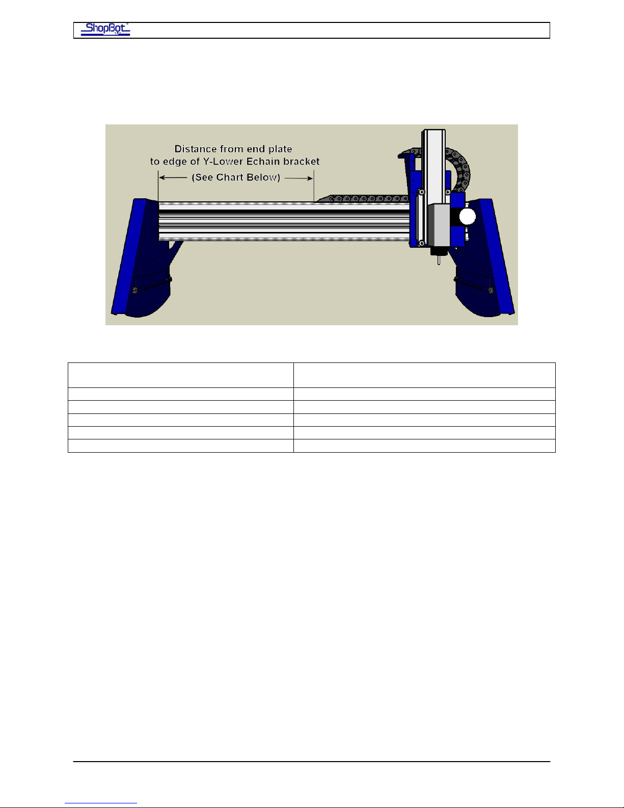
ShopBot PRS Assembly Manual Page -45
Chart showing distance from End Plate to edge of Y-Lower Bracket
Cutting width in Y-axis
(Beam length)
32in (47.992in or 1219mm) 22.50in (572mm)
48in (66.338in or 1685mm) 31.50in (800mm)
60in (78.346in or 1990mm) 37.50in (953mm)
72in (90.354in or 2295mm) 43.50in (1105mm)
108in (126.456 or 3212mm) 61.50in (1562mm)
After the Echain is installed, move the Y-axis back and forth the full extent of travel. The
Echain should at no time feel as though it is binding or under tension. If this appears to be
the case, loosen the 5/16-18 flat heads and adjust the Y-lower bracket slightly.
Distance between end plate and Y-lower
bracket
PRSAssembly080922.doc Copyright 2007,2008 ShopBot Tools, Inc
Page 46
ShopBot PRS Assembly Manual Page -46
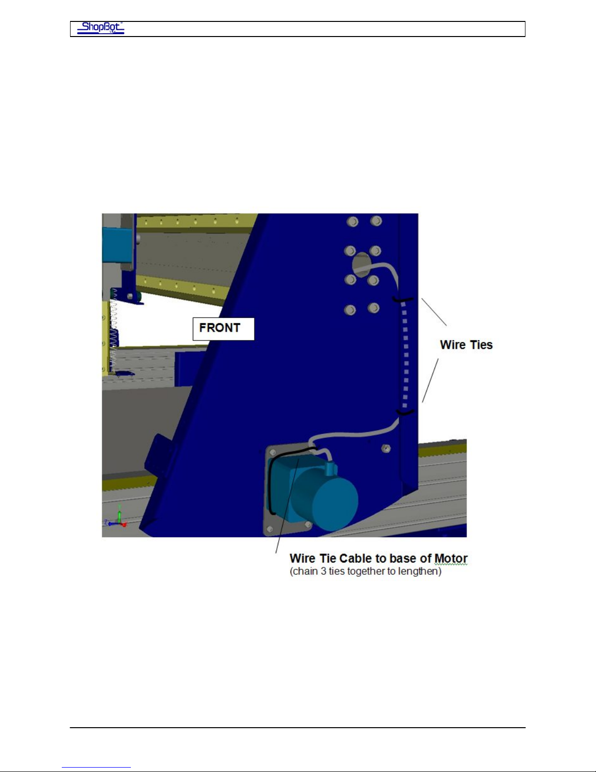
Secure cables and wiring
Use a chained wire tie (link 3 standard wire ties together) and secure the X-2 Motor
Cable to the base of the X-2 Motor.
Run the cable to the back side of the front End Plate, and secure it with two wire ties
behind the back lip of the plate.
PRSAssembly080922.doc Copyright 2007,2008 ShopBot Tools, Inc
Page 47
ShopBot PRS Assembly Manual Page -47
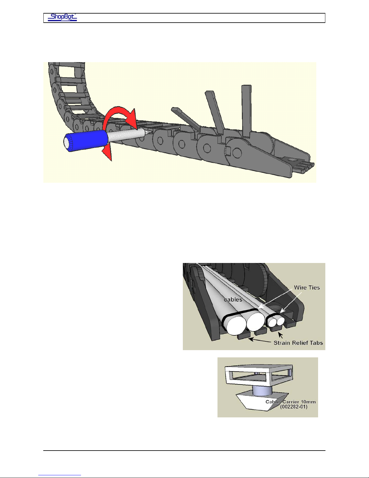
Opening the Echain
Move the YZ-car to the far end of the Y-axis so that the motor is not over the Echain. This
keeps the motor from interfering with the hinged access bars. With a flat head screw
driver, insert the tip into either side of the hinged access bar. Turn the screw driver
approximately ¼ turn clockwise and then ¼ counterclockwise or until the sides of the
access bars release. Open the access bars to run all wiring that is common to the YZ-car,
spindles, or air drills.
Caution: Do to the low clearance of the Z motor in relation to the Echain. DO NOT
attempt to move the YZ-car while the hinged access bars are in the open position.
Doing so will result in the snapping off of these access bars.
Use wire ties in addition with the strain
relief tabs on the ends of the Echain to help
with the strain relief of the cables. DO
NOT use wire ties inside the Echain.
This could result in added strain on the
cables.
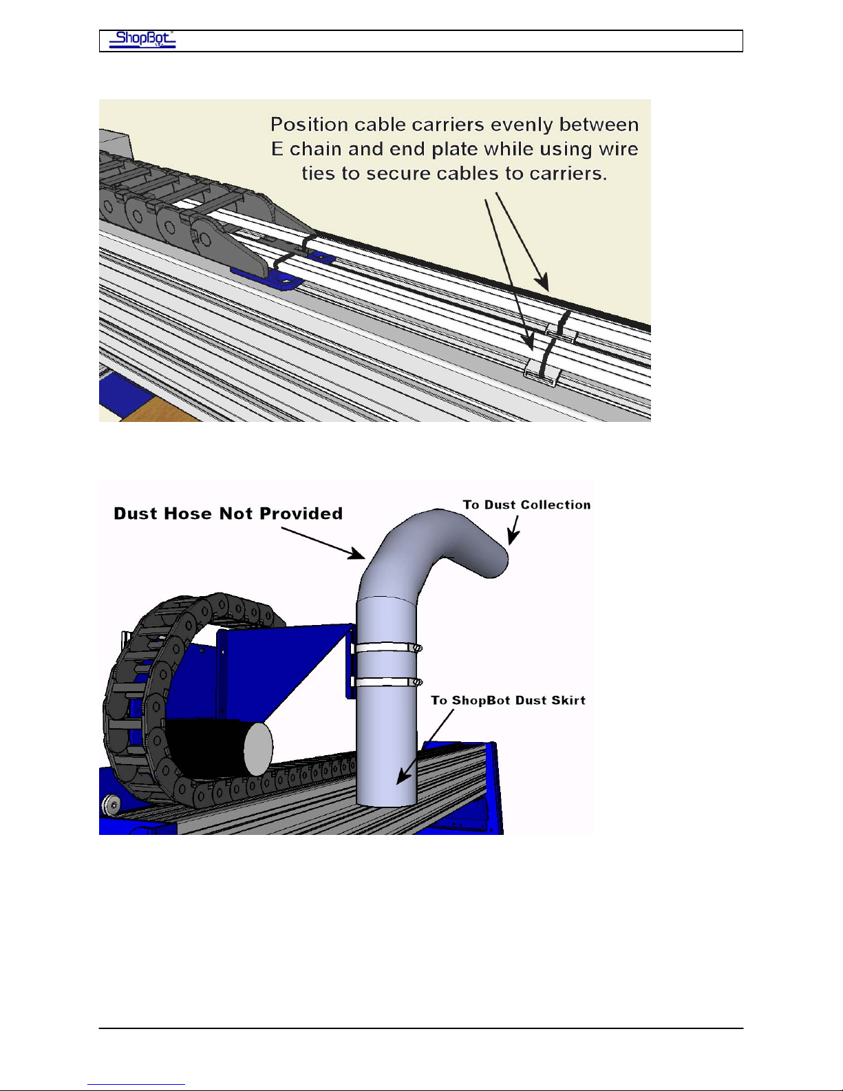
Place the cable carriers on the top side of the
gantry extrusion. Evenly space these between the
Y-lower bracket and the end plate inside the 2 slots
in the extrusion. Place the lower end into the slot
and turn 90˚ to lock the cable carrier in place. Use
wire ties to secure cables along the length of the
gantry and off the back of the machine.
PRSAssembly080922.doc Copyright 2007,2008 ShopBot Tools, Inc
Page 48
ShopBot PRS Assembly Manual Page -48
Connecting Overhead Dust Collection
The Y-upper Echain bracket has a tab that comes with two hose clamps to hold a 4”
overhead dust collection hose. Neither the hose nor the dust collection system is provided
by ShopBot. Extend the length of the overhead dust hose to the ShopBot dust skirt and
connect the dust skirt. For more information about the installation and use of the dust skirt,
please see Installing the PRS Dust Skirt (SBG00326DustSkirtPRS). Make sure that there
is enough hose to accommodate the lowest position of the Z axis, then secure the hose to
the Y-upper Echain bracket with the provided hose clamps.
PRSAssembly080922.doc Copyright 2007,2008 ShopBot Tools, Inc
Page 49

ShopBot PRS Assembly Manual Page -49
Run the YZ Wiring
You’ll run the wiring from the YZ motors, router/spindle, proximity switch, and Z-Zero plate
(if mounted) from the YZ Car, through the Echain. You will tie the router/spindle cable on
the left side of center, and the motor and accessory wires to the right side of center. You
want to keep the electrically-noisy router/spindle wires as separate as possible from the
other wires.
As you are first laying the wires out, only tighten the wire ties in a loose loop. After you are
sure everything is in the right place you can draw the ties tight and trim them. Later, you
can also attach your dust collector hose.
• Now run the router/spindle wire directly from the router/spindle using a large loop
and attaching it at the second wire-tie, The loop from the router/spindle should allow
the router/spindle full motion without the wire being in danger of chaffing on the Z
beam or YZ Car.
• Before running the motor wires, secure them first as they exit the motor, close to
the base of the motor using a long wire-tie (3 linked together).
• Note that for the Proximity Switch, there are two holes for securing the wire up to
the wire guide. Make sure this wire can’t get under the wheel bearing.
Neaten up the Wiring at the Back Side of the X Car
Wire-tie the X-1 Motor Cable to the base of the motor with a lengthened wire tie.
Secure all the cables coming from the Echain (except the router/spindle cable), along with
the X-1 Motor Cable, behind the rear lip of the Back End Plate using 2 wire ties.
Create a Cable Loop on the way to the Control Box
• From the point where the cables leave the back of the X Car, you can tie the motor
and accessory cables into a single bundle with a wire every foot or so.
• But don’t bundle the router/spindle cable with the other wiring. You will run the
Router/Spindle cable over basically the same route as the Motor Cables. But avoid
having it any closer or more parallel than necessary by letting it hang slightly
differently, etc.
• Use the remaining 3 universal Bracket Plates to attach the wiring to the bottom of
the table. Use 5/8” ¼” bolts and Tee-nuts in the bottom groove and then wire-tie
through the holes in the plate below.
• Create a large loop in both the Motor Wire Bundle and the router/spindle cable as it
exits the X gantry. This loop should be just long enough that the car is able to transit
from one end to the other of the tool without straining the cable.
You’ve now completed assembly of your PRS CNC Tool and are ready to connect it to the
Control Box and try it out. The instructions for hooking up to your Control Box are different
for PRSalpha and PRSstandard tools. Make sure to use the correct section that describes the
connection process for your specific tool.
PRSAssembly080922.doc Copyright 2007,2008 ShopBot Tools, Inc
Page 50
ShopBot PRS Assembly Manual Page -50
Hooking Up to the Control Box
Do’s and Don’ts
DO contract with a licensed electrician experienced with industrial equipment to
wire the power to the PRSalpha control box, a spindle/VFD and for a displacement
or regenerative vacuum blower system for hold-down. Documentation provided with
spindles and blowers details their power requirements.
DON’T plug in or unplug motors or motor cables when the control box is on.
DON’T disconnect the motor, or the motor cable at the junction in the Control Box,
without first turning off and unplugging the control box. The Control Box for your
new ShopBot contains integrated circuit components for driving your stepper motors
('drivers' for short). These drivers are at the heart of the performance capabilities of your
tool. Each one has sophisticated logic circuitry for micro-stepping as well as current handling
paths that control and rapidly switch four output lines that each deliver up to 60 volts at 2
amps to the motors of your tool. Each chip programs the output to the coils of your stepper
motors, regulates the actual currents that flow on a micro-second basis, and moves your
stepper motors at up to several thousand steps per second. Despite their current handling
capabilities, these chips can be vulnerable to the large voltage spike that occurs if the drive
is disconnected under load.
DON’Tt push the tool manually with the motors plugged into the driver but powered off.
The motors will send currents back into the drivers. Use the software keypad control of your
ShopBot which gives you convenient, full-movement capability. If you need to move the tool
manually for a set-up or maintenance task, shut down and unplug the control box, then
disconnect the motors before pushing the carriages.
DO use instructions for either the PRSalpha or the PRSstandard – whichever one
you have.
PRSAssembly080922.doc Copyright 2007,2008 ShopBot Tools, Inc
Page 51

ShopBot PRS Assembly Manual Page -51
Hooking Up Your PRSalpha
Powering the PRSalpha Control Box
The power to the PRSalpha Control Box should be wired into a fused disconnect by a
licensed electrician familiar with industrial equipment.
The Power Requirements for the PRSalpha Control Box and Router/Spindle vary according to
your configuration. The table below outlines some of the power requirements for different
configurations. A schematic for the power requirements for your specific configuration can
be found in the door of the PRSalpha Control Box
Since the power requirements for a Porter Cable router and for a Spindle are different, we
install different components in the PRSalpha Control Box depending on which you will be
using. This is not user configurable. You specified which you would be using at the time you
placed the order.
ShopBot Configuration PRSalpha: US Standard, 60Hz
PRSalpha Control Box and Porter Cable Router
220V single phase, 25A circuit. The 2 legs will be split into two 110 circuits inside the
PRSalpha Control Box: one for the PRSalpha Control Box, and one for the router.
PRSalpha Control Box and Spindle (3 phase)
110V 25A circuit for the PRSalpha Control Box plus 230V 3-phase circuit for the spindle.
Specifications for full-load current of the different models of spindle are provided with the
spindle.
PRSalpha Control Box and Spindle (single phase)
110V 25A circuit for the PRSalpha Control Box plus 220V single phase circuit for the spindle.
Specifications for full-load current of the different models of spindle are provided with the
spindle.
PRSalpha Control Box and two Porter Cable routers
220V single phase, 30A circuit. The 2 legs will be split into two 110 circuits inside the
PRSalpha Control Box: one for the PRSalpha Control Box, and one for the two routers.
PRSalpha Control Box and two Spindles
110V 25A circuit for the PRSalpha Control Box plus the appropriate 220V or 230V circuit for
the spindles.
ShopBot Configuration PRSalpha: European Standard, 50Hz
PRSalpha Control Box and 230V/50Hz Porter Cable Rout er (single speed)
230V single phase line with 15A circuit for the PRSalpha Control Box plus 15A/230V single
phase line for the Porter Cable Router.
PRSalpha Control Box and Spindle (3-phase)
230 V single phase circuit (15A) for the PRSalpha Control Box plus 380V 3-phase circuit for
the Spindle. Specifications for full-load current of the different models of spindle are
provided with the spindle.
PRSAssembly080922.doc Copyright 2007,2008 ShopBot Tools, Inc
Page 52
ShopBot PRS Assembly Manual Page -52
Mount the PRSalpha Control Box
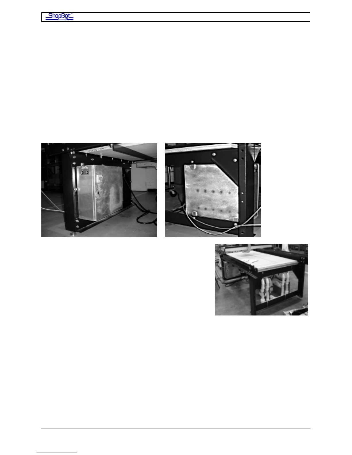
Mount the PRSalpha Control Box in a location so that the operator can reach the front of the
Box each time a file is run because it is necessary to hit the start button to engage the
safety contactors.
There are flanges at the top and bottom of the PRSalpha Control Box for mounting it. One
option is to attach it to your ShopBot near the Home position (Lower Left corner). Drill holes
through the table cross supports and gussets to mount the PRSalpha Control Box to the
Table. The PRSalpha Control Box can also be mounted on the wall near your tool as shown
in the accompanying image. Your PRSalpha Control Box may look different depending on
the model purchased.
If you mount the PRSalpha Control Box on the table and
you also have a vacuum hold-down system, mount the
shut-off valves for the vacuum system at the opposite
end of the table. Locate the vacuum pump itself and any
exhaust pipes away from the PRSalpha Control Box.
Vacuum shutoff valves mounted at opposite end of table
from PRSalpha Control Box
If you mount the PRSalpha Control Box to the wall, allow at least 1 1/2" of clearance
between the back of the PRSalpha Control Box and the wall to allow heat to dissipate from
the PRSalpha Control Box. Allow enough space above and below the box for air to circulate
around the PRSalpha Control Box. The PRSalpha Control Box enclosure acts as a heat
sink for the electronics.
PRSAssembly080922.doc Copyright 2007,2008 ShopBot Tools, Inc
Page 53
ShopBot PRS Assembly Manual Page -53
Explore the PRSalpha Control Box
After the electrician has hooked up your PRSalpha Control Box
and router or spindle, it’s time for you to get involved again. The
electrician is not expected to know how to hook-up the tool itself
to the PRSalpha Control Box. That process is covered in the
following instructions.
Disconnect electrical power to the PRSalpha Control Box.
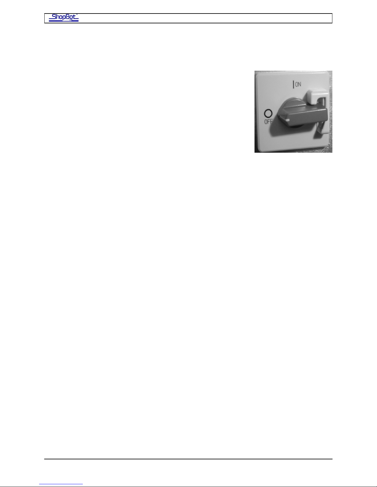
Open the side of the box with a screwdriver (quarter turn). Note
that the door cannot be opened or closed unless the switch is
turned off.
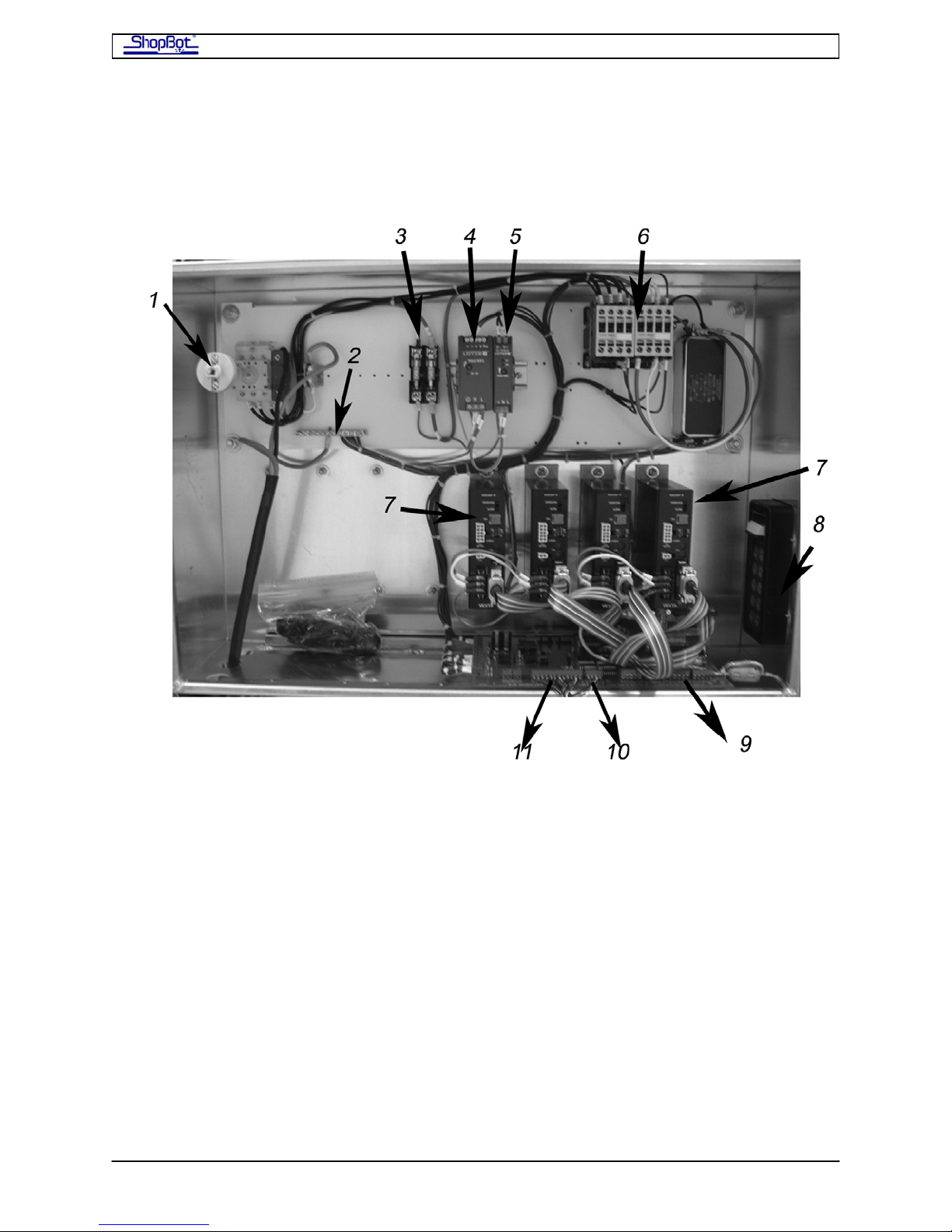
Refer to the labeled picture of the PRSalpha Control Box on the next page.
The Contactors, located at the top of PRSalpha Control Box, are the large relays that control
power to the equipment. They are controlled by the e-Stop and by software. The size of the
contactor may vary with the power requirements of the device it is powering. Additional
contactors for additional devices (example, second router or spindle) are added to the left of
the standard contactors.
The Fuses in the PRSalpha Control Box (US 60Hz power) are dependent upon the setup:
Porter Cable router (single): 1 30A fuse, 1 15A fuse
Porter Cable routers (two): 1 30A fuse, 2 15A fuses
Colombo Spindle: 1 30A fuse, no other fuses (Colombo protected by fused disconnect before
the PRSalpha Control Box.)
Troubleshooting: Although the fused disconnect should protect the PRSalpha Control Box, if
you lose power to everything in the PRSalpha Control Box, please check the fuses and
replace if necessary.
PRSAssembly080922.doc Copyright 2007,2008 ShopBot Tools, Inc
Page 54
ShopBot PRS Assembly Manual Page -54
Inside the PRSalpha Control Box
Your box may not be exactly the same as illustrated depending on the model.
1. Disconnect switch
2. Grounding strip
3. Fuses
4. 24v Power Supply
5. 12v Power Supply
6. Contactors
7. Motor drivers – 4
8. Roxtec Fixture
9. Inputs/Outputs
10. to separate E-stop switch
11. to 3-Button Pendant
PRSAssembly080922.doc Copyright 2007,2008 ShopBot Tools, Inc
Page 55
ShopBot PRS Assembly Manual Page -55
Open the Roxtec Fixture
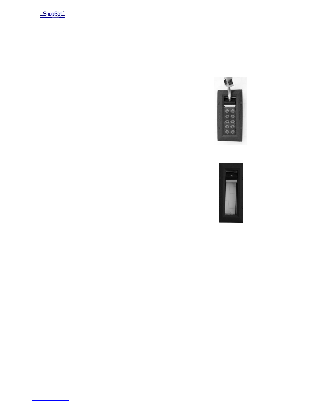
You will be routing cables through the Roxtec Wire Management Fixture attached to the side
of the PRSalpha Control Box. This device gives all wires a tight entry and will seal your
PRSalpha Control Box against dust and debris.
Take a screw driver to lever open the pivot seal of the Roxtec
fixture. There is no screw; just pry it open.
Remove all of the gaskets from the Roxtec fixture.
Once you have attached all of the cables inside the PRSalpha Control Box, you will run the
cables through the gaskets and tighten the fixture to keep dust out of the PRSalpha Control
ox. You may need to run more than one of the smaller cables in the same gasket. B
Plug the Motor Cables into Drivers
Bring the motor cables through the Roxtec opening and plug them into to the drivers which
are the black boxes arrayed horizontally in the PRSalpha Control Box (#7 in the open
RSalpha Control Box illustration shown earlier). P
Plug each motor cable into its driver. The white plug fits the white receptacle on the driver
only one way. Make sure it is aligned correctly and fully seated. in
Fro tm he entry point of the cables:
• X1 (one red tape) and X2 (two red tapes) go to the two drivers at the far right. As
those two drivers are both on Channel 1 (they move simultaneously), an X motor
cable can be plugged into either driver.
• The Y motor cable (blue tape) is plugged into Channel 2, the 3rd driver from the
right.
• The Z motor cable is plugged into Channel 3, the 4th driver from the right.
• Additional motors (Accessory Z, etc.) would be plugged into the additional drivers to
the left of the 4 standard drivers.
PRSAssembly080922.doc Copyright 2007,2008 ShopBot Tools, Inc
Page 56
ShopBot PRS Assembly Manual Page -56
Connect the Emergency Stop Switch and the 3-Button Pendant
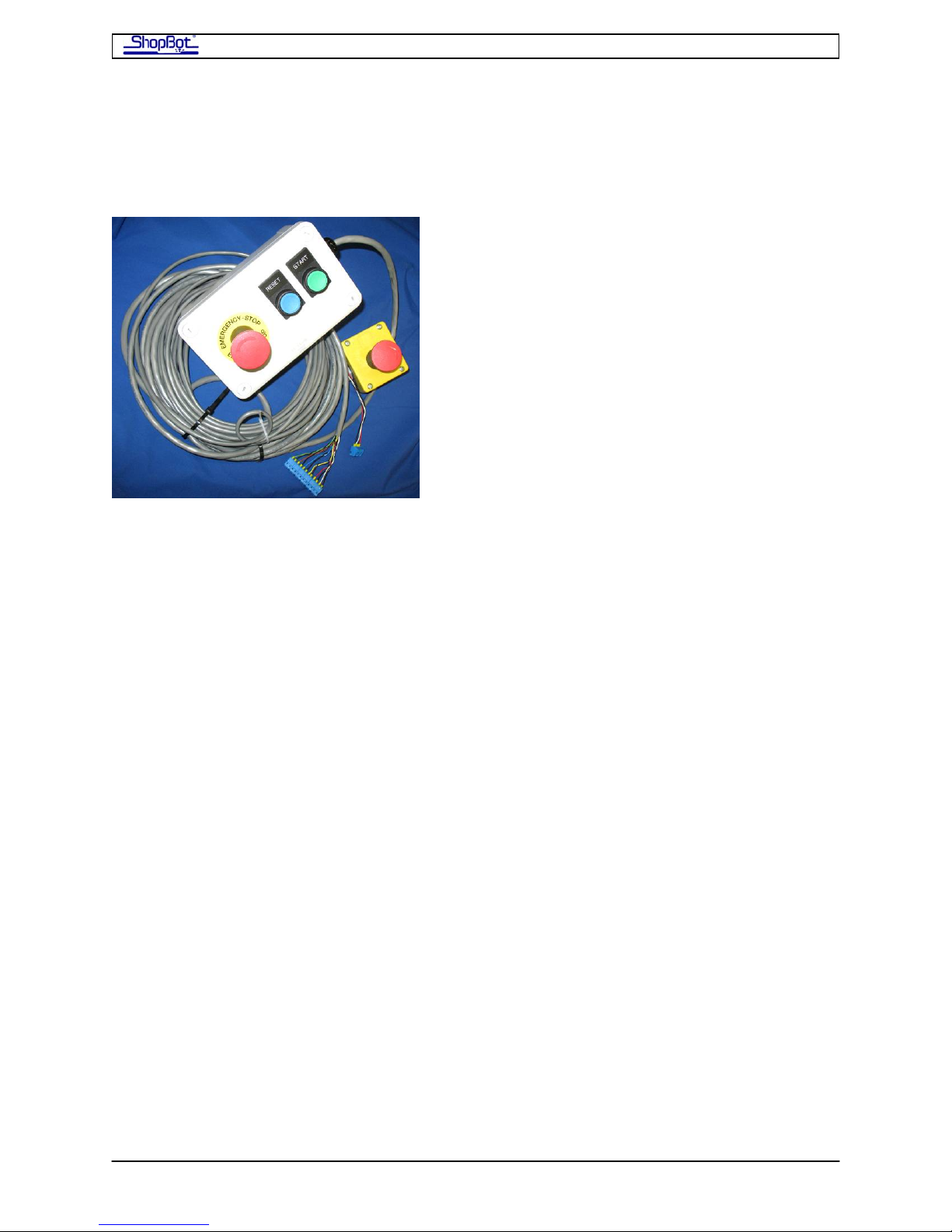
The 3-Button Pendant and the separate E-Stop are bundled together for shipping. Both
must be attached in order for the E-Stop and the 3-Button Pendant to function. Order of
attachment does not matter.
The ShopBot 3-Button Pendant allows you to place the reset, start and extra emergency
stop buttons at a convenient location away from the PRSalpha Control Box. It has been
prewired so that hooking it up to your PRSalpha Control Box entails plugging the terminal
block from the pendant into the control board inside the PRSalpha Control Box. Your
PRSalpha Control Box may differ slightly from pictures in the manual depending on which
model you have. If you have a 3-Button Pendant, your PRSalpha Control Box will not have
Start/Reset buttons.
The separate E-Stop Switch also comes fitted with a terminal block that plugs into the
Control Board. Power for the router or spindle is routed through the PRSalpha Control Box
safety controls so that activating the E-stop by hitting the RED BUTTON will stop the
movement of the carriages and power down the router or spindle. We suggest mounting this
to the gantry on your machine in an easy-to-access location. See section on Mounting the
E-Stop Switch.
Note: If you try to run the ShopBot without the E-Stop connected, Input #4 will flash red
on the computer screen and the ShopBot Control Software will not allow the ShopBot to
move.
PRSAssembly080922.doc Copyright 2007,2008 ShopBot Tools, Inc
Page 57
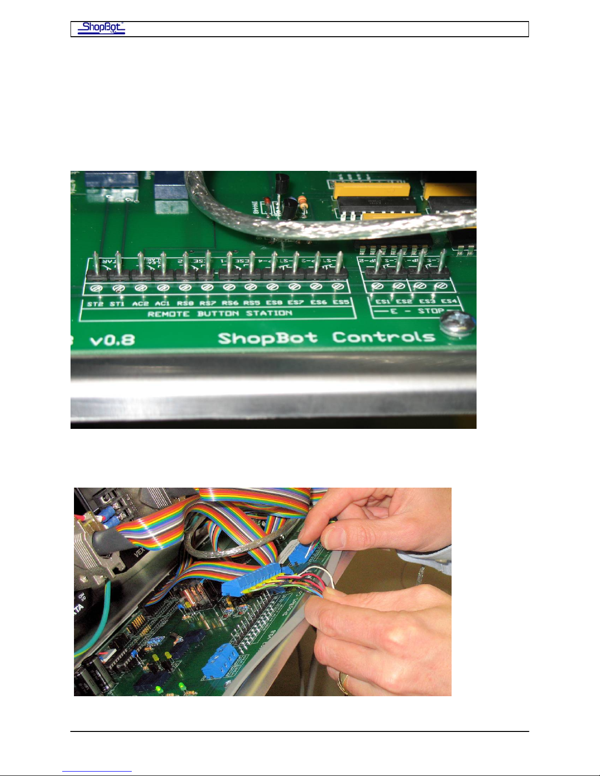
ShopBot PRS Assembly Manual Page -57
Installation
Run the cables from the 3-Button Pendant and the separate E-stop switch into the PRSalpha
Control Box through the Roxtec opening and plug in the terminal blocks as shown below.
Below: The PRSalpha Control Box before the terminal block from the 3-Button Pendant is
attached. Note that the terminal block for the separate E-Stop has not been attached yet.
Below: The terminal block from the separate E-Stop has been plugged in and the 3-Button
Pendant block is being positioned.
.
PRSAssembly080922.doc Copyright 2007,2008 ShopBot Tools, Inc
Page 58
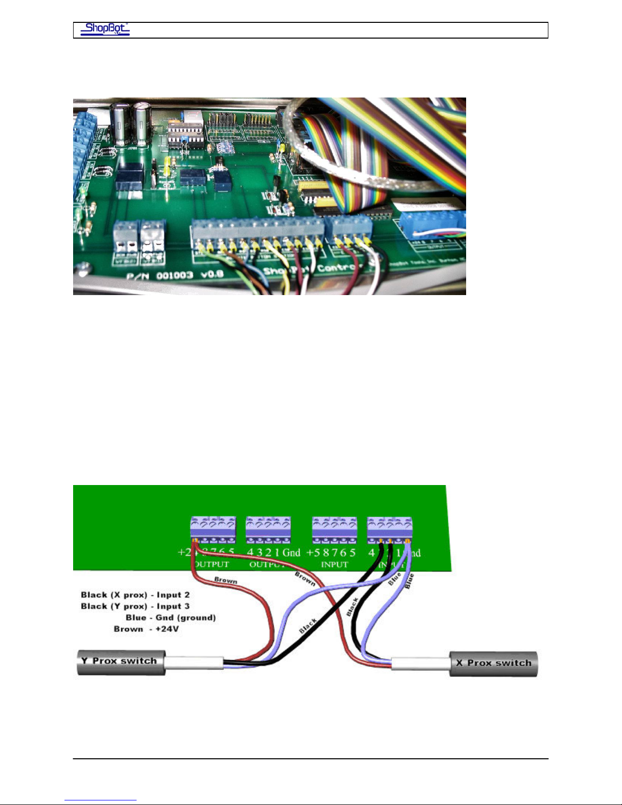
ShopBot PRS Assembly Manual Page -58
Below: Terminal blocks from the 3-Button Pendant and from the separate E-Stop in place.
Connect Cables from the Proximity Switch and Z-zero Plate
Run the cables from the proximity switches and the Z-zero plate through the Roxtec
opening into the PRSalpha Control Box.
Inside the PRSalpha Control Box, take the Proximity Switch cable for the X-axis and place
its black wire into Input 2 on the blue terminal block on the control board. Then take the
Proximity Switch cable for the Y-axis and place its black wire into Input 3 on the same blue
terminal block on the Control Board. The blue wires from both of the switches are placed in
Gnd (ground). The brown wires from both of the switches will be placed in the +24V
position on the blue output terminal block. Note that the terminal blocks can be removed to
make wire insertion easier.
When the PRSalpha Control Box is powered up a red LED in the body of the proximity switch
out on the tool will stay bright until it is triggered by coming near a target.
PRSAssembly080922.doc Copyright 2007,2008 ShopBot Tools, Inc
Page 59
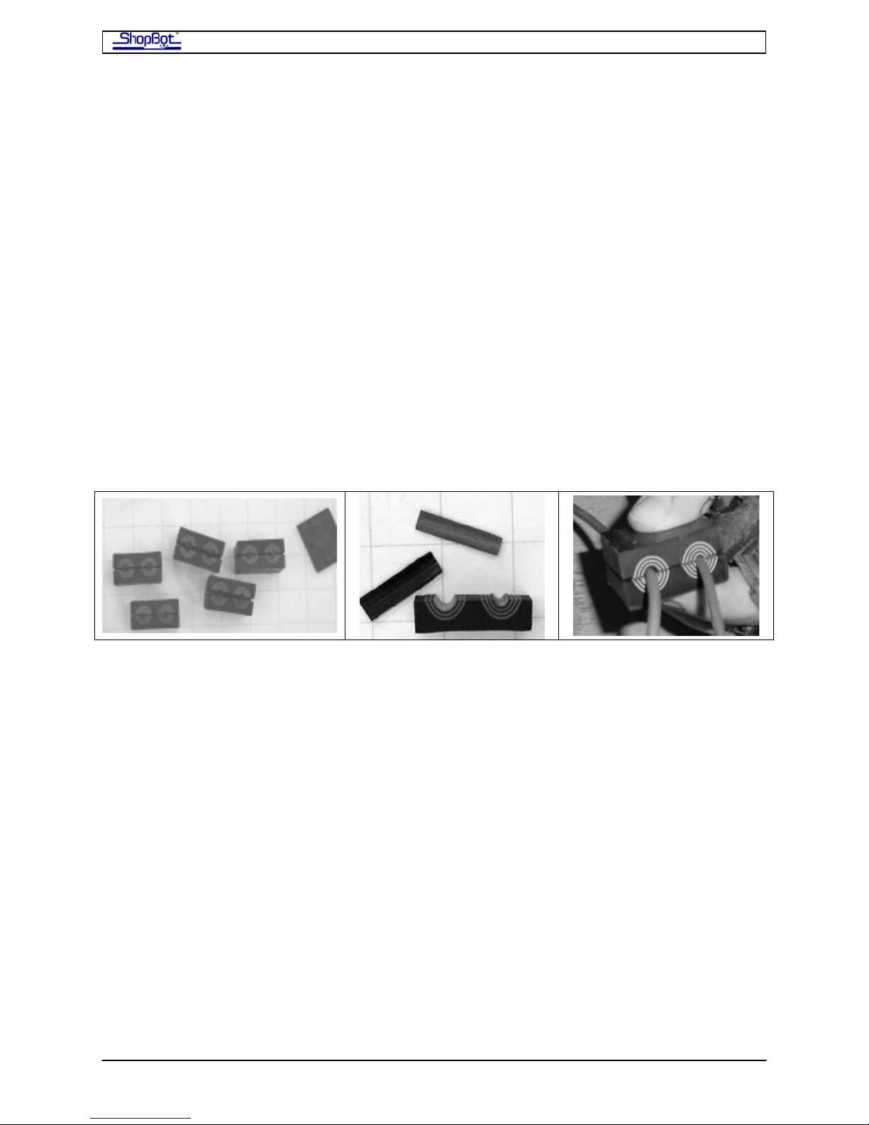
ShopBot PRS Assembly Manual Page -59
Now also plug in the Z-zero plate. The black wire goes in the Input#1 terminal and the
white (or green) wire goes into a ground terminal (Gnd; you can use the one on the Input
terminal block or the one on the Output block). The red wire goes to 5+ (it is only used by
the Digitizing Probe).
There is USB cable connector for attaching the USB cable that will connect your PRSalpha
Control Box to your computer. It is a short cable that exits on the right side of the Control
Board. Plug the longer 10ft cable supplied with your ShopBot into this connector and run the
longer cable out of the PRSalpha Control Box through the Roxtec fixture. Do not plug the
USB cable into your computer at this point.
Seal the Cable Entry
When you have attached all the cables in the PRSalpha Control Box, it’s time to put the
gaskets around them and close up the Roxtec fixture.
The Roxtec system is designed to keep dust out of the PRSalpha Control Box. Take a
moment to fit each of the cables into a gasket so that the cables fit snugly and the two
halves of the gasket close well. It may be necessary to run two of the smaller cables
through a single gasket. This also provides an element of strain relief if the cables are
inadvertently pulled.
• The blue and black layers of the gaskets are layered like an onion. Take out the blue
and black layers out one at a time (alternating sides) until cable fits snugly in the
gasket.
• Position each gasket with cable into the fixture. Apply a small amount of the
lubricant on the outside of each gasket so the parts are slightly sticky. When all the
cables are placed, fill in with the rest of the empty gaskets.
• Fit the shim into the top of the 5 gaskets.
• Using a screwdriver, close the pivot to seal the Roxtec.
Ground the ShopBot PRSalpha
The Table of the ShopBot should be grounded to System Ground at the power box that
supplies the PRSalpha Control Box. Attach the grounding wire (14-16 gauge) at a
convenient bolt on the table, making sure to scratch off paint under the bolt.
Remember that your dust collection system should also be grounded to the System Ground.
See alpha Dust Skirt Documentation for details on grounding the alpha Dust Skirt hoses to
the Dust Collection device.
PRSAssembly080922.doc Copyright 2007,2008 ShopBot Tools, Inc
Page 60

ShopBot PRS Assembly Manual Page -60
Connect the USB cable from PRSalpha Control Box to computer
If you have not installed the ShopBot Control Software on the computer, do it now. This will
install the driver for the USB cable.
On many computers, there are multiple slots for the USB cable. Once you have decided on
the one you are going to use, always plug the ShopBot USB cable into the same slot. Plug
the USB cable into the USB port on your computer.
The USB cable provided is 10 feet long. If it is necessary to increase the length of the USB
cable, use a USB 2.0 hub at the junction between the cable sections. Using a cable longer
than 10 feet without a hub as a booster may result in loss of signal or increased electrical
interference.
PRSAssembly080922.doc Copyright 2007,2008 ShopBot Tools, Inc
Page 61
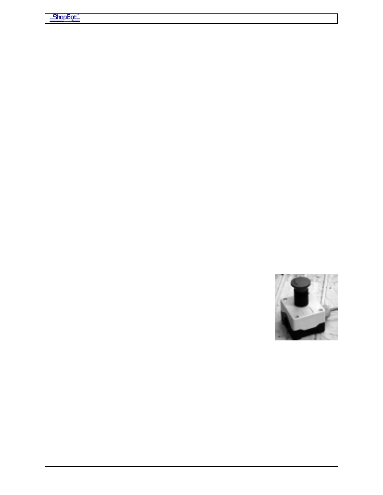
ShopBot PRS Assembly Manual Page -61
Hooking Up Your PRSstandard
Plug the Motor Cables into your PRS Standard Control Box
Remember the earlier warning…your PRS Standard Control Box should now be turned off
and unplugged, correct?
Lay the PRS Standard Control Box down on its side (connectors down) and remove the two
screws holding on the right side panel. Pull off the side so that you can work on the Control
Board.
As you are plugging the motors wires into the PRS Standard Control Box, note that the
connectors are keyed and will only fit one way. Make sure they are fully inserted and locked
into position.
• The X1 (single red tape) motor cable goes into the connector at the top of the driver
board visible at the back of the PRS Standard Control Box labeled X1.
• The X2 (double red tape) connects into the X2 connector, second from top.
• The Y (blue tape) cable goes into the Y connector, third from top.
• The Z (white tape) cable plugs into the Z connector, fourth from top.
• A second Z motor (yellow tape) plugs into the A driver connector, bottom.
Connect the Cable from the Remote-Stop Switch
The PRSstandard comes with a Remote Stop Switch (Stop). Hitting
this ‘Stop’ button will immediately stop the motion of your
PRSstandard tool and keep it stopped until the switch is unlocked.
Power to the electrical cutter on your ShopBot is NOT turned
off by this button.
At the very back of the board, you will see 4 blue connectors with screw terminals. These
blue connectors can be removed to install wires…just pull straight up on them. After you’ve
made the connections, carefully place the wires back in the same position. Notice that the
terminals are labeled on the circuit board underneath.
The 2 blocks towards the bottom of the box are the connectors for ‘Inputs’. The 2 toward
the top are for ‘Outputs’. At this time, we will just be dealing primarily with the Input plugs.
The Stop button has two, normally closed switches (white/red; black/green). We will wire in
only one switch using the black and white (was green in older models) wires.
The white wire from the Remote-Stop is connected to the Ground connection at the left side
of the Input connector. The Black wire is connected to Input terminal #4, which corresponds
to Input Switch #4 in your ShopBot Software. Using a tiny screw driver, snug up the wires
into the correct location.
PRSAssembly080922.doc Copyright 2007,2008 ShopBot Tools, Inc
Page 62
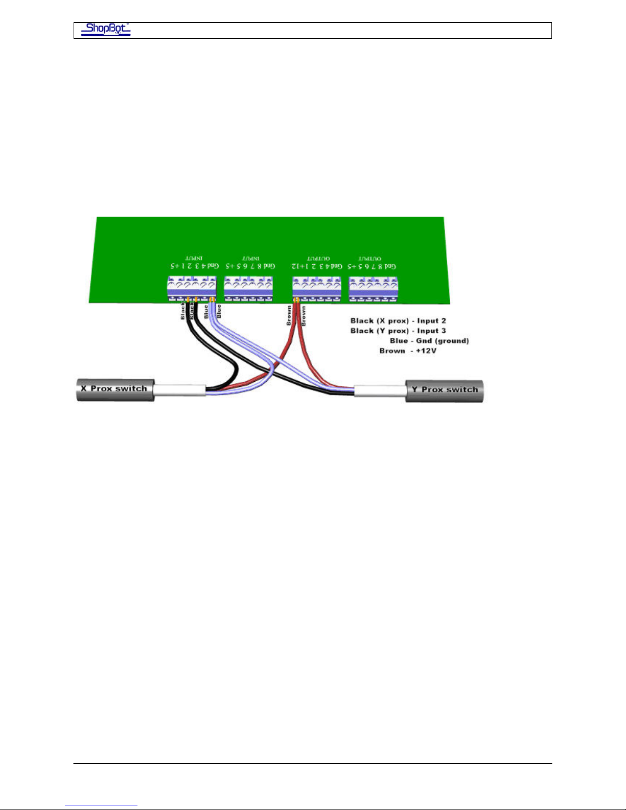
ShopBot PRS Assembly Manual Page -62
Connect the Cables from the Proximity Switch and Z-zero Plate
Inside the PRS Standard Control Box, take the Proximity Switch cable for the X-axis and
place its black wire into Input 2 on the blue terminal block on the control board. Then take
the Proximity Switch cable for the Y-axis and place its black wire into Input 3 on the same
blue terminal block on the Control Board. The blue wires from both of the switches are
placed in Gnd (ground). The brown wires from both of the switches will be placed in the
+12V position on the blue Output terminal block. Remember that the terminal blocks can be
removed to make wire insertion easier.
When the PRS Standard Control Box is powered up, a red LED in the body of the proximity
switch out on the tool will stay bright until it is triggered by coming near a target.
Now also plug in the Z-zero plate. The black wire goes in the Input#1 terminal and the
white (or green) wire goes into a ground terminal (Gnd; you can use the one on the Input
terminal block or the one on the Output block). The red wire goes to 5+ (it is only used by
the Digitizing Probe).
There is USB cable connector for attaching the USB cable that will connect your PRS
Standard Control Box to your computer. It is a short cable that exits on the right side of the
Control Board. Plug the longer 10ft cable supplied with your ShopBot into this connector. Do
not plug the USB cable into your computer at this point.
Ground the ShopBot PRSstandard
The ShopBot Table should be grounded to System Ground at the power box that supplies
the PRS Standard Control Box. Attach the grounding wire (14-16 gauge) at a convenient
bolt on the table, making sure to scratch off paint under the bolt.
Remember that your dust collection system should also be grounded to the System Ground.
See alpha Dust Skirt Documentation for details on grounding the alpha Dust Skirt hoses to
the Dust Collection device.
PRSAssembly080922.doc Copyright 2007,2008 ShopBot Tools, Inc
Page 63

ShopBot PRS Assembly Manual Page -63
Connect the USB cable from PRS Standard Control Box to the
computer
If you have not installed the ShopBot Control Software on the computer, do it now. This will
install the driver for the USB cable.
On many computers, there are multiple slots for the USB cable. Once you have decided on
the one you are going to use, always plug the ShopBot USB cable into the same slot. Plug
the USB cable into the USB port on your computer.
The USB cable provided is 10 feet long. If it is necessary to increase the length of the USB
cable, use a USB 2.0 hub at the junction between the cable sections. Using a cable longer
than 10 feet without a hub as a booster may result in loss of signal or increased electrical
interference.
The Remote Stop Switch
The Remote Stop Switch comes with a long cable so that the switch can be mounted in a
convenient location for your set up. Keep the remote stop switch away from devices that
have their own power source, such as the spindle or router, or a vacuum system.
Some ShopBotters carry the Remote Stop Switch with them as they move about their tool.
Others mount it on the tool.
Mounting the Switch
• Decide WHERE to mount the switch. One good spot for mounting is on the front side
of the X-Car, with the cable run to the back of the tool through the center of the
beam. Other possible locations are on the side of the table, at your computer station,
or on the wall near the ShopBot.
• Decide HOW you want to attach it. You may use mounting tape, Velcro, or screws.
If you use screws to mount the Remote Stop Switch:
• Open the box by removing the 4 screws on the front cover and insert the mounting
screws into the holes in the back of the box.
• Re-attach the cover and make sure that the screws are tightened all the way. If the
cover isn’t tightened completely, the switch may not work properly. The E-Stop
switch itself is designed to fit together only in the correct manner. However, if you
take it apart, make sure the screws are completely re-inserted and the top drawn
tight on the seal.
• Note that when the lid is fitted back on the box, the switch plungers must slide inside
the guide cylinder of the plunger mechanism.
PRSAssembly080922.doc Copyright 2007,2008 ShopBot Tools, Inc
Page 64
ShopBot PRS Assembly Manual Page -64
Mission Accomplished!
You might have thought you'd never get here, but: “Mission Accomplished!”
PRSAssembly080922.doc Copyright 2007,2008 ShopBot Tools, Inc
Page 65

PRS Assembly Appedix Page -1-
Assembly Appendix
Stopping the ShopBot
Test Spin
Surfacing the Table
Squaring and Adjusting the X-Car
Table Drawings
AssemblyAppendixintro.doc Copyright 2008 ShopBot Tools, Inc
Page 66

PRS Assembly Appedix Page -2-
AssemblyAppendixintro.doc Copyright 2008 ShopBot Tools, Inc
Page 67

Stopping the ShopBot Page -1-
Stopping the ShopBot
Using the PRSalpha E-STOP
You must be running ShopBot Control Software 3.5.x or higher for these instructions to
apply. Go to www.shopbottools.com
Once it is properly attached, hitting the E-Stop Switch will instantly stop the movement of
your X, Y and Z gantries. The power to the spindle/router, motors, and the rest of your tool
will be cut off.
After you have activated the E-Stop Switch, to go back to work you will n eed to
• Release the red button on the E-Stop by rotating it
• Press the RESET button on the PRSalpha Control Box to send power to the
spindle/router and motors on your tool.
• Clear the message box in the control software by pressing “Quit”.
• Re-zero the tool to make sure its location is correct because the motors were turned
off
You can return to the location in the file you were cutting and continue from there by using
the [FG] Command to start the file in the ‘G’oTo mode.
to download the latest control software.
Use 3-Button Pendant
Place the 3-Button Pendant in a convenient spot for you to operate your machine. Both the
Reset button and the Start button for your Spindle/router are now located on the 3-
Button Pendant, not on the PRSalpha Control Box. The E-Stop button on your 3-Button
Pendant and the separate E-Stop Switch function alike
Using the PRSstandard Remote Stop Switch
You must be running ShopBot Control Software 3.5.x or higher for these instructions to
apply. Go to www.shopbottools.com
Once it is properly attached, hitting the Remote-Stop Switch will instantly stop the
movement of your X, Y and Z gantries. Because the spindle/router is connected
independently to power, the Remote Stop Switch will not turn off the spindle/router.
After you have activated the Remote Stop Switch, to go back to work you will need to
• Release the red button on the E-Stop by rotating it
• Clear the message box in the control software by pressing “Quit”.
• Re-zero the tool to make sure its location is correct because the motors were turned
off
You can return to the location in the file you were cutting and continue from there by using
the [FG] Command to start the file in the ‘G’oTo mode.
to download the latest control software.
StopShopBot080916 Copyright 2008 ShopBot Tools, Inc
Page 68

Stopping the ShopBot Page -2-
Stopping with the Space-Bar or “S” key
In a non-emergency situation, you might want to stop the movement of the carriages
without cutting power to the motors. This can be done by hitting the SPACE BAR or the
“S”top key. This will stop the movement of all three axes. If the tool is moving slower than
3”/sec, the router bit will stay in its current position. If the tool is going faster than 3”/sec,
the movement speed of the X and Y axes will be ramped down, and the cutter will be pul led
up and out of the material. The spindle/router will be not shut down.
In both cases, the computer will display a message screen to prompt you for what to do
next.
The presence of a Remote Stop Switch does not alter the need to good safety procedures
for operating your ShopBot. You should always stand clear of the tool when it is in
movement, preferably positioning yourself near the computer controlling th e operation. A
Personal Robotic Tool can be a very safe power tool as long as all safety procedures are
followed.
StopShopBot080916 Copyright 2008 ShopBot Tools, Inc
Page 69

Test Spin Page -1-
Take a Test Spin
Next we'll go for a quick trial spin with your tool and do a few tests to make sure things are
working as they should be. Then you'll be ready to start putt ing your ShopBot to work for
you!
Run Your ShopBot Now and Check out Some of its Basic Functions.
Start the Control Box. If your tool is a PRSalpha, also hit the blue “Reset” button on the box
(this activates the relay systems). Your first moves will just be ' a ir' cuts, so you do not need
to have a bit.
Start the ShopBot Control Software. The icon to start the Control Software is
labeled “ShopBot 3” and should show up on your Windows Desktop. Double
click it to start the software.
If this is the first time you have run the software, you will be prompt ed to
select your tool type from a list. (If you get it wrong, you can correct later with Utilities >
Reset.)
As the ShopBot Control Software begins to start, it should indicate that it is “trying to
connect” to your ShopBot If you have run the software in Preview Mode previously, ju
click the ‘Move’ Switch on the Red Panel to swit ch ou
ove/Cut Mode. The connection process will start.
M
If a connection to a ShopBo
suggestions
for you to try.
t Tool cannot be established, a yellow screen will come up with
t of the Preview Mode and into
st
TestSpinPRS080916 Copyright 2008 ShopBot Tools, Inc
Page 70
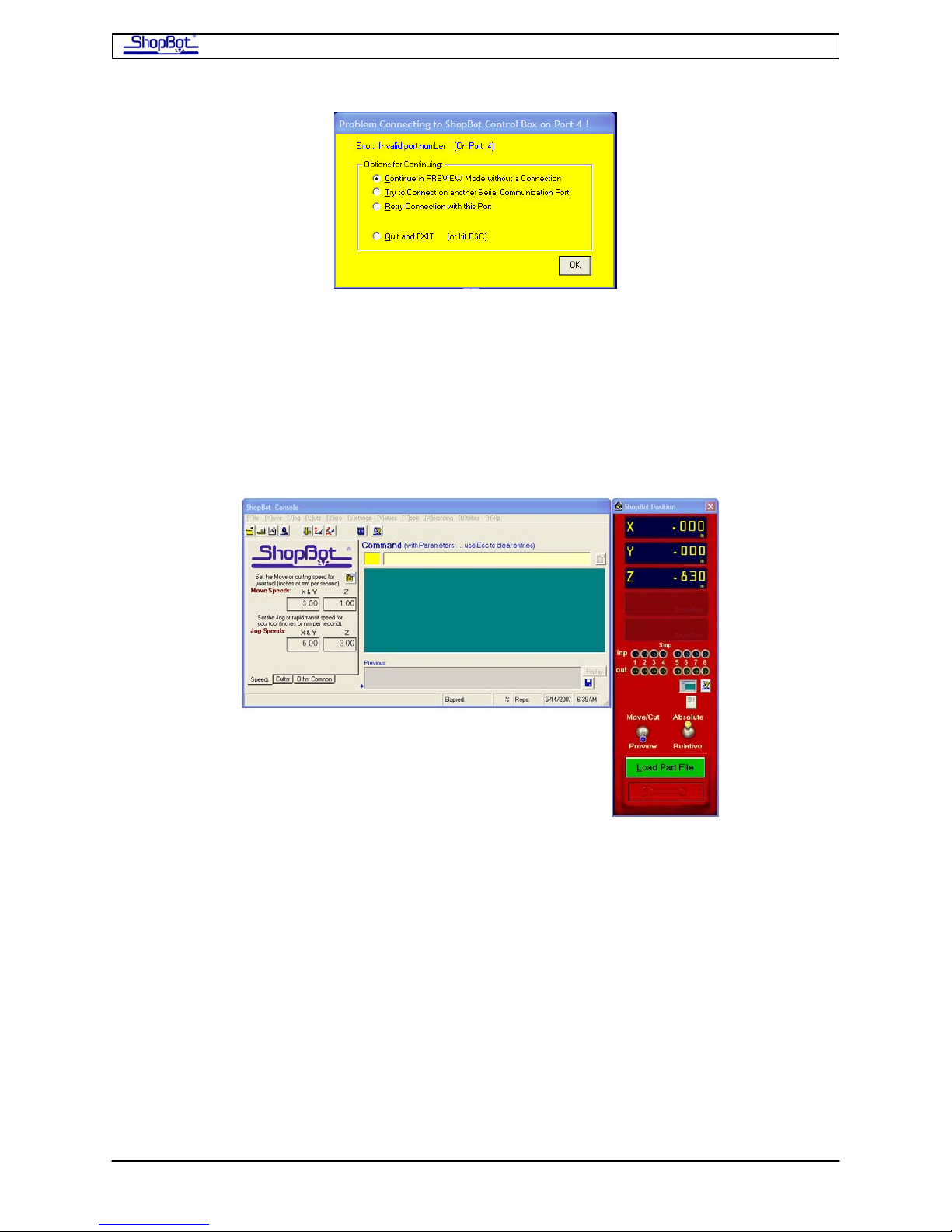
Test Spin Page -2-
The software tries to establish a connection to your ShopBot on a default communications
port number (usually COM4). If the yellow screen appears, choose “Try to Connect on
Another Port” and hit OK. Then click the button to ‘Automatically Find’ your ShopBot. When
the correct port is located, click OK. The connection will be established and the port will be
remembered for future starts.
There is information in the README file on establishing connections is you have a problem,
and also in the Troubleshooting section under Help in the Softwa re.
Once you are connected, the ShopBot Control Software will bring up two Windows. The red
one is the Locations Display for your tool. The second screen is the Control Console which is
the place you to enter Commands to tell your ShopBot what you would like it to do.
You can use the keyboard or mouse to select commands from the Main Menu bar, or you
can enter two letter ShopBot Commands right into the Command Box on the Console.
• Before starting, let’s just check a few settings. First, make sure that the Distance
Switch on the red panel is set to ‘Absolute’ (Up). And, then let’s set the current
location to zero by typing ‘Z3’ at the keyboard (the Location Di spl a y should now
show 0 in all axes).
• ‘Z3’ is an example of a ShopBot 'Command' instruction. From here on, and in the
manual Commands will be indicated with brackets, for example [Z3]. With ShopBot
Commands you only need to type the two letters in the appropriate space. There are
drop-down menus that remind you of the meaning of these Commands letters. This
is fun, so relax and enjoy.
TestSpinPRS080916 Copyright 2008 ShopBot Tools, Inc
Page 71

Test Spin Page -3-
• Now we’ll try a few moves. Before carrying out any of these instructions, make sure
that the area is clear for the power stick to move. And remember, YOU CAN STOP
ANY MOVE BY HITTING THE SPACE BAR!
• Try a 1" Z plunge.
o Use: [MZ] … first type ‘MZ’ as the Command, then put ‘-1’ in for the
parameter. Remember, negative numbers plunge for the Z axis. Then hit
ENTER.
o You should hear a few seconds of warning beeps, then the Z-axis should start
plunging down. It should stop after moving 1" down. You should see the
move on the tool, and the new location should show on the display.
o Now, go another inch down ... you need to use an [MZ] -2 because you'll be
moving 1" further down to the location -2.00. OK...? ... Then, return to your
starting point at a faster (jog) speed with: [JZ] 0. This should give you a feel
for how the Z-axis works.
• Now check out the Y axis in a similar fashion.
o Let’s go 3" in the positive direction on the Y-axis.
o Use: [MY] 3. Your tool should have gone exactly 3" back (away from you on
the Y-axis as you are facing the tool from the front) and the computer display
should indicate a Y location of 3.00.
o Then use [JY] to bring it back
• And give the X axis a try using [MX]. The table/power st ick should move.
The ‘KeyPad’ Control
If all has gone well, it’s time to try the KeyPad Cont rol which is a more convenient way to
move your tool from the Control Console when it is not running a file.
• Hit 'K' which the shortcut to KeyPad C ontrol (full command = [SK]). You should see a
new screen displaying a number of arrow key buttons. You can move your mouse
over any of the items on the KeyPad to get an explanation of what they do. But
basically, you can click on keys to move your tool, or you can use the equivalent
arrow key on you computer keyboard.
• Try driving your tool around with the arrow keys. Use the ESC key when you are
ready to close the KeyPad.
• If you want to Zero the X and Y axes in another location, use the KeyPad control to
move the tool to that location, escape from the KeyPad control, and use the Z2
command to re-zero.
• If all has worked well so far, jog back to the starting point using both ax es. Use: [J2]
0, 0. Your tool should move rapidly back to where you last zeroed it.
TestSpinPRS080916 Copyright 2008 ShopBot Tools, Inc
Page 72

Test Spin Page -4-
Try a Circle
• Do a 6" circle using the built-in circle command: [CC] 6 (The 6 is the only parameter
you will need to provide on the ’Fill-In Sheet’ that comes up). Your ShopBot should
execute a smooth 6" circle.
• Note that the speeds of the motors change as the tool moves through the circle. The
motor speed changes in order to maintain a constant vectored speed at the cutter.
Do an 'Air Cut’ of a ShopBot Part File
Now let’s try running a Part File (a file containing cut ting instructions or ‘tool paths’). We will
do an ‘air cut’, which means to run it in the air above the cutting bed without the router or
spindle running.
• Use: [FP; 'F'ile 'P'art], then use the arrow keys to scroll to the file called
"S_SBLOGO.SBP" and hit ENTER (If you aren’t in the c:\SbParts folder, you will need
to browse to it). All the files which start ‘S_’ are sample files of one sort or another …
you will probably find them interesting and h elpful. Use the [‘F’ile ‘E’dit] Command to
check out what’s in them.
• We'll ignore the parameter settings on the fill-in sheet for the moment ... just hit
ENTER twice again to start air-cutting the file.
• This file cuts the ShopBot logo (normally you would use a 'V' bit), and you can cut it
in all different sizes using the proportion feature in the [FP] Command. Note that the
underline portion of the logo cuts first, followed by the letters. The file en ds with a
couple of 3D moves to carve the shape of the flying wood chips in our logo.
Mount the X-Axis Proximity Switch Targets and Check The Y-Axis
Proximity Switch
With your tool powered up and moving, we can finish up getting the Proximity Switches set
up.
• Now (assuming you have the End Stops in position to keep the car from coming off
the rails) move the car to about 2” from the end of the X track (you’ll do both ends,
so start at either). This is about where we want the limit swit ches to trigger.
• In the prox switch kit there are (2) 1/4”-20 bolts, (2) ¼” flat washers, (2) ¼” nuts,
and (2) 1/4” T nuts. Place the nut on the bolt, the flat washer, followed by the T nut.
Remove the black end caps from the table side and slide the target into the second
slot from the bottom, of the table side extrusion. The target should capture the table
side between the T nut and flat washer. Tighten the bolt until it begins to tighten into
the slot, back off slightly to allow movement side to side.
TestSpinPRS080916 Copyright 2008 ShopBot Tools, Inc
Page 73
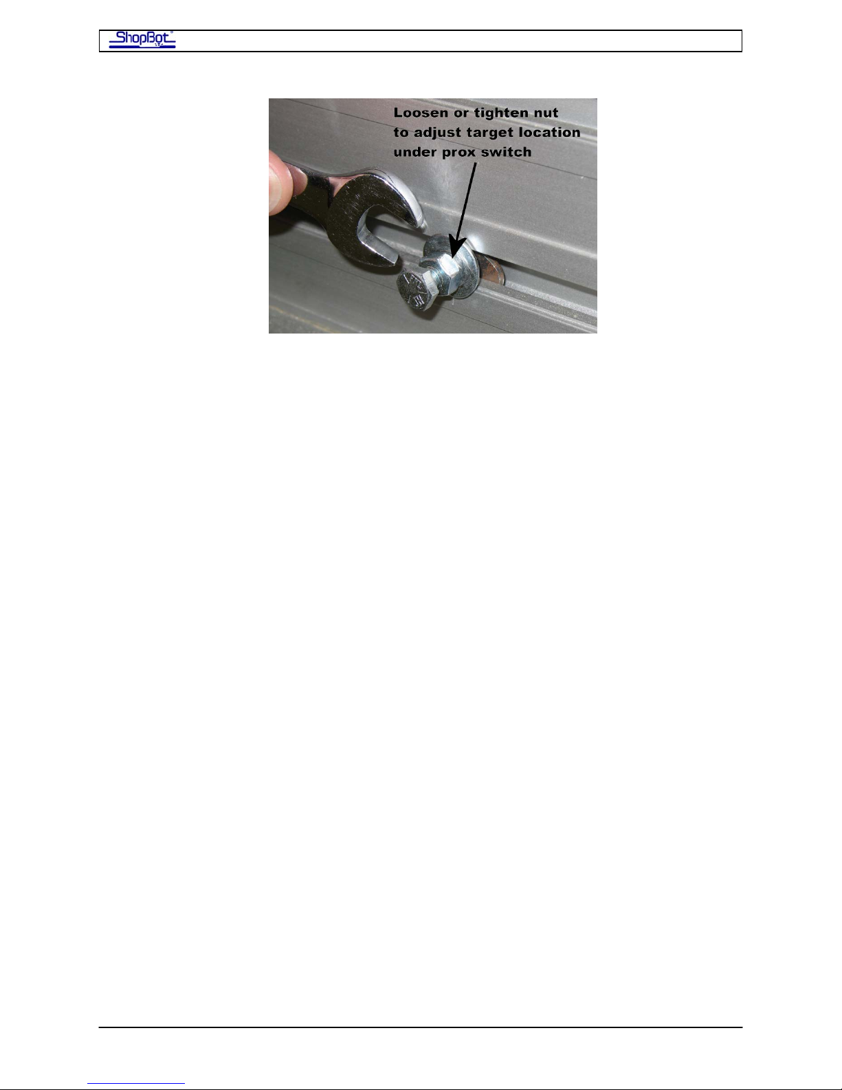
Test Spin Page -5-
• Slide the target along the slot until it is just under the Prox imity Switch on the X car.
Lock the position of the target by tightening down on the top nut and washer.
• Then set the distance between the Proximity Switch and the target to about 2mm by
adjusting the Proximity Switch position using the tw o nuts. In this position, the
Proximity LED should be off.
• Use the KeyPad to back off the Proximity Switch. The LED should come back on. You
can test the “Limit” Function of the Proximity Switches with the KeyPad. First use the
[VN] Command to turn the Limit Switch functionality on. Now use the KeyPad to
drive into the switch. Your tool should stop. After hitting a switch, the KeyPad then
overrides switches if you use it again, so you can drive off the switch. After you have
driven off and released the arrow key. The switches will a gain function as limits.
• Set the Proximity Switch at the other end of the Table.
• Finally, check the Y-Axis Proximity Switches to make sure it is adjusted correctly and
functional.
PartWorks and PartWorks 3D
This can be installed on a separate design computer if you wish. Tutorials will be copied to
your computer as part of the installation process. Go to Start > All Programs > ShopBot >
Tutorials to open them. The accompanying videos are available for download at
www.shopbottools.com > support > documentation
TestSpinPRS080916 Copyright 2008 ShopBot Tools, Inc
Page 74

This page left blank.
Page 75

Surfacing Table Page -1-
Surfacing Your Ta ble
One of the first things you'll want to do after getting your ShopBot together and running is
to smooth your work surface. Here are a set of general procedures for surfacing your table.
There are several ShopBot Commands you will learn about in the process …
You will want to make sure that you followed the instruct ions to square up your Z-axis
before you start. The smoothness of the surfacing you do will depend on the Z-axis being
perpendicular to the table. However, don’t be too disappointed if your surface has distinct
tooling marks. After you've finished this surfacing, you will actually be able to adjust the Zaxis with even more precision because you will have a tool-defined, flat plane to measure
against. The larger diameter the cutter that you us e for surfacing, the less time it will take.
But a wider cutter makes it more likely that you will have t ooling ridges from the process
and increases the load on your router. A .75”- 1.25” diameter bit will probably work well.
This little project is going to generate a lot of sawdust. We’d recommend you get your
dust collector hooked up and running before starting the actual cutting.
The instructions use values appropriate for a table that is exactly 96” X 48”. If your ShopBot
is a different size, the table surface slightly larger or smaller, or you are working in mm,
just replace the ‘96’ and ‘48’ with appropriate dimensions for your table (for example ‘32’
and ‘24’ for a BT). NOTE: If you are using a router bit that does not have a blade for
plunging, you need to plunge to the cutting depth outside of the material, and move into
the material. The instructions will give you suggestions on how to do this.
By this point you should have the table surface material mounted on your ShopBot. You
should have attached the support board to the table with the carriage bolts (recessed)
included in the table hardware. Now, attach a sacrificial b oard to the underlying support
board by countersinking drywall screws. If you can find them, plastic screws countersunk
are a good option. If there are warps in the sacrificial board, check to be sure that all the
screws are tight.
ut Rectangle [CR] Command (with pocketing) in
The table surfacing routine will use the
the ShopBot Software to run a surfacing bit over the entire surface of the sacrificial board.
Remember: The [Esc] key will back you out of a command that you don’t want. Hitting the
Spacebar or the "S" key (and Remote Stop on a PRSstandard) will stop the movement of
the carriages without shutting down power to the router or spindle. The E-Stop on a PRSalpha
will stop movement of the carriages AND shut down power to the spindle/router.
C
SurfacingTable080916 Copyright 2008 ShopBot Tools, Inc
Page 76
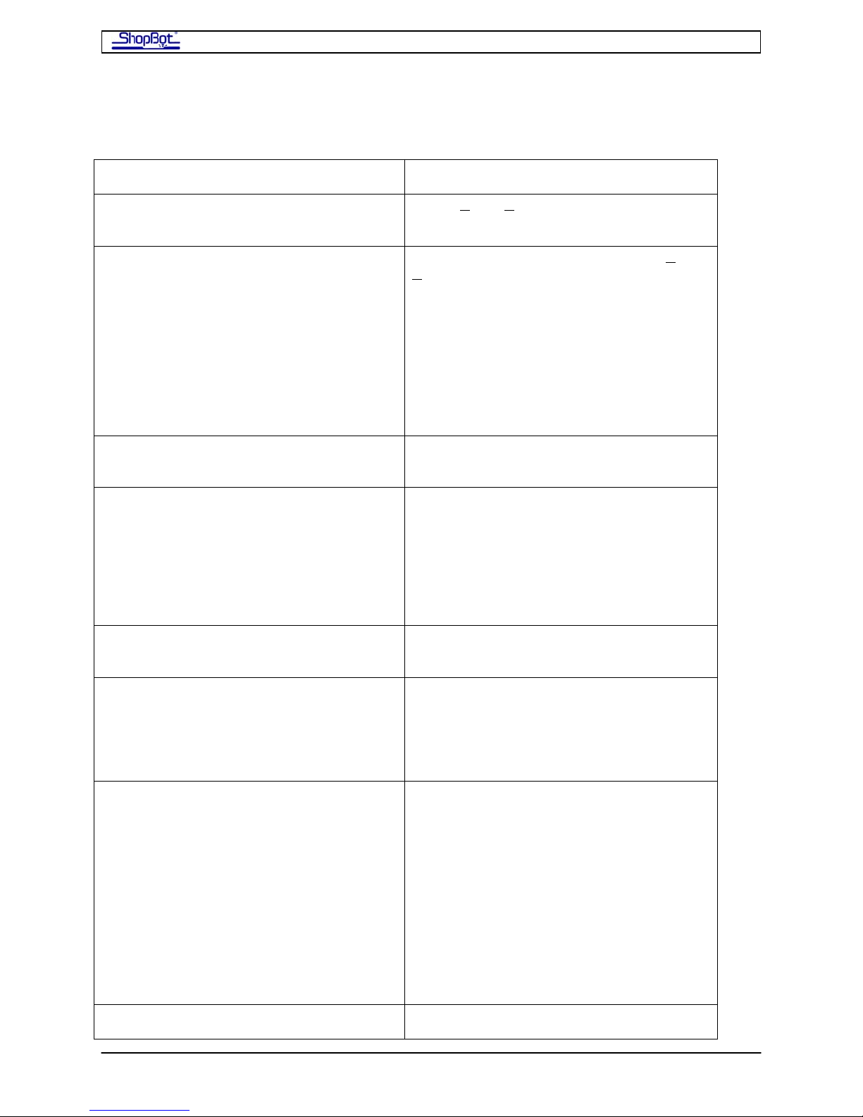
Surfacing Table Page -2-
Steps for surfacing your table …
What
Set the diameter for the bit you are
using
Move the router bit to the starting point
for the X and Y axes at the lower left
corner of the table.
Make that point 0,0 for the X and Y axes
Lower the router bit onto the surface of
the board
Set the surface as 0 for the Z-axis
Raise the bit so that it is about ¼” off the
surface of the table
Send the router across the table
diagonally. Watch carefully for the low
point on the surface of the board.
Send the router to the lower right corner [M2] 96, 0 to Move 2 Dimensions (the
How
[VC] (V
Call up the keyboard control [SK] (S
eyboard or just K). Use your keyboard
K
alue Cutter)
et
arrow keys to move the router into the
lower left hand corner of the table (think
of the little man). Carefully line up the
center of the bit with the corner of the
table. Note: if you are using a bit with
no plunge capabilities, move the bit to
slightly beyond the material so that the
bit plunges outside the material, and
moves into the material to cut.
[Z2] (Zero 2D)
Call up the keyboard control [SK] or
[K]. Use the PageUp and PageDown
keys to raise and lower the Z-axis/router
… move the bit down until it would just
touch the table. Escape out of Keyboard
Control
[ZZ] (Zero the Z)
Call up the keyboard control [SK] or [K].
Use the PageUp and PageDown keys to
raise and lower the Z-axis/router.
[Escape]
[M2] 96, 48 to Move in 2 Dimensions
(the X & Y) to the point that is 96” along
the X axis and 48” along the Y axis. If
your tool is not a 96x48, use the correct
dimensions. Hit Enter to initiate the
move. The router should glide along a
diagonal line and end up at the upper
right corner of the table board. NOTE:
the space after the M2 and the
COMMA are very important.
SurfacingTable080916 Copyright 2008 ShopBot Tools, Inc
Page 77
Surfacing Table Page -3-
of the table. X & Y) to the point that is 96” along the X
axis and 0” along the Y axis [hit Enter to
move]
Send the router across the other
diagonal. Watch carefully for the low
point on the surface of the board.
[M2] 0, 48 to Move 2 Dimensions (the
X & Y) to the point that is 0” along the X
axis and 48” along the Y axis [Enter].
The router should glide along a diagonal
line and end up at the upper left corner
of the table board.
Move the router to what looks like the
lowest area of the table surface.
Again call up the keyboard arrow key
controls [SK] or [K] to move to the
lowest point.
Lower the Z to that point.
[K] and PageDown. Read the Z
location on the screen on the ShopBot
Position screen (red)… it should be a
negative number if this point is lower
than your original start point.
Zero the Z-axis to reflect this new lowest
[ZZ]
point
Raise the Z and Jog Home to 0,0
[JH] This command automatically pulls
the Z up and moves you at jog speed
back to the home location in X and Y.
Now you are ready to try the diagonals
with the router on to see if the cutting
head is at the right height to remove a
TURN ON THE ROUTER/SPINDLE
For PSRalpah Ctrl-1 to Activate; then hit
Start Button.
small bit of material from the entire
surface
[MZ] 0 to Move the Z to 0.
[M2] 96,48 [Enter] will Send router
across diagonal to the point 96, 48 (You
may have to add an inch to the length or
width if you plunge outside the material.)
If the cutter removes a bit of material
from all across the diagonal, you are at
the right Z height. If not, lower the Z
SurfacingTable080916 Copyright 2008 ShopBot Tools, Inc
Page 78
Surfacing Table Page -4-
slightly and return to 0,0 [M2 0,0] You
should confirm your final height by
cutting the other diagonal … you’ve done
this before, right ?
Go back to home after getting the depth
[JH]
set with diagonal passes
Now, you are ready to surface the table.
NOTE: You may want to try this up in the
[CR] for Cut Rectangle.
air first before you really cut the surface,
(you can do a few passes to make sure
all is going right, then stop the action
with the space bar, jog home [JH], and
start over … you can also try this in
Preview Mode first)
Fill in the blanks on the parameter sheet:
Length x 96, length y 48, T (for True), Use dimensions for your tool if not a
96x48.
1 (direction of cut=clockwise), Start* 4, *set to 4 to start in bottom left
Plunge per pass (set depth slightly below
predetermined lowest point on table to
be surfaced, say -.025), Reps 1,
Use the tab keys to move between rows
YOU’RE OFF AND RUNNING ….
of options, set Pocket function by
marking box [X] with the spacebar. Set
“Z Plunge Offset 0” by checking box with
spacebar. Accept [Enter] then [Enter]
again to run it.
Tools > TS
There is also a Table Surfacing Tool in the ShopBot Software under Tools. This is a
simplified version of what you’ve just done and will be useful for routine re-su rfacings.
SurfacingTable080916 Copyright 2008 ShopBot Tools, Inc
Page 79
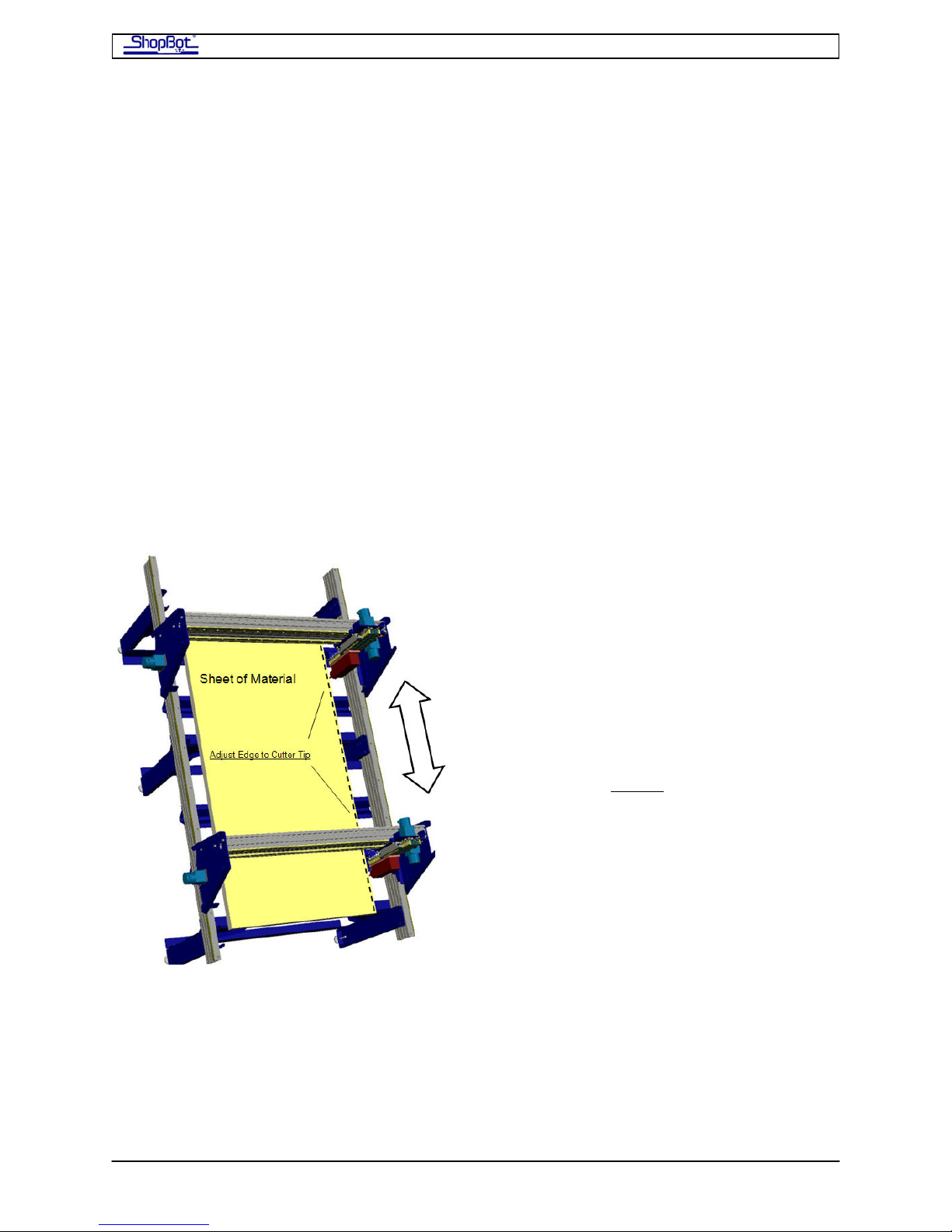
Squaring and Adjusting the X-Car Page -1-
Squaring and Adjusting the X-Car
There are a number of good ways to evaluate whether your tool is “square”. The first is just
to cut a large rectangle, the bigger the better, and measure the diagonals. They should be
equal. Short of cutting something out, you can inscribe a shallow, large square or rectangle
(e.g. 30x50) on your table surface (or chuck up a pencil and draw one) and measure the
diagonals. Alternatively drill 4 holes at the corners of a square and measure t he diagonals.
In all cases, if the diagonals are equal your tool is cutting square.
The technique decribed below provides a straightforward method to help you in itially square
your tool. Use it to get started. However, the “proof is always in the pudding.” Use the
approach above when you are ready to fully ‘evaluate’ square.
Use a Square Sheet
This initial squaring technique can be used either with or without the motors engaged. If
you have had difficulty getting the wheels exactly aligned in the previous steps, then you
may want to lower and disengage the motors from the rack to make a first pass at adjusting
the alignment. You basically want to make sure the X-Car in its relaxed or natural position is
pretty square. If things already look about right, then leave the motors engaged.
You will need to have mounted y o ur router or
spindle to use this squaring technique. Put a
cutter with a v-tip or point in the collet. The
only other thing you will need is a large square
sheet of material. It should be a sheet that
you are confident is square because you have
measured the diagonals, say a 4x4 or 4x8
piece of plywood. [NOTE: Sheets from the
factory are not necessarily square. Measure
each edge to make sure they are equal, THEN
compare the diagonals. The bigger the size the
better, so a large square
than a carpenters square. In fact, the average
carpenters square is not very square. Check it
well if you are using one.]
Move the YZ Car to one end of the Y axis,
bring the tip of the cutter down to the edge of
the material, and align the sheet up and down
the X axis by moving The X-Car up and down
the rails, checking the position of the sheet at
the tip of the cutter.
sheet works better
SquaringXCar080916 Copyright 2008 ShopBot Tools, Inc
Page 80
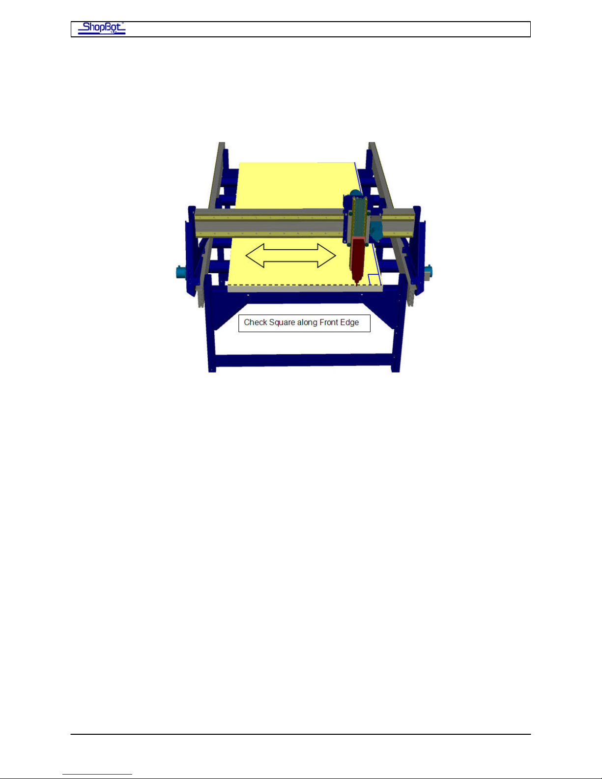
Squaring and Adjusting the X-Car Page -2-
Now, because you’ve gotten the board parallel to the X axis, the short (Y) edge is square to
the X. You can move the carriage down to one end of the sheet and move the tip of the
cutter along the short edge, moving the YZ Car. By observing the tip of the cutter as it
moves along the short edge, you will be able to evaluate the square of the two axes on the
tool.
Relaxed Alignment vs Powered Alignment
Square is maintained on your tool by the 2, X-axis motors. The motors always move
absolutely identically and they keep the X-Car perfectly square when they are powered. The
X-Car itself, when not locked into position by the motors, is not designed to be capable of
maintaining the alignment on its own. In th e ideal world, the X axis will always ‘relax’ into a
square position when powered off. But in practice, because the motors and gearboxes have
a lot of friction, there may not be an exact, relaxed alignment position of the carriage and it
will be possible to push one or the other end out of alignment.
To get the tool square with the motors installed and engaged, start powered off, push the
carriage back and forth a few times from the center and let it take as natural an alignment
position as possible. Do this over the edge of your sheet so you can check square. Your
relaxed alignment should be within about 1/8” of square across the table, as indicated by
your cutter tip moving up and down the Y edge of the sheet. If you are further out of
alignment than this, visit the “Making Adjustment” section below.
Once the alignment is close and continuing with the motors powered off, push the one end
of the car slightly to bring the whole gantry into perfect square with the board. You may
need to lock one or both ends with clamps to manage this. Then, when you’ve got it square,
turn the power to on to the Control Box, and if a PRSalpha, hit the Reset Button. The
motors will power on and lock into position. Your tool is now square in X and Y, and it will
remain square whenever it moves until the power is removed.
SquaringXCar080916 Copyright 2008 ShopBot Tools, Inc
Page 81
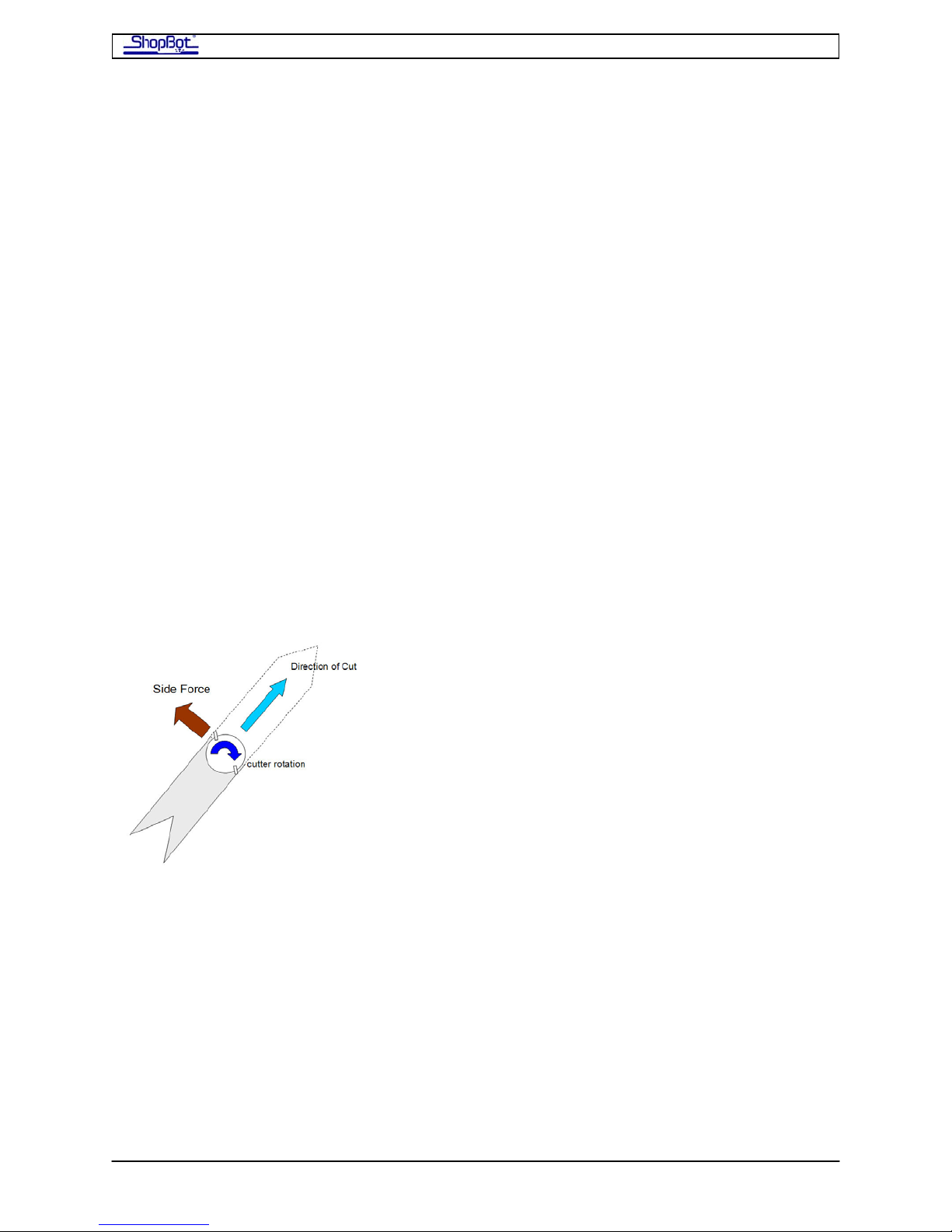
Squaring and Adjusting the X-Car Page -3-
Setting the End Stops So Your Tool Will Always be Square
Because the X-Car is not intended to be able to physically maintain alignment when the
power is off, after a period of being powered down you cannot be certain that in a busy
shop the carriage has not been bumped a little out of square. So, you need a system for
guaranteeing square each time you restart the tool. The mechanical End Stops do this for
you.
First let’s get the End Stops installed perfectly square at the bottom end of your tool. Do
this by driving the X Car, using the KeyPad mode in the software, down to the bottom (X =
0) end of the tool. Slow down when you get close, and move the car to the point that each
wheel bearing is about ¼” from the end of the rail.
Slide the End Stop on Each side into the Table Side and up against the motor pinion. Then
back the X-Car off and tighten the End Stops securely into place. You now have End Stops
that you can use to square the car.
When you turn the tool off, park the X-Car near the bottom end of the tool. Whenever you
are ready to power up again, first gently/slowly pull the X-Car into the stops to square it,
and then turn the power on. The car is square and will stay square for the duration of your
work session.
Cutting Forces
When the router bit is cutting through material, it is
kicking 90 degrees to the left of the tool path. The
aggressive the cutting, the more force perpendicular to the
cut. Because of the force, the router bit can bend slightly,
the spindle/router may exhibit some run-out, and the tool
can flex a little. For this reason, cutting forces can slightly
alter the path of the tool. Such effects will alter the overall
size of the shape that you are cutting by a small amount,
though not the shape itself, or its squareness. For
example, cutting a square in a clockwise direction forces
the cutter to pull to the outside during cutting, and this
can make the square slightly larger in overall size th
specified. Similarly, cutting counter clockwise around an
object can cause it to be slightly smaller. This is a featur e of all machining. In either
direction, the square should be square and as long as you are cutting at the same speed,
cuts should be highly repeatable. If you are having problems with too much size variation
from the intended size, try slowing the feed-rate or increasing the spindle RPMs. These
changes will reduce the side force of cutting. Using a cutter that generates less cutting force
because of its geometry will also reduce this type of error. Note that as a cutter becomes
dull, it will require more force to push through the material and thus will also generate more
side force.
more
an
SquaringXCar080916 Copyright 2008 ShopBot Tools, Inc
Page 82
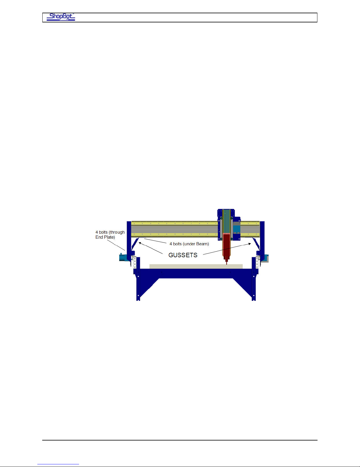
Squaring and Adjusting the X-Car Page -4-
Making an Adjustment for Wheel Bearing Alignment or
Square
The X-Car of your PRS ShopBot is the primary structural component of the tool. We build
the X-Car in a precision fixture that exactly spaces the wheel bearings and that assures a
perfectly square and true gantry. After assembly, we handle and pack the gantry in a way
that is intended to assure it stays square. However, we recognize that in the process of
trucking the tool to your location, considerable stresses can be put on it and that a small
amount of on-site adjustment could be necessary. The following is a general procedure for
dealing with a wheel bearing that rides high or to one side, or with finding that in its relaxed
condition the X-Car is more than the 1/8” out of square (see above for discussion of relaxed
vs powered alignment).
First, make sure that if you are experiencing a problem with the ‘ride’ of one of the wheel
bearings or with square, you have ruled out problems with the rails not being parallel. Make
sure the rails are level. Then test the ride of the wheel bearings up and down the rails and
re-measure the spacing of the rails. If the rail spacing is right, and you have the same ‘ride’
problem up and down the axis, then proceed to make the following adjustment.
Use clamps to lock the X-Car in position. This will take 4 clamps, one at the front and back
of each End Plate of the car. If the car is square, the clamps will keep it locked square.
The Gussets under the beam are designed to define the orientation and position of the end
plates. You’ll loosen them to correct the orientation. There are 4 bolts on the Gusset at the
End Plate and 6 bolts on under the beam. Make sure all bolts are loose. The ones under the
beam sometimes bind after you loosen one of the others, so keep going around and make
sure all are free, but try not to let them come out of the t-nuts in the beam.
For the situation where you are adjusting a wheel: with Gussets loose, if the wheel bearing
has not dropped onto the rail, give the End Plate a downward tap with a rubber mallet to
get the wheel bearing into position.
For the situation where you are adjusting square: with Gussets loose, use the clamps to
move one side of the car the distance required to make it square, and check to see that all
the wheels are correctly re-seat themselves, a tap with a rubber mallet may be necessary.
Now you are ready to re-tighten the Gussets. First, tighten the lower 4 bolts on each
Gusset, then draw up the 6 top bolts tightening each a little at a time.
SquaringXCar080916 Copyright 2008 ShopBot Tools, Inc
Page 83

Table Drawings
PRS Table Drawings
ShopBot Tools, Inc
3333B Industrial Dr
Durham, NC 27704
919-680-4800 or 888-680-4466
www.shopbottools.com
TablePlansCover.doc Copyright 2007 ShopBot Tools, Inc
Page 84
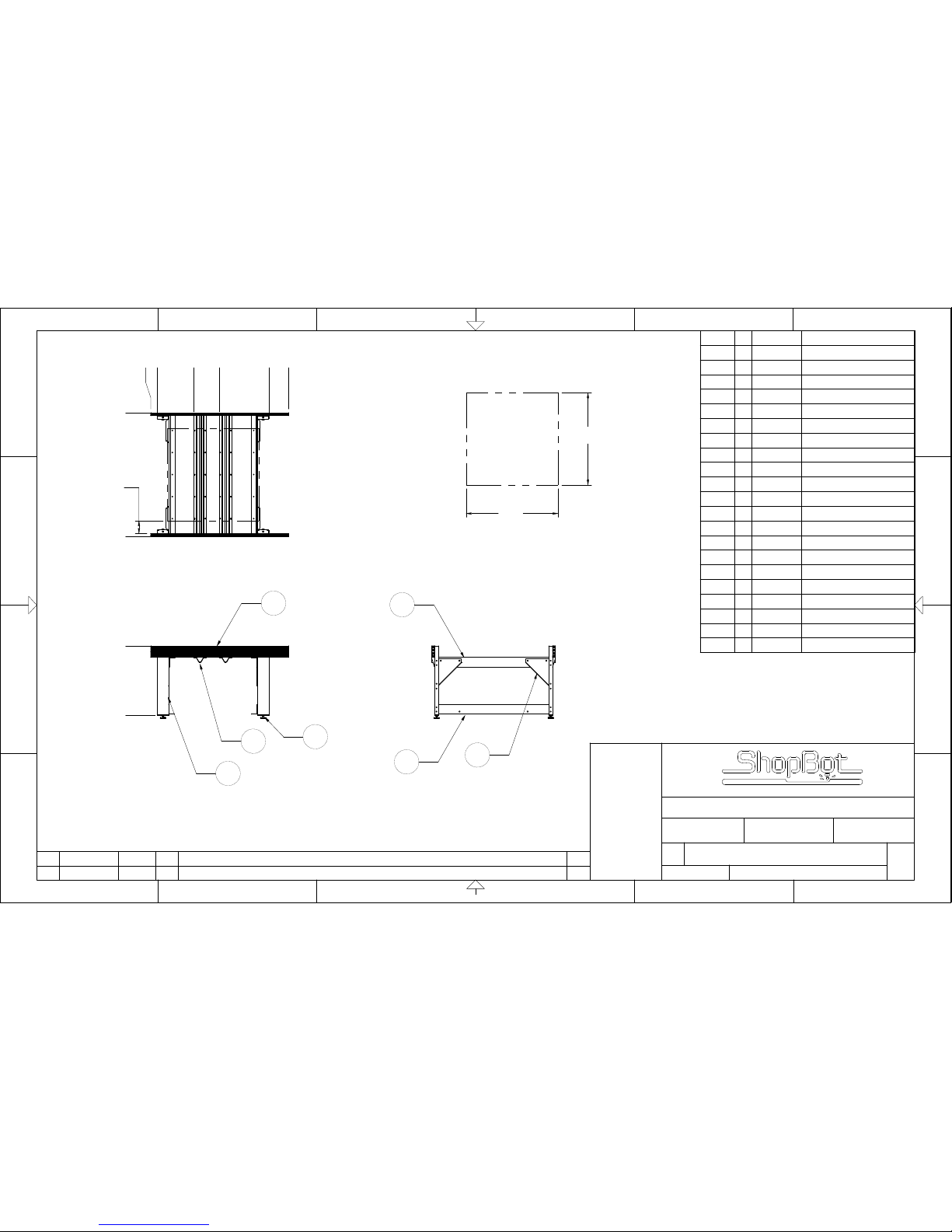
.000
36.250
2
6
7
1
.000
3.375
22.410
35.750
61.625
72.000
.000
64.500
48.0
48.0
6.75
DECK
ONLY
VIEW A
SEE NOTE 2
4
3
5
Item No. Qty Part Number Description
1 2 000923-01 TABLE SIDE 48E
2 4 000919-01 TABLE LEG 6E
3 4 000770-01 TABLE GUSSET
4 2 000915-01 TABLE SUPPORT UPPER 48E
5 2 000921-01 TABLE SUPPORT LOWER 48E
6 2 000926-01 TABLE SUPPORT CROSS 48E
7 4 000661-01 MACHINE GLIDE
8 4 000160-01 NUT HEX 5/8-11 Z5
9 4 000845-01 WASHER LOCK 5/8 Z
10 48 000727-01 NUT T HEAVY DUTY 5/16-18
11 48 000529-01 HCS 5/16-18 X 3/4 Z5
12 48 000848-01 WASHER FLAT 5/16 Z USS
13 24 001956-01 HCS 1/2-13 X 1 1/2 Z5
14 24 000440-01 NUT HEX 1/2-13 Z
15 48 000029-01 WASHER FLAT 1/2 USS Z
16 24 000588-01 WASHER LOCK 1/2 Z
17 24 000953-01 BOLT CARRIAGE 3/8-16 X 1 1/2
18 24 000452-01 NUT HEX 3/8 Z
19 24 000444-01 WASHER FLAT 3/8 USS Z
20 24 000092-01 WASHER LOCK 3/8 Z
21 8 001539-01 TABLE SIDE END CAP
SCALE
SIZE
REV
B
DRAWING NUMBER
PART NUMBER
REV
CHG NOTICE
REVISION DESCRIPTION
10630-00
10630-01
0
06/20/07
DGC
BY
DATE
INITIAL PRODUCTION RELEASE
DGC
06/20/07
0
Durham, North Carolina
TABLE 48-48-8S
DRAWN
CHECKED
DATE
APPROVED
TITLE
APVD
NONE
21
D
C
B
21
©2004, SHOPBOT TOOLS, IN C., ALL RIGHTS RESERVED
3456
3456
AA
D
C
B
THIS DOCUMENT CONTAINS CONFIDENTIAL
INFORMATION OF SHOPBOT TOOLS. IT IS
NOT TO BE REPRODUCED BY ANY MEANS OR
USED TO FURNISH INFORM ATIONTO OTHERS
WITHOUT THE EXPRESS CONSENT TO THE
OWNER. THE INFORMATION SHALL BE USED BY
RECIPIENTS ONLY AS EXPRESSLY APPROVED
BY OWNER AND THIS DOCUMENT SHALL BE
RETURNED TO OWNER UPON REQUEST.
©2004, SH OPBOT TOOLS, INC .,
ALL RIGHTS RESERVED
NOTES:
1. ALL DIMENSIONS ARE IN INCHES.
2. RECOMMENDED SIZE AND ORIENTATION OF
DECK MATERIAL.
Page 85
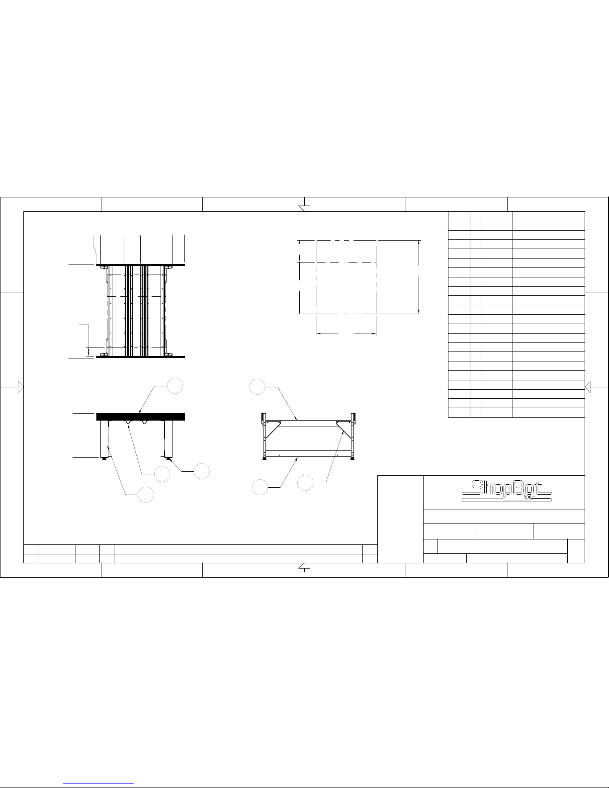
.000
36.250
2
6
7
1
.000
35.750
61.625
3.375
.000
76.500
72.000
22.410
(60.0)
48.0
18.000
42.0
6.75
DECK
ONLY
VIEW A
SEE NOTE 2
4
3
5
Item No. Qty Part Number Description
1 2 000923-01 TABLE SIDE 48E
2 4 000919-01 TABLE LEG 6E
3 4 000770-01 TABLE GUSSET
4 2 001486-01 TABLE SUPPORT UPPER 60E
5 2 001487-01 TABLE SUPPORT LOWER 60E
6 2 001485-01 TABLE SUPPORT CRO SS 60E
7 4 000661-01 MACHINE GLIDE
8 4 000160-01 NUT HEX 5/8-11 Z5
9 4 000845-01 WASHER LOCK 5/8 Z
10 48 000727-01 NUT T HEAVY DUTY 5/16-18
11 48 000529-01 HCS 5/16-18 X 3/4 Z5
12 48 000848-01 WASHER FLAT 5/16 Z USS
13 24 001956-01 HCS 1/2-13 X 1 1/2 Z5
14 24 000440-01 NUT HEX 1/2-13 Z
15 48 000029-01 WASHER FLAT 1/2 USS Z
16 24 000588-01 WASHER LOCK 1/2 Z
17 28 000953-01 BOLT CARRIAGE 3/8-16 X 1 1/2
18 28 000452-01 NUT HEX 3/8 Z
19 28 000444-01 WASHER FLAT 3/8 USS Z
20 28 000092-01 WASHER LOCK 3/8 Z
21 8 001539-01 TABLE SIDE END CAP
SCALE
SIZE
REV
B
DRAWING NUMBER
PART NUMBER
REV
CHG NOTICE
REVISION DESCRIPTION
10631-00
10631-01
0
06/20/07
DGC
BY
DATE
INITIAL PRODUCTION RELEASE
DGC
06/20/07
0
Durham, North Carolina
TABLE 48-60-8S
DRAWN
CHECKED
DATE
APPROVED
TITLE
APVD
NONE
21
D
C
B
21
©2004, SHOPBOT TOOLS, IN C., ALL RIGHTS RESERVED
3456
3456
AA
D
C
B
THIS DOCUMENT CONTAINS CONFIDENTIAL
INFORMATION OF SHOPBOT TOOLS. IT IS
NOT TO BE REPRODUCED BY ANY MEANS OR
USED TO FURNISH INFORM ATIONTO OTHERS
WITHOUT THE EXPRESS CONSENT TO THE
OWNER. THE INFORMATION SHALL BE USED BY
RECIPIENTS ONLY AS EXPRESSLY APPROVED
BY OWNER AND THIS DOCUMENT SHALL BE
RETURNED TO OWNER UPON REQUEST.
©2004, SH OPBOT TOOLS, INC .,
ALL RIGHTS RESERVED
NOTES:
1. ALL DIMENSIONS ARE IN INCHES.
2. RECOMMENDED SIZE AND ORIENTATION
OF DECK MATERIAL.
Page 86
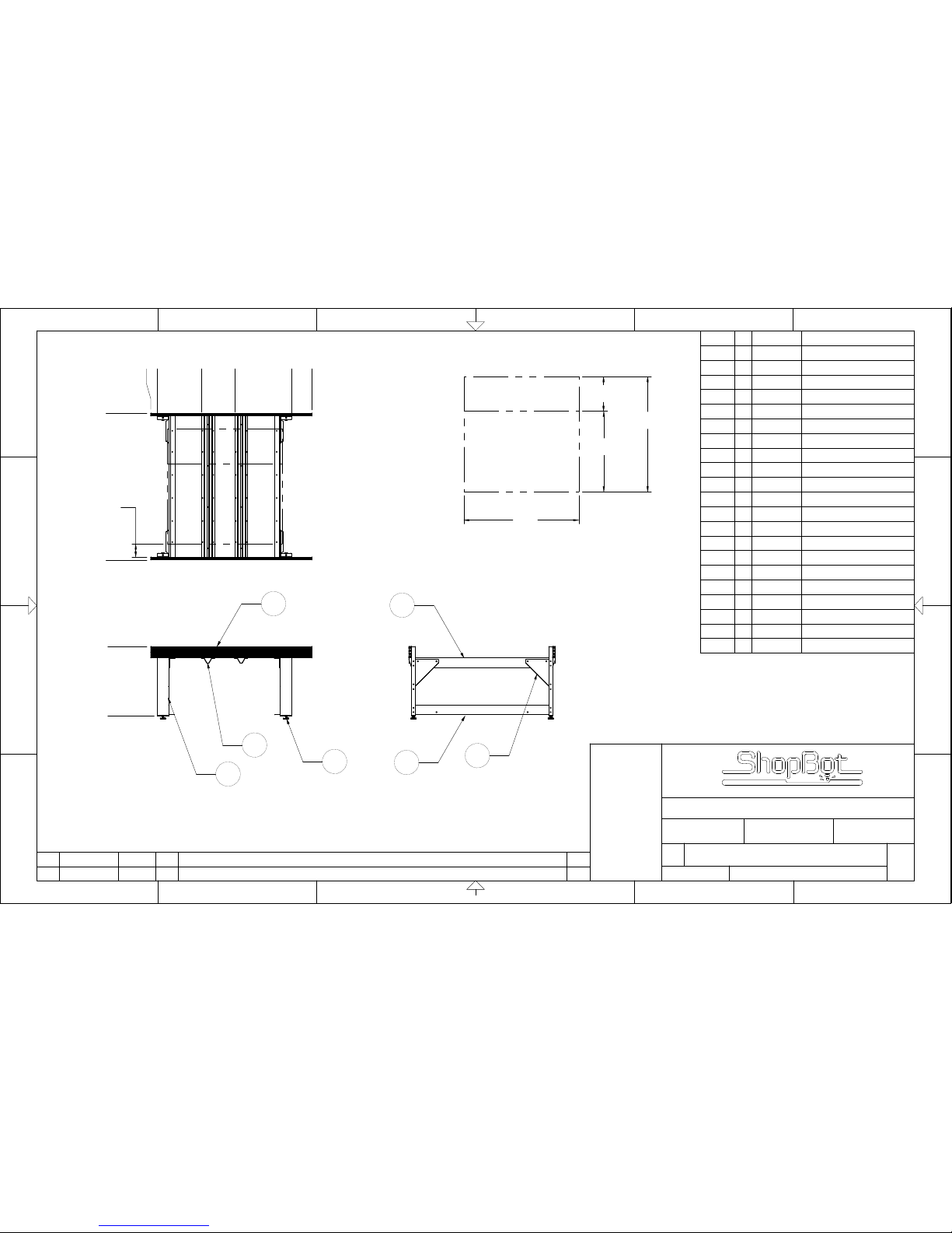
.000
36.250
2
6
7
1
.000
3.375
26.410
43.750
73.625
84.000
.000
76.500
(60.0)
60.0
18.0
42.0
6.75
DECK
ONLY
VIEW A
SEE NOTE 2
4
3
5
Item No. Qty Part Number Description
1 2 000924-01 TABLE SIDE 60E
2 4 000919-01 TABLE LEG 6E
3 4 000770-01 TABLE GUSSET
4 2 001486-01 TABLE SUPPORT UPPER 60E
5 2 001487-01 TABLE SUPPORT LOWER 60E
6 2 001485-01 TABLE SUPPORT CRO SS 60E
7 4 000661-01 MACHINE GLIDE
8 4 000160-01 NUT HEX 5/8-11 Z5
9 4 000845-01 WASHER LOCK 5/8 Z
10 48 000727-01 NUT T HEAVY DUTY 5/16-18
11 48 000529-01 HCS 5/16-18 X 3/4 Z5
12 48 000848-01 WASHER FLAT 5/16 Z USS
13 24 001956-01 HCS 1/2-13 X 1 1/2 Z5
14 24 000440-01 NUT HEX 1/2-13 Z
15 48 000029-01 WASHER FLAT 1/2 USS Z
16 24 000588-01 WASHER LOCK 1/2 Z
17 28 000953-01 BOLT CARRIAGE 3/8-16 X 1 1/2
18 28 000452-01 NUT HEX 3/8 Z
19 28 000444-01 WASHER FLAT 3/8 USS Z
20 28 000092-01 WASHER LOCK 3/8 Z
21 8 001539-01 TABLE SIDE END CAP
SCALE
SIZE
REV
B
DRAWING NUMBER
PART NUMBER
REV
CHG NOTICE
REVISION DESCRIPTION
10634-00
10634-01
0
06/20/07
DGC
BY
DATE
INITIAL PRODUCTION RELEASE
DGC
06/20/07
0
Durham, North Carolina
TABLE 60-60-8S
DRAWN
CHECKED
DATE
APPROVED
TITLE
APVD
NONE
21
D
C
B
21
©2004, SHOPBOT TOOLS, IN C., ALL RIGHTS RESERVED
3456
3456
AA
D
C
B
THIS DOCUMENT CONTAINS CONFIDENTIAL
INFORMATION OF SHOPBOT TOOLS. IT IS
NOT TO BE REPRODUCED BY ANY MEANS OR
USED TO FURNISH INFORM ATIONTO OTHERS
WITHOUT THE EXPRESS CONSENT TO THE
OWNER. THE INFORMATION SHALL BE USED BY
RECIPIENTS ONLY AS EXPRESSLY APPROVED
BY OWNER AND THIS DOCUMENT SHALL BE
RETURNED TO OWNER UPON REQUEST.
©2004, SH OPBOT TOOLS, INC .,
ALL RIGHTS RESERVED
NOTES:
1. ALL DIMENSIONS ARE IN INCHES.
2. RECOMMENDED SIZE AND ORIENTATION
OF DECK MATERIAL.
Page 87
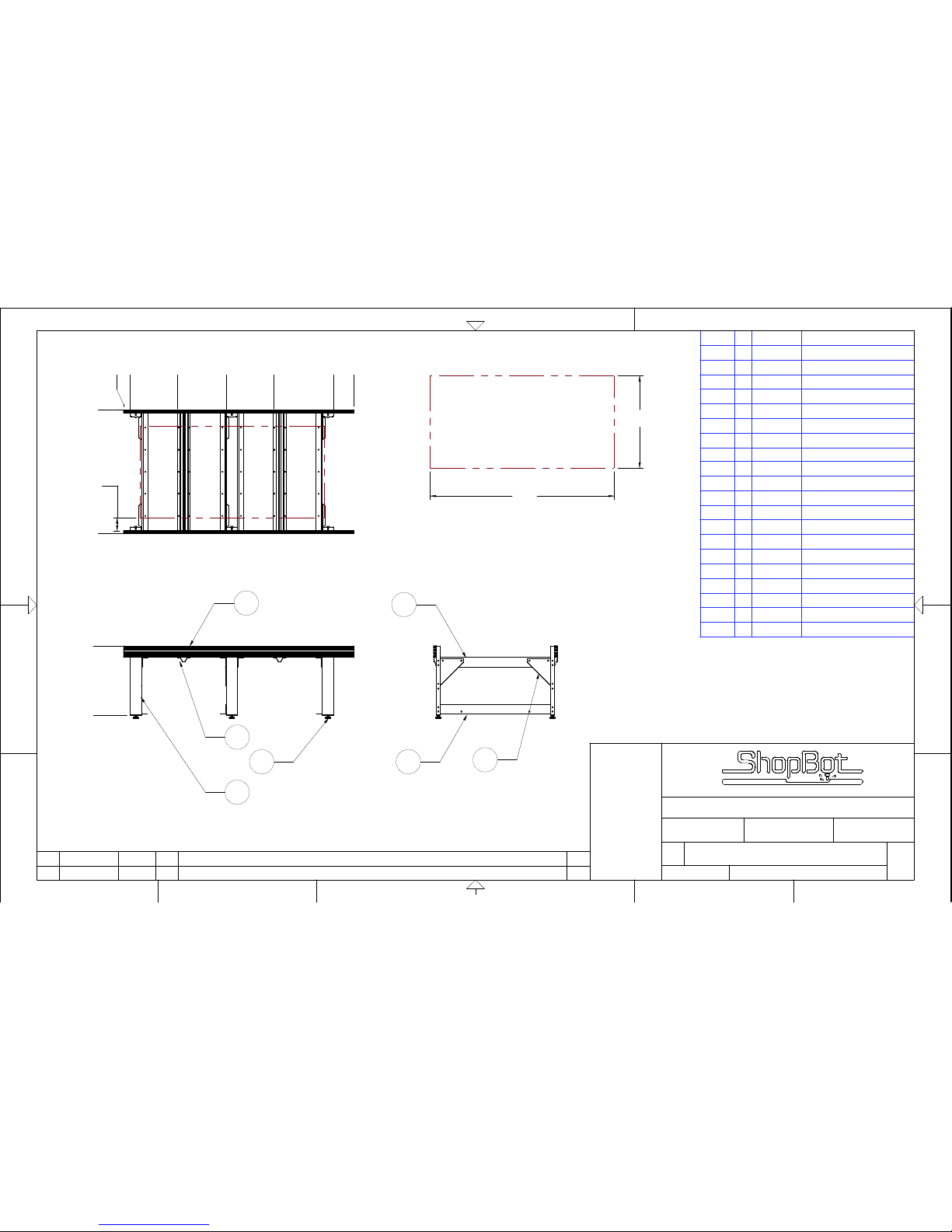
.000
36.250
1
2
6
7
.000
3.375
109.625
120.000
.000
64.500
48.0
96.0
6.75
DECK
ONLY
28.165
53.500
78.111
VIEW A
SEE NOTE 2
4
3
5
Item No. Qty Part Number Description
1 2 000925-01 TABLE SIDE 96E
2 6 000919-01 TABLE LEG 6E
3 6 000770-01 TABLE GUSSET
4 4 000915-01 TABLE SUPPORT UPPER 48E
5 3 000921-01 TABLE SUPPORT LOWER 48E
6 2 000926-01 TABLE SUPPORT CROSS 48E
7 6 000661-01 MACHINE GLIDE
8 6 000160-01 NUT HEX 5/8-11 Z5
10 72 000727-01 NUT T HEAVY DUTY 5/16-18
11 72 000529-01 HCS 5/16-18 X 3/4 Z5
12 72 000848-01 WASHER FLAT 5/16 Z USS
13 40 000589-01 HCS 1/2-13 X 1 1/2 Z5
14 40 000440-01 NUT HEX 1/2-13 Z
15 80 000029-01 WASHER FLAT 1/2 USS Z
16 40 000588-01 WASHER LOCK 1/2 Z
17 40 000953-01
BOLT CARRIAGE 3/8-16 X 1 1/2
18 40 000452-01 NUT HEX 3/8 Z
19 40 000444-01 WASHER FLAT 3/8 USS Z
20 40 000092-01 WASHER LOCK 3/8 Z
21 8 001539-01 TABLE SIDE END CAP
6
SCALE
10632-00
CHG NOTICE
1
©2004 , SH OPBOT TO OLS, I NC., A LL RI GHTS RES ERV ED
JLK
D
PART NUMBER
1
BY
DGC
2
TITLE
C
B
APPROVED
3
B
6
REVISION DESCRIPTION
SIZE
DRAWN
4
CHECKED
5
5/12/09
TABLE 96-48-8S
2
APVD
THIS DO CUM ENT C ONTAIN S CONF IDENTIAL
INFORM ATION OF SHOPBOT TOOLS. IT IS
NOT TO BE REPROD UCED BY ANY MEAN S OR
USED TO FURN ISH INF ORMATIONTO OT HERS
WITHOUT THE EXPRESS CONSENT TO THE
OWNER. TH E INFOR MATION SHALL BE USED BY
RECIPIENT S ONLY AS EXPRESSLY APPRO VED
BY OWNER AND THIS D OCUM ENT SH ALL BE
RETUR NED TO OWNER UPON RE QUEST.
©2004, SHOPBOT TOOLS, INC.,
ALL RIGHTS RESERVED
A
06/20/07
Durham, North Carolina
4
NONE
1
A
5
B
DATE
D
REV
REV
DATE
DRAWIN G NUM BER
3
ECO #198
C
ADDED CENTER LEG
10632-01
1
NOTES:
1. ALL DIMENSIONS ARE IN INCHES.
2. RECOMMENDED SIZE AND ORIENTATION
OF DECK MATERIAL.
Page 88
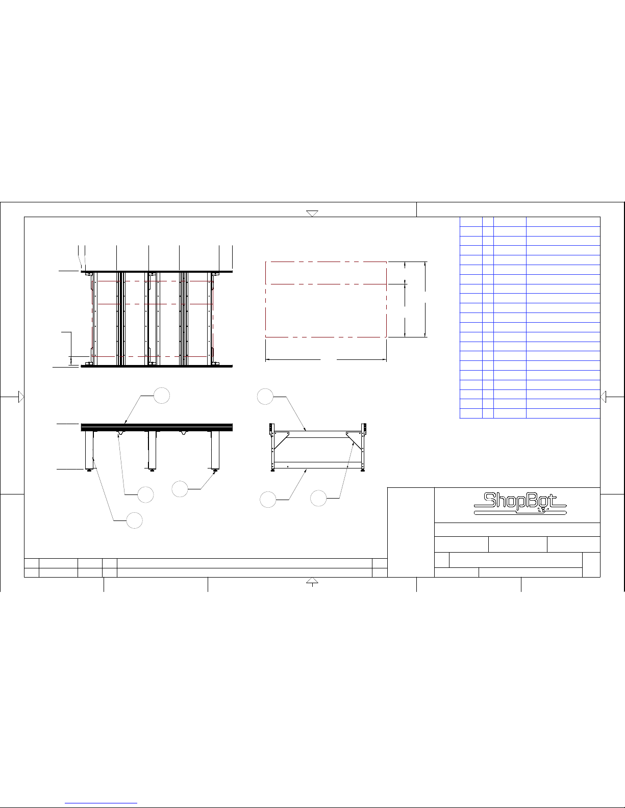
.000
36.250
1
2
6
7
.000
3.375
109.625
120.000
.000
76.500
(60.0)
96.0
18.0
42.0
6.75
DECK
ONLY
28.015
53.500
78.042
VIEW A
SEE NOTE 2
4
3
5
Item No. Qty Part Number Description
1 2 000925-01 TABLE SIDE 96E
2 6 000919-01 TABLE LEG 6E
3 6 000770-01 TABLE GUSSET
4 4 001486-01 TABLE SUPPORT UPPER 60E
5 3 001487-01 TABLE SUPPORT LOWER 60E
6 2 001485-01 TABLE SUPPORT CROSS 60E
7 6 000661-01 MACHINE GLIDE
8 6 000160-01 NUT HEX 5/8-11 Z5
10 72 000727-01 NUT T HEAVY DUTY 5/16-18
11 72 000529-01 HCS 5/16-18 X 3/4 Z5
12 72 000848-01 WASHER FLAT 5/16 Z USS
13 40 000589-01 HCS 1/2-13 X 1 1/2 Z5
14 40 000440-01 NUT HEX 1/2-13 Z
15 80 000029-01 WASHER FLAT 1/2 USS Z
16 40 000588-01 WASHER LOCK 1/2 Z
17 48 000953-01
BOLT CARRIAGE 3/8-16 X 1 1/2
18 48 000452-01 NUT HEX 3/8 Z
19 48 000444-01 WASHER FLAT 3/8 USS Z
20 48 000092-01 WASHER LOCK 3/8 Z
21 8 001539-01 TABLE SIDE END CAP
5
4
ECO #198
NONE
REV
DRAWIN G NUM BER
BY
B
6
REV
5
APVD
C
JLK
C
DGC
5/12/09
10633-00
1
APPROVED
TABLE 96-60-8S
2
THIS DO CUM ENT C ONTAIN S CONF IDENTIAL
INFORM ATION OF SHOPBOT TOOLS. IT IS
NOT TO BE REPROD UCED BY ANY MEAN S OR
USED TO FURN ISH INF ORMATIONTO OT HERS
WITHOUT THE EXPRESS CONSENT TO THE
OWNER. TH E INFOR MATION SHALL BE USED BY
RECIPIENT S ONLY AS EXPRESSLY APPRO VED
BY OWNER AND THIS D OCUM ENT SH ALL BE
RETUR NED TO OWNER UPON RE QUEST.
©2004, SHOPBOT TOOLS, INC.,
ALL RIGHTS RESERVED
ADDED CENTER LEG
REVISION DESCRIPTION
B
A
1
SCALE
10633-01
©2004 , SH OPBOT TO OLS, I NC., A LL RI GHTS RES ERV ED
3
B
4
D
SIZE
D
Durham, North Carolina
2
A
DRAWN
CHECKED
TITLE
1
6
06/20/07
DATE
CHG NOTICE
1
PART NUMBER
3
DATE
NOTES:
1. ALL DIMENSIONS ARE IN INCHES.
2. RECOMMENDED SIZE AND ORIENTATION
OF DECK MATERIAL.
Page 89
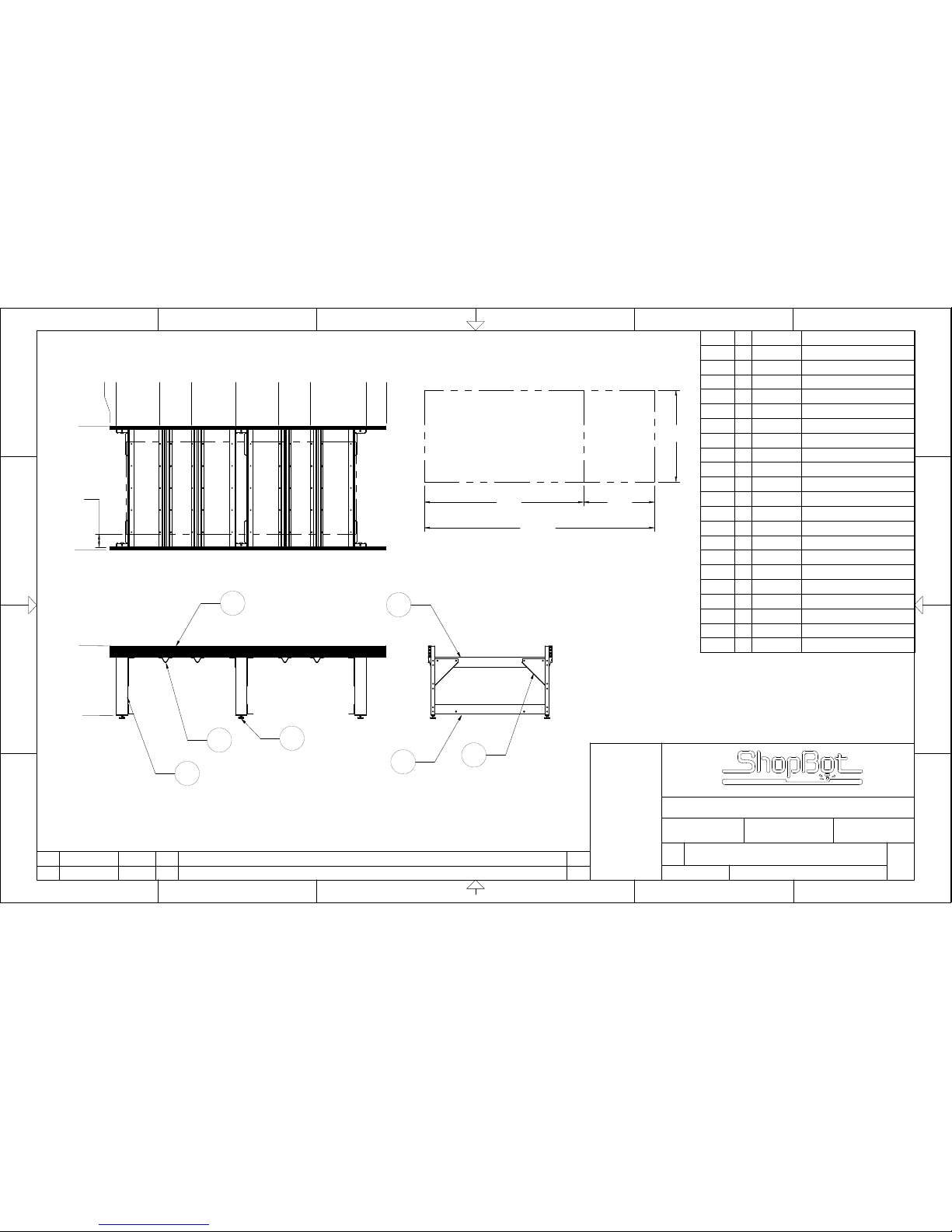
.000
36.250
2
6
7
1
.000
3.375
25.740
42.410
65.500
87.745
104.415
133.625
144.000
.000
64.500
48.0
(120.0)
83.0 37.0
6.75
DECK
ONLY
VIEW A
SEE NOTE 2
4
3
5
Item No. Qty Part Number Description
1 2 001550-01 TABLE SIDE 120E
2 6 000919-01 TABLE LEG 6E
3 6 000770-01 TABLE GUSSET
4 4 000915-01 TABLE SUPPORT UPPER 48E
5 3 000921-01 TABLE SUPPORT LOWER 48E
6 4 000926-01 TABLE SUPPORT CRO SS 48E
7 6 000661-01 MACHINE GLIDE
8 6 000160-01 NUT HEX 5/8-11 Z5
9 6 000845-01 WASHER LOCK 5/8 Z
10 80 000727-01 NUT T HEAVY DUTY 5/16-18
11 80 000529-01 HCS 5/16-18 X 3/4 Z5
12 80 000848-01 WASHER FLAT 5/16 Z USS
13 40 001956-01 HCS 1/2-13 X 1 1/2 Z5
14 40 000440-01 NUT HEX 1/2-13 Z
15 80 000029-01 WASHER FLAT 1/2 USS Z
16 40 000588-01 WASHER LOCK 1/2 Z
17 52 000953-01 BOLT CARRIAGE 3/8-16 X 1 1/2
18 52 000452-01 NUT HEX 3/8 Z
19 52 000444-01 WASHER FLAT 3/8 USS Z
20 52 000092-01 WASHER LOCK 3/8 Z
21 8 001539-01 TABLE SIDE END CAP
SCALE
SIZE
REV
B
DRAWING NUMBER
PART NUMBER
REV
CHG NOTICE
REVISION DESCRIPTION
10635-00
10635-01
0
06/20/07
DGC
BY
DATE
INITIAL PRODUCTION RELEASE
DGC
06/20/07
0
Durham, North Carolina
TABLE 120-48-8S
DRAWN
CHECKED
DATE
APPROVED
TITLE
APVD
NONE
21
D
C
B
21
©2004, SHOPBOT TOOLS, IN C., ALL RIGHTS RESERVED
3456
3456
AA
D
C
B
THIS DOCUMENT CONTAINS CONFIDENTIAL
INFORMATION OF SHOPBOT TOOLS. IT IS
NOT TO BE REPRODUCED BY ANY MEANS OR
USED TO FURNISH INFORM ATIONTO OTHERS
WITHOUT THE EXPRESS CONSENT TO THE
OWNER. THE INFORMATION SHALL BE USED BY
RECIPIENTS ONLY AS EXPRESSLY APPROVED
BY OWNER AND THIS DOCUMENT SHALL BE
RETURNED TO OWNER UPON REQUEST.
©2004, SH OPBOT TOOLS, INC .,
ALL RIGHTS RESERVED
NOTES:
1. ALL DIMENSIONS ARE IN INCHES.
2. RECOMMENDED SIZE AND ORIENTATION
OF DECK MATERIAL.
Page 90
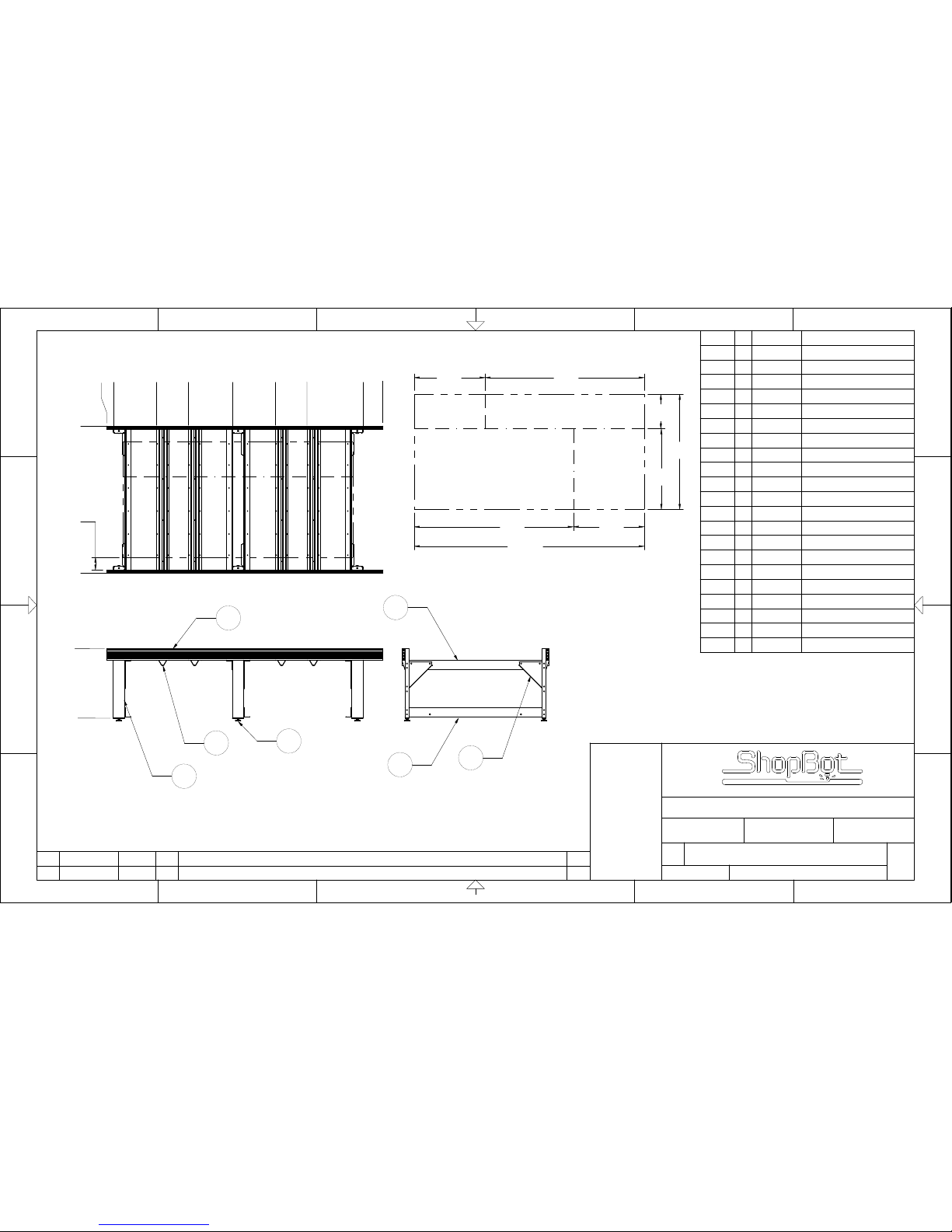
.000
36.250
2
6
7
1
.000
3.375
25.740
42.410
65.500
87.745
133.625
104.415
144.000
.000
76.500
(60.0)
(120.0)
83.0
18.0
42.0
83.0
37.0
37.0
6.75
DECK
ONLY
VIEW A
SEE NOTE 2
4
3
5
Item No. Qty Part Number Description
1 2 001550-01 TABLE SIDE 120E
2 6 000919-01 TABLE LEG 6E
3 6 000770-01 TABLE GUSSET
4 4 001486-01 TABLE SUPPORT UPPER 60E
5 3 001487-01 TABLE SUPPORT LOWER 60E
6 4 001485-01 TABLE SUPPORT CRO SS 60E
7 6 000661-01 MACHINE GLIDE
8 6 000160-01 NUT HEX 5/8-11 Z5
9 6 000845-01 WASHER LOCK 5/8 Z
10 80 000727-01 NUT T HEAVY DUTY 5/16-18
11 80 000529-01 HCS 5/16-18 X 3/4 Z5
12 80 000848-01 WASHER FLAT 5/16 Z USS
13 40 001956-01 HCS 1/2-13 X 1 1/2 Z5
14 40 000440-01 NUT HEX 1/2-13 Z
15 80 000029-01 WASHER FLAT 1/2 USS Z
16 40 000588-01 WASHER LOCK 1/2 Z
17 56 000953-01 BOLT CARRIAGE 3/8-16 X 1 1/2
18 56 000452-01 NUT HEX 3/8 Z
19 56 000444-01 WASHER FLAT 3/8 USS Z
20 56 000092-01 WASHER LOCK 3/8 Z
21 8 001539-01 TABLE SIDE END CAP
SCALE
SIZE
REV
B
DRAWING NUMBER
PART NUMBER
REV
CHG NOTICE
REVISION DESCRIPTION
10636-00
10636-01
0
06/20/07
DGC
BY
DATE
INITIAL PRODUCTION RELEASE
DGC
06/20/07
0
Durham, North Carolina
TABLE 120-60-8S
DRAWN
CHECKED
DATE
APPROVED
TITLE
APVD
NONE
21
D
C
B
21
©2004, SHOPBOT TOOLS, IN C., ALL RIGHTS RESERVED
3456
3456
AA
D
C
B
THIS DOCUMENT CONTAINS CONFIDENTIAL
INFORMATION OF SHOPBOT TOOLS. IT IS
NOT TO BE REPRODUCED BY ANY MEANS OR
USED TO FURNISH INFORM ATIONTO OTHERS
WITHOUT THE EXPRESS CONSENT TO THE
OWNER. THE INFORMATION SHALL BE USED BY
RECIPIENTS ONLY AS EXPRESSLY APPROVED
BY OWNER AND THIS DOCUMENT SHALL BE
RETURNED TO OWNER UPON REQUEST.
©2004, SH OPBOT TOOLS, INC .,
ALL RIGHTS RESERVED
NOTES:
1. ALL DIMENSIONS ARE IN INCHES.
2. RECOMMENDED SIZE AND ORIENTATION
OF DECK MATERIAL.
Page 91
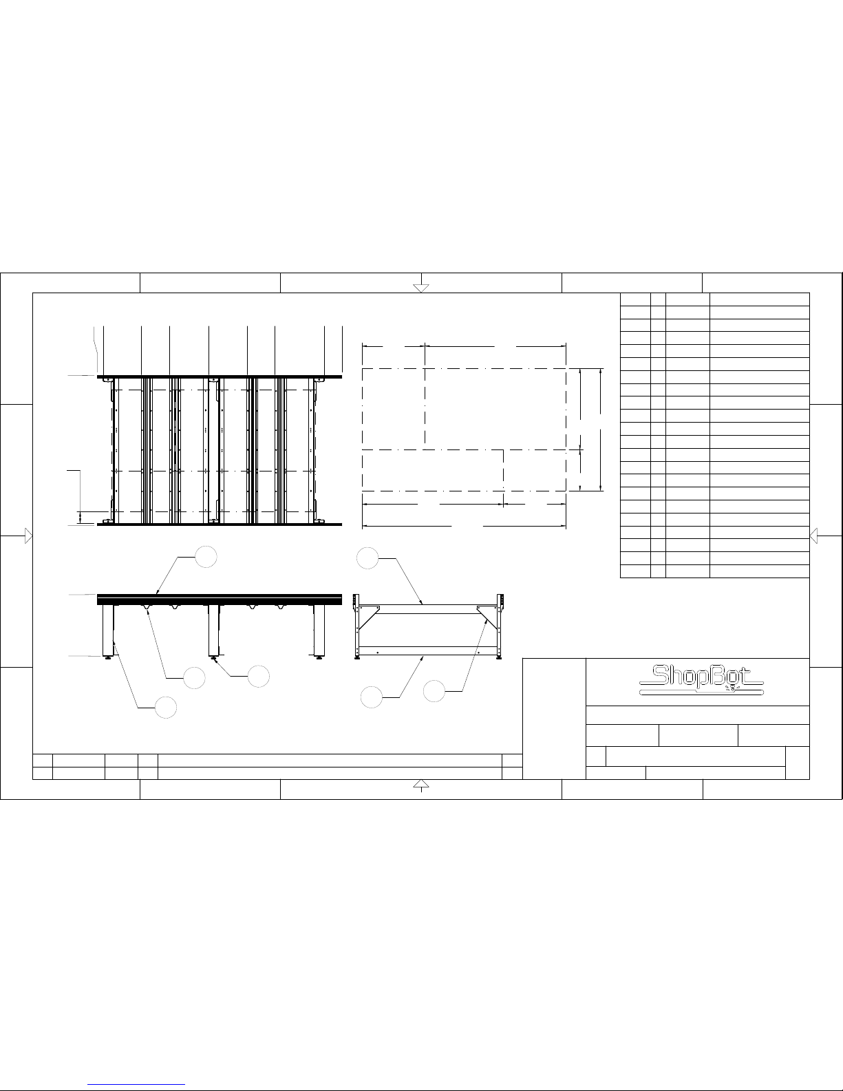
.000
36.250
2
7
1
6
.000
88.500
.000
3.375
25.740
42.410
65.500
88.045
104.415
133.625
144.000
(72.0)
(120.0)
83.0
83.0
37.0
24.0
48.0
37.0
6.75
DECK
ONLY
VIEW A
SEE NOTE 2
3
4
5
Item No. Qty Part Number Description
1 2 001550-01 TABLE SIDE 120E
2 6 000919-01 TABLE LEG 6E
3 6 000770-01 TABLE GUSSET
4 4 001881-01 TABLE SUPPORT UPPER 72E
5 3 001882-01 TABLE SUPPORT LOWER 72E
6 4 001880-01 TABLE SUPPORT CRO SS 72E
7 6 000661-01 MACHINE GLIDE
8 6 000160-01 NUT HEX 5/8-11 Z5
9 6 000845-01 WASHER LOCK 5/8 Z
10 80 000727-01 NUT T HEAVY DUTY 5/16-18
11 80 000529-01 HCS 5/16-18 X 3/4 Z5
12 80 000848-01 WASHER FLAT 5/16 Z USS
13 40 001956-01 HCS 1/2-13 X 1 1/2 Z5
14 40 000440-01 NUT HEX 1/2-13 Z
15 80 000029-01 WASHER FLAT 1/2 USS Z
16 40 000588-01 WASHER LOCK 1/2 Z
17 56 000953-01 BOLT CARRIAGE 3/8-16 X 1 1/2
18 56 000452-01 NUT HEX 3/8 Z
19 56 000444-01 WASHER FLAT 3/8 USS Z
20 56 000092-01 WASHER LOCK 3/8 Z
21 8 001539-01 TABLE SIDE END CAP
SCALE
SIZE
REV
B
DRAWING NUMBER
PART NUMBER
REV
CHG NOTICE
REVISION DESCRIPTION
10625-00
10625-01
0
03/02/07
DGC
BY
DATE
INITIAL PRODUCTION RELEASE
DGC
05/08/07
0
Durham, North Carolina
TABLE 120-72-8S
DRAWN
CHECKED
DATE
APPROVED
TITLE
APVD
NONE
21
D
C
B
21
©2004, SHOPBOT TOOLS, IN C., ALL RIGHTS RESERVED
3456
3456
AA
D
C
B
THIS DOCUMENT CONTAINS CONFIDENTIAL
INFORMATION OF SHOPBOT TOOLS. IT IS
NOT TO BE REPRODUCED BY ANY MEANS OR
USED TO FURNISH INFORM ATIONTO OTHERS
WITHOUT THE EXPRESS CONSENT TO THE
OWNER. THE INFORMATION SHALL BE USED BY
RECIPIENTS ONLY AS EXPRESSLY APPROVED
BY OWNER AND THIS DOCUMENT SHALL BE
RETURNED TO OWNER UPON REQUEST.
©2004, SH OPBOT TOOLS, INC .,
ALL RIGHTS RESERVED
NOTES:
1. ALL DIMENSIONS ARE IN INCHES.
2. RECOMMENDED SIZE AND ORIENTATION
OF DECK MATERIAL.
Page 92
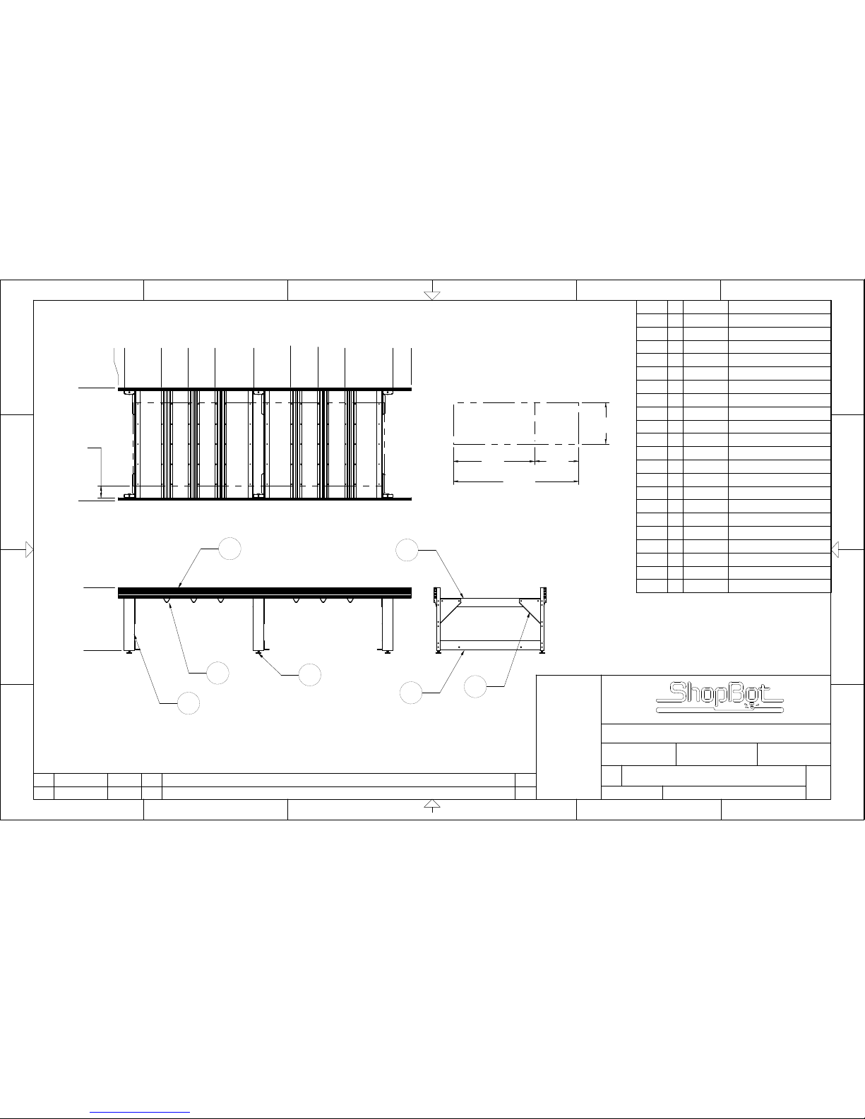
.000
36.250
2
6
7
1
.000
3.375
24.571
40.073
55.575
77.500
98.880
114.382
129.884
157.625
168.000
.000
64.500
48.0
(144.0)
93.0
51.0
6.75
DECK
ONLY
VIEW A
SEE NOTE 2
4
3
5
Item No. Qty Part Number Description
1 2 001581-01 TABLE SIDE 144E
2 6 000919-01 TABLE LEG 6E
3 6 000770-01 TABLE GUSSET
4 4 000915-01 TABLE SUPPORT UPPER 48E
5 3 000921-01 TABLE SUPPORT LOWER 48E
6 6 000926-01 TABLE SUPPORT CRO SS 48E
7 6 000661-01 MACHINE GLIDE
8 6 000160-01 NUT HEX 5/8-11 Z5
9 6 000845-01 WASHER LOCK 5/8 Z
10 88 000727-01 NUT T HEAVY DUTY 5/16-18
11 88 000529-01 HCS 5/16-18 X 3/4 Z5
12 88 000848-01 WASHER FLAT 5/16 Z USS
13 40 001956-01 HCS 1/2-13 X 1 1/2 Z5
14 40 000440-01 NUT HEX 1/2-13 Z
15 80 000029-01 WASHER FLAT 1/2 USS Z
16 40 000588-01 WASHER LOCK 1/2 Z
17 62 000953-01 BOLT CARRIAGE 3/8-16 X 1 1/2
18 62 000452-01 NUT HEX 3/8 Z
19 62 000444-01 WASHER FLAT 3/8 USS Z
20 62 000092-01 WASHER LOCK 3/8 Z
21 8 001539-01 TABLE SIDE END CAP
SCALE
SIZE
REV
B
DRAWING NUMBER
PART NUMBER
REV
CHG NOTICE
REVISION DESCRIPTION
10637-00
10637-01
0
06/20/07
DGC
BY
DATE
INITIAL PRODUCTION RELEASE
DGC
06/20/07
0
Durham, North Carolina
TABLE 144-48-8S
DRAWN
CHECKED
DATE
APPROVED
TITLE
APVD
NONE
21
D
C
B
21
©2004, SHOPBOT TOOLS, IN C., ALL RIGHTS RESERVED
3456
3456
AA
D
C
B
THIS DOCUMENT CONTAINS CONFIDENTIAL
INFORMATION OF SHOPBOT TOOLS. IT IS
NOT TO BE REPRODUCED BY ANY MEANS OR
USED TO FURNISH INFORM ATIONTO OTHERS
WITHOUT THE EXPRESS CONSENT TO THE
OWNER. THE INFORMATION SHALL BE USED BY
RECIPIENTS ONLY AS EXPRESSLY APPROVED
BY OWNER AND THIS DOCUMENT SHALL BE
RETURNED TO OWNER UPON REQUEST.
©2004, SH OPBOT TOOLS, INC .,
ALL RIGHTS RESERVED
NOTES:
1. ALL DIMENSIONS ARE IN INCHES.
2. RECOMMENDED SIZE AND ORIENTATION
OF DECK MATERIAL.
Page 93
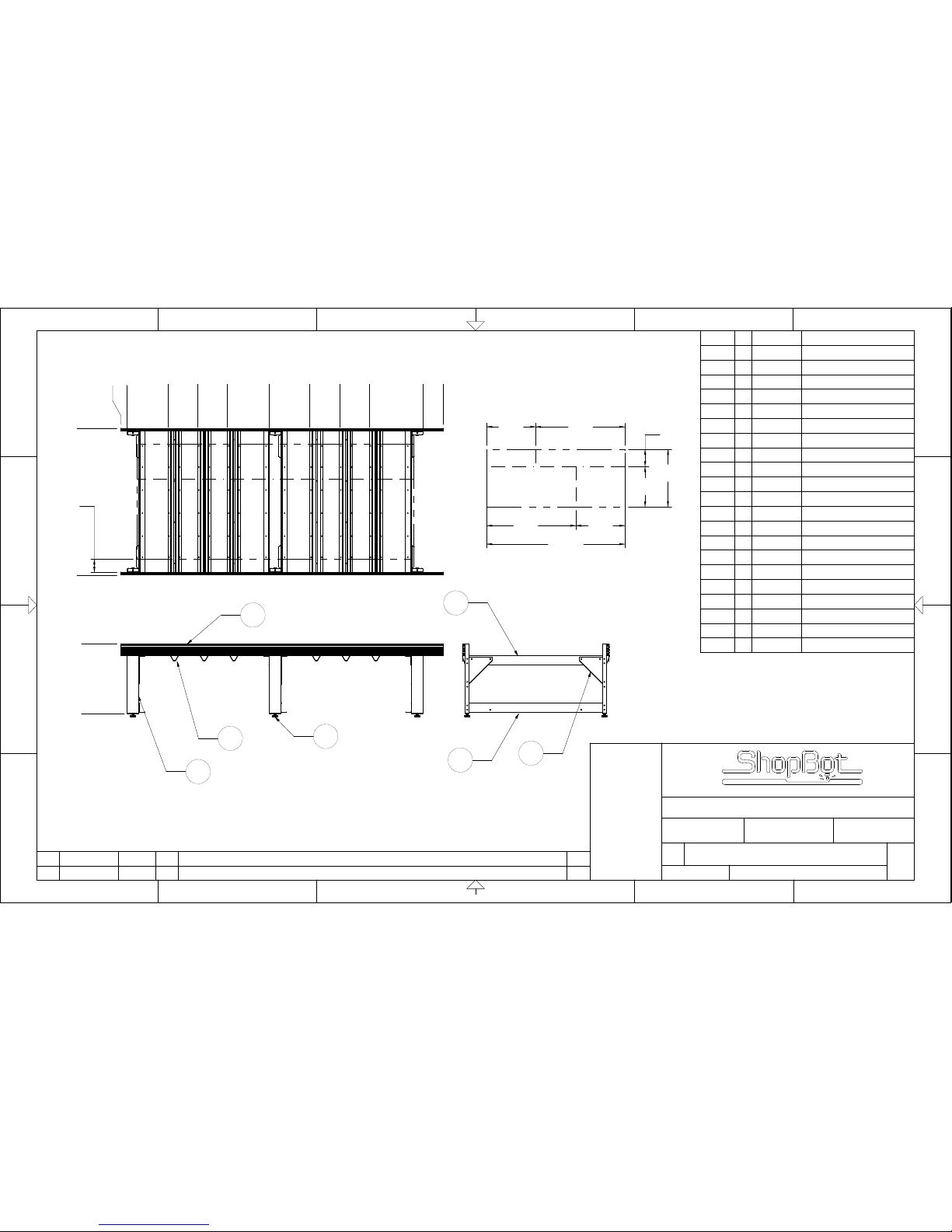
.000
36.250
2
6
7
1
.000
24.571
40.073
55.575
77.500
98.580
114.082
129.584
157.625
168.000
.000
76.500
3.375
(144.0)
(60.0)
93.0
93.0
18.0
51.0
51.0
42.0
6.75
DECK
ONLY
VIEW A
SEE NOTE 2
4
3
5
Item No. Qty Part Number Description
1 2 001581-01 TABLE SIDE 144E
2 6 000919-01 TABLE LEG 6E
3 6 000770-01 TABLE GUSSET
4 4 001486-01 TABLE SUPPORT UPPER 60E
5 3 001487-01 TABLE SUPPORT LOWER 60E
6 6 001485-01 TABLE SUPPORT CRO SS 60E
7 6 000661-01 MACHINE GLIDE
8 6 000160-01 NUT HEX 5/8-11 Z5
9 6 000845-01 WASHER LOCK 5/8 Z
10 88 000727-01 NUT T HEAVY DUTY 5/16-18
11 88 000529-01 HCS 5/16-18 X 3/4 Z5
12 88 000848-01 WASHER FLAT 5/16 Z USS
13 40 001956-01 HCS 1/2-13 X 1 1/2 Z5
14 40 000440-01 NUT HEX 1/2-13 Z
15 80 000029-01 WASHER FLAT 1/2 USS Z
16 40 000588-01 WASHER LOCK 1/2 Z
17 72 000953-01 BOLT CARRIAGE 3/8-16 X 1 1/2
18 72 000452-01 NUT HEX 3/8 Z
19 72 000444-01 WASHER FLAT 3/8 USS Z
20 72 000092-01 WASHER LOCK 3/8 Z
21 8 001539-01 TABLE SIDE END CAP
SCALE
SIZE
REV
B
DRAWING NUMBER
PART NUMBER
REV
CHG NOTICE
REVISION DESCRIPTION
10638-00
10638-01
0
06/20/07
DGC
BY
DATE
INITIAL PRODUCTION RELEASE
DGC
06/20/07
0
Durham, North Carolina
TABLE 144-60-8S
DRAWN
CHECKED
DATE
APPROVED
TITLE
APVD
NONE
21
D
C
B
21
©2004, SHOPBOT TOOLS, IN C., ALL RIGHTS RESERVED
3456
3456
AA
D
C
B
THIS DOCUMENT CONTAINS CONFIDENTIAL
INFORMATION OF SHOPBOT TOOLS. IT IS
NOT TO BE REPRODUCED BY ANY MEANS OR
USED TO FURNISH INFORM ATIONTO OTHERS
WITHOUT THE EXPRESS CONSENT TO THE
OWNER. THE INFORMATION SHALL BE USED BY
RECIPIENTS ONLY AS EXPRESSLY APPROVED
BY OWNER AND THIS DOCUMENT SHALL BE
RETURNED TO OWNER UPON REQUEST.
©2004, SH OPBOT TOOLS, INC .,
ALL RIGHTS RESERVED
NOTES:
1. ALL DIMENSIONS ARE IN INCHES.
2. RECOMMENDED SIZE AND ORIENTATION
OF DECK MATERIAL.
 Loading...