

Page 1

OPERATOR’S MANUAL
Intravascular Lithotripsy (IVL)
Generator and Connector Cable
LBL 61876 Rev E / Revision Date: March 2018
Contents
1.
Introduction ............................................................................................................................................................ 2
1.1 The IVL Generator - How Supplied .................................................................................................................................................................. 2
1.2 Required Devices and Procedure Supplies for Use with the IVL Generator .............................................................................................................. 2
1.3 Device Description ....................................................................................................................................................................................... 2
1.4 Intended Use/In dication for Use ..................................................................................................................................................................... 2
2. Safety Information .................................................................................................................................................. 2
2.1 Terms ........................................................................................................................................................................................................ 2
2.2 Contraindications ......................................................................................................................................................................................... 2
2.3 Dangers ..................................................................................................................................................................................................... 2
2.4 Warnings .................................................................................................................................................................................................... 2
2.5 Cautions ..................................................................................................................................................................................................... 3
3. Product Orientation ................................................................................................................................................. 3
3.1 IVL Generator - Front View ............................................................................................................................................................................ 3
3.2 Control and Indicator Functions ...................................................................................................................................................................... 4
3.3 Front Panel Connectors ................................................................................................................................................................................. 4
3.4 IVL Connector Cable ..................................................................................................................................................................................... 4
3.5 IVL Generator – Rear View ............................................................................................................................................................................ 4
4. Product Use and Therapy Delivery .......................................................................................................................... 5
4.1 Additional Usage Information ......................................................................................................................................................................... 6
5. Installation ............................................................................................................................................................. 7
5.1 IV Pole Mounting .......................................................................................................................................................................................... 7
5.2 Connecting to Line Power .............................................................................................................................................................................. 9
5.3 Charging th e Internal Battery ......................................................................................................................................................................... 9
5.4 Environment Conditioning.............................................................................................................................................................................. 9
5.5 Generator Inspection and Test ....................................................................................................................................................................... 9
6. Maintenance .......................................................................................................................................................... 10
6.1 Daily Maintenance .......................................................................................................................................................................................10
6.1.1 Charging and Testing the Internal Battery .............................................................................................................................................. 10
6.1.2 Testing the IVL Generator .................................................................................................................................................................... 11
6.1.3 Inspecting the IVL Generator ............................................................................................................................................................... 11
6.1.4 Cleaning the IVL Generator .................................................................................................................................................................. 11
6.2 Monthly Maintenance ...................................................................................................................................................................................11
6.3 Other Maintenance ......................................................................................................................................................................................12
6.4 Product Useful Life ......................................................................................................................................................................................12
7. Troubleshooting .................................................................................................................................................... 12
8. Appendix A: Electromagnetic Compatibility Guidance ........................................................................................... 13
9. Appendix B: Symbols ............................................................................................................................................. 14
10. Appendix C: Specifications .................................................................................................................................... 15
10.1 Appendix C1: General Specifications ..............................................................................................................................................................15
10.2 Appendix C2: Performance Specifications ........................................................................................................................................................15
NOTE: This Operator’s Manual provides inf o rm ation required for proper operation of the IVL Generator and IVL Connector Cable. Replacement IVL Connector Cables are
TEXT CONVENTIONS: Throughout these operating instructions, special text characters (for example, CAPITAL LETTERS such as ON, CATH, SYS) are used to indicate
LBL 61876 rev. E, March 2018 EN 1
available from Shockwave Medical, Inc. Refer to the applicable IVL Catheter Instructions for Use (IFU) for patient treatment information.
To Be Used Exclusively with the Shockwave Medical IVL System.
controls, connectors and lighted annunciators.
Page 2
1. Introduction
CAUTION
The IVL System is intended to be used by experienced medical personnel in a catheterization lab within the environmental ranges specified in Appendix C. This device
should only be used following an arteriogram (or CT or MRI) of the vascular system and confirmation of appropriate ta rget lumen size.
DANGER
EXPLOSION HAZARD
WARNINGS
GENERAL WARNINGS
possibly cause harm to the user. Do not autoclave or sterilize the IVL Generator or IVL Connector Cables as this may cause the IVL Generator or IVL Connector Cable to malfunction.
IVL Generator
The Shockwave Medical Intravascular Lithotripsy (IVL) System is comprised of the IVL Generator, IVL Connector Cable and IVL Catheters. The IVL Generator and Connector
Cable are to be used exclusively with the IVL Catheters. The IVL Catheter incorporates unique energy emitting transducers inside the distal balloon. This technology uses
lithotripsy to achieve clinically significant dilation at low balloon pressures.
1.1 The IVL Generator - How Supplied
The IVL Generator is provided non-sterile and is reusable. The IVL Generator is shipped with the follo wing items:
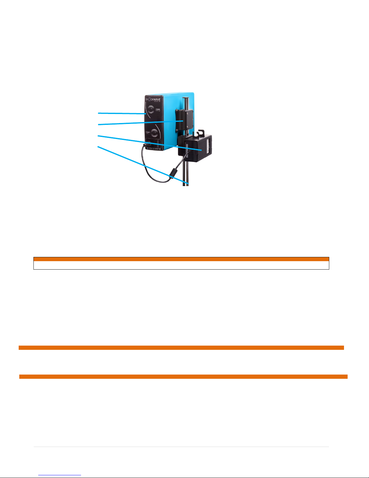
The product is shipped as an assembly including the IVL Generator, IV Pole Mount and C harger Module for mounting on an IV pole, as shown below:
1.2 Required Devices and Procedure Supplies for Use with the IVL Generator
1.3 Device Description
The IVL Generator and Connector Cable are used with a Shockwave Medical IVL Catheter to deliver localized, lithotripsy-enhanced, balloon dilatation of calcified, stenotic
arteries. The IVL Generator, IVL Connector Cable and IVL Catheters are designed to exchange data during patient tre atment. This feature is designed to auto m atically set
pulse parameters unique to each catheter type such as catheter pulse life; refer to the applicable IVL Catheter Instru c tions for Use for addi tional informatio n.
1.4 Intended Use/Indication for Use
The Shockwave Medical IVL Generator and Connector Cable are intended for u se with Shockwave Medical IVL Catheters only.
NOTE: Refer to the individual Shockwave Medical IVL Catheter Instructions for Use. It is important to carefully review the specific indications, contraindications,
• IV Pole Mounts for IVL Generator and Charger
• Charger Module
• 1 ea* IVL Connector Cable (See Section 3.4)
• AC Mains Cable
• Operator’s Manual
* Additional IVL Connector Cables can be ordered separately.
IV Pole Mounting Bracket
Charger Module
IV Pole
• Shockwave Medical IVL Catheter
• Sterile Sleeve, 1.52 m long for IVL Connector Cable
• One IV pole with five casters located in a circular pattern with a diameter of at least 23 inches (5 8 cm), and a pole diamet er of 3/4 to 1 inch (19 mm to 25 mm),
such as the I.V. League Ventilator Stat-Stand™ model 10 59 or equivalent is re quired. An IV pole that is securely affixed to the procedure bed may also be used.
warnings, prec autions, and adverse events included with each IVL Catheter prior to use of the IVL Catheter with the IVL Generator and Connector Cable.
2. Safety Information
2.1 Terms
The following terms are used either in these operating instructions or on the IVL Generator:
DANGER: Immediate hazards that will res ult in serious personal i njury or death.
WARNING: Hazards or unsafe prac tices that may result in serious personal injury or death.
CAUTION: Hazards or unsafe practices that may result in minor personal injury, product damage, or property damage.
2.2 Contraindications
There are no specific contraindications for use of the IVL Generator and Connector Cable. However, users should read and understand the specific indications,
contraindications, warnings, and precautions included with the applicable Shockwave Medical IVL Catheter Instructions For Use (IFU).
NOTE: The contraindications listed in the IVL Catheter IFU also apply to the use of the IVL Generator and Connector Cable. Carefully review the specific indications,
2.3 Dangers
This system generates small electrical sparks during normal operation. Do not use this product in the presence of flammable gases or anesthetics.
FIRE HAZARD
The IVL Generator contains a rechargeable lithium ion battery. Do not disasse mble, puncture, crus h, expose to high temperatures, or incinerate the IVL Generator or bat tery.
2.4 Warnings
Do not operate the IVL System until you have read both the Operator’s Manual and the Instructions for Use provided with the IVL Catheter. An understanding of the features, functions,
indicators and connectors of IVL Generator is a prerequisi te for the proper use of this equi pment and before clinical use. The IVL Generator is only compatible with the Shockwave Medical
IVL Catheters and related access o ries.
SHOCK HAZARD
This product delivers pulses of up to 3000 volts of e le ctrical energy. Unless properly used as described in these operating instructions, this electrical energy may cause serious injury. To
avoid the risk of electrical shock, this equipment must only be connected to a grounded electrical outlet (electrical supply mains with protective earth.) Use with a hospital grade receptacle.
Grounding reliability can only be achieved when connected to an equivalent receptacle marked “hospital use” or “hospital grade”. Only use the Charger Module provided with the IVL
Generator to avoid shock.
SHOCK HAZARD
Do not attempt to service the system. It contains no operator serviceable components and dangerous high voltages may be present. No user modification or servicing of this equipment is
allowed. If any part of this product ap pears damaged, remove from use and contact your Shockwave Medical representative for repair or replacement.
SHOCK OR FIRE HAZARD
Do not immerse any portion of the IVL Generator in water or other fluids. Do not immerse IVL Connector Cables in water or other fluids. Avoid spilling any fluids on the IVL Generator.
Spilled liquids may cause the IVL Generator to perform inaccurately or malfunction. Do not clean with solvents or flammable agents as this may cause damage to the IVL Generator and
contraindications, warnings, precautions, and adverse events included with each IVL Catheter, prior to use of the IVL Catheter with the IVL Generator and
Connector Cable.
LBL 61876 rev. E, March 2018 EN 2
Page 3
CAUTIONS
GENERAL CAUTIONS
Power Status
POSSIBLE FIRE
Use care when operating this device close to oxygen source s (such as bag-valve-mask devices or ventilator tubing). Turn off gas source or move source aw ay from patient during therapy.
ELECTRICAL INTERFERENC E HAZARDS
Equipment operating in close proxi m ity may emit strong electromagnetic or radio frequency interference (RFI) which could affe ct the performance of this device. If use of equipment in close
proximity is necessary, observe the device to verify normal operation in the configuration in which the device will be used. Do not operate the IVL Generator near cauterizers, di ath e rmy
equipment, or other portable and mobile RF communications equipment. Refer to Appendix A for recommended distances of equipment. Contact your Shockwave Medical representative if
assistance is required.
POSSIBLE ELECTRICAL INTERFERENCE
Using cables, emitters, or accessories not speci f ied for use with this product may result in increased emissions and/or decreased immunity from electromagnetic or radio frequency
interference (RFI) which could affect the performance of this product or of equipment in close proximity. Use only parts and accessories specified in these operating in st ructions.
POSSIBLE DEVICE SHUTDOWN
This device operates only from an in ternal battery source. Charge the IVL Generator battery when not in use. Available battery capacity is indicated on the IVL Generator front panel di splay
as a battery symbol that is filled in solid proportionate to charge status. A lightning bolt symbol is displayed inside the battery symbol during charging. The IVL Generator may shut down
without warning if the IVL Generato r is operated while the battery symbol is empty (no portion filled in). Remove the IVL Generator from use and contact your Shockwave Medical
representative in the event the displayed battery symbol is frequently empty or if the battery symbol is not full after twelve hours of charging.
SAFETY RISK AND POSSIBLE EQUIPMENT DAMAGE / POSSIBLE INJURY OR SKIN BURNS
The IVL Generator and its accessories (including I VL Catheters and IVL Co nnector Cables) contain ferromagnetic m aterials. As with all ferromagnetic equipment, these products must not be
used in the presence of the high magnetic field created by a Magnetic Resonance Imaging (MRI) device. The high magnetic field created by an MRI device will attract the equipment with a
force sufficient to cause death or serious personal injury to pers ons between the equipment and the MRI device. This magnetic attraction may also damage and affect the performance of the
equipment. Burns may also occur due to heating of electrically conductive materials such as IVL Connector Cables and IVL Catheters. Consult the MRI manufacturer for more information.
USE ENVIRONMENT
Allow the IVL Generator and its accessories (including IVL Catheters and IVL Connector Cables) to adjust to room temperature and humidity conditions for at least twenty four hours before
use. See Appendix C for specified operating conditions. Operating the equipment outside of these environmental conditions may cause equipment malfunction or damage.
IMPROPER DEVICE PERFORMANCE HAZARDS
Using other manufacturers’ cable s, catheters, power adapters, or batteries may cause the device to perform improperly and may invalidate the safet y agency certifications. Use only the
accessories that are specified in these operating instructions.
2.5 Cautions
The Shockwave Medical IVL System is intended for use by a physician, or on the order of, a physician. Prior to using the IVL Generator, the user should be familiar with the controls and
functions of the system described in this manual. Do not press more than one button at a time on the IVL Generator. The IVL Generator may not respond to either user input. If the
shipping container has been damaged in transit or if any part of this product appears damaged, cracked, c hipped or missing, remove from use and contact your Shockwave Medical
representative for repair or replacement.
IVL POLE TIP HAZARD
Observe the recommendations noted herein for mounting the IVL Generator to an IV pole. Failure to comply with recommendations could result in an injury to the use r or patient.
CATHETER MOVEMENT HAZARD
Use caution to prevent unintentional movement of the IVL Connector Cable and IVL Catheter during treatment. Failure to comply with this recommendation could result in an injury to
the patient.
EQUIPMENT DAMAGE
The IVL Generator delivers low-energy, short-duration, high-voltage pulses to the IVL Catheter through the IVL Connector Cable. The system is designed not to deliver pulses unless an
IVL Catheter Connector is mated with the IVL Connector Cable. It is important not
not allow any con nector to become contaminated by or immersed in fluids. Failure to observe th ese precautions may damage the cables or catheter and then they should be replaced.
CATHETER DAMAGE
The IVL Catheters require inflat ion pressure using the correct mixture of 50% contrast and 50% saline to operate reliably. Deliver therapy pulses only when the balloon contains fluid.
Only inflate the balloon to the specified pressure ranges indicated in the IVL Catheter Instructions For Use. Failure to observe these precautions may damage the IVL Catheter balloon
and could possibly result in patient injury.
to allow the contacts or internal surfaces of unmated connectors to be contaminated with fluids. Do
3. Product Orientation
Refer to the Installation and Maintenance sections for information on how to prepare the IVL Generator for use. The figure in 3.1 (next page) shows the front view of the IVL
Generator. All indicators are shown activated in this view for illustration purposes only. The table of 3.2 (next page) lists the controls and provides a brief description.
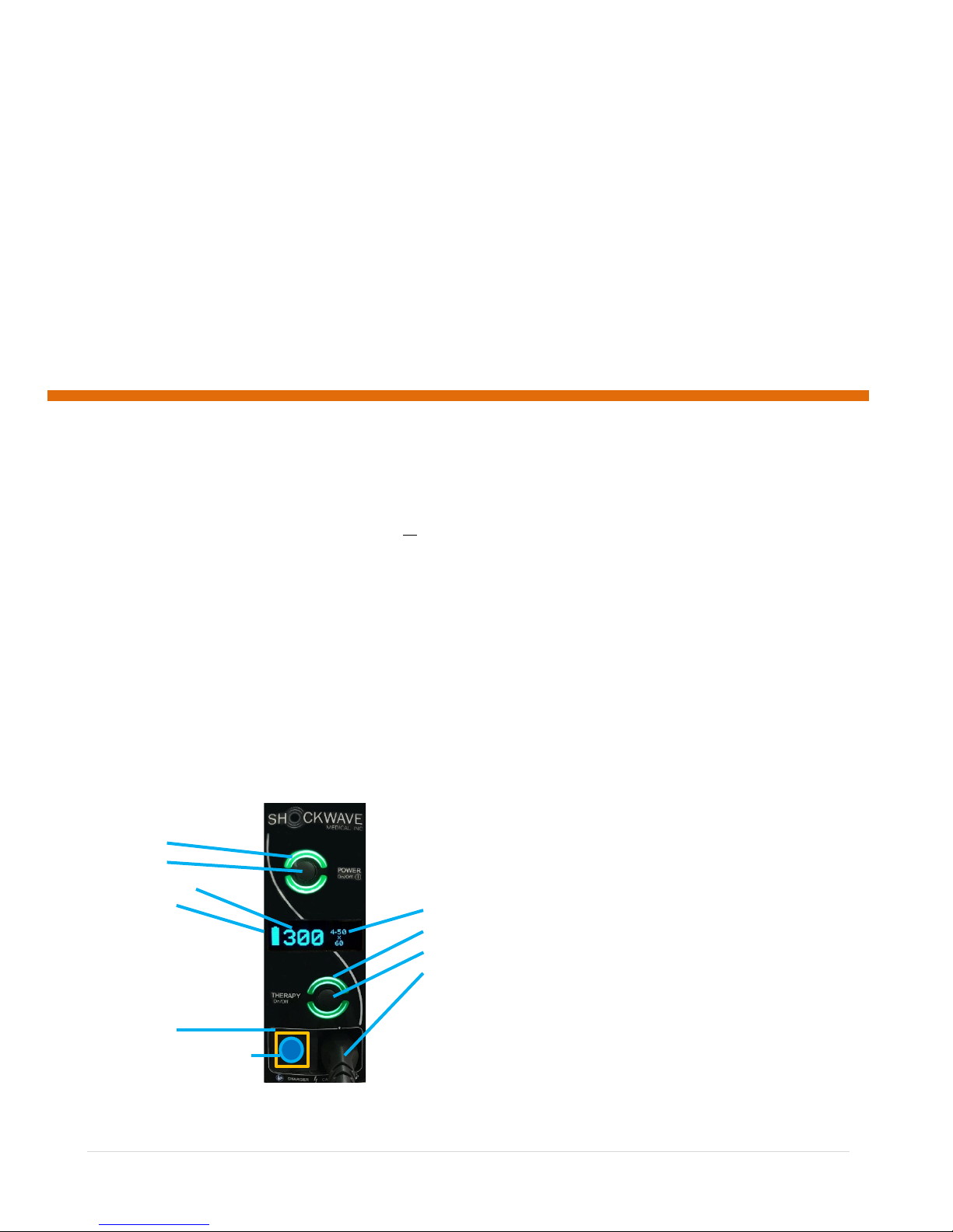
3.1 IVL Generator - Front View
LBL 61876 rev. E, March 2018 EN 3
Power On/Off
Remaining Pulse Count
Battery Capacity
Connector Door
Charger Connector (behind door)
Balloon Size
Therapy Status
Therapy On/Off
Therapy Connector
Page 4
3.2 Control and Indicator Functions
CONTROL
DESCRIPTION
MORE INFO
POWER ON/OFF
Turns IVL Generator on or off.
Refer to 3.1 IVL Generator Front View
THERAPY ON/OFF
Press to activate the IVL Generator.
IVL Connector Cable and a valid IVL Catheter must be
INDICATOR
DESCRIPTION
MORE INFO
POWER STATUS Indicator
On green when IVL Generator is on.
Refer to 3.1 IVL Generator Front View
On yellow when user action is required regarding the IVL Catheter (CATH).
See Section 4 step 6.
On red when internal diagnostics have detected a problem (SYS).
See Section 7.
BATTERY CAPACITY
Display/ Charging Status
Indicates bat tery charge remaining.
See Section 4 step 2.
BATTERY CHARGING
Lightning bolt symbol appears when the Charger Module is connected and is charging
Charge IVL Generator before use. See Sections 5.2 and 5.3.
BALLOON SIZE Display
IVL Catheter Balloon Diameter and Length
When IVL Connector Cable and valid IVL Catheter
connected.
PULSE COUNT Display
Number of Pulses available.
Counts down from available Pulse Count Per Catheter during
Catheter IFU for the Max Pulse Count.
THERAPY STATUS
Indicator
On green when the device is ready to deliver therapy. Flashes to indicate therapy is
in process. On yellow when therapy is paused or deactivated.
See Section 4, Steps 5 – 9.
FEATURE
DESCRIPTION
MORE INFO
CONNECTOR DOOR
Slide right to connect charger.
Slide left to connect IVL Connector Cable.
See Section 4,
Step 4.
CHARGER CONNECTOR
Used to connect to charger module.
See Section 5.3
THERAPY CONNECTOR
Used to connect to IVL Connector Cable (the Connector Cable connects the IVL
Generator to the IVL Catheter).
See Section 4
Step 4.
Catheter Connector
connected to activate.
Indicator
the battery from mains power.
treatment as each pulse is delivered. Refer to applicable IVL
3.3 Front Panel Connectors
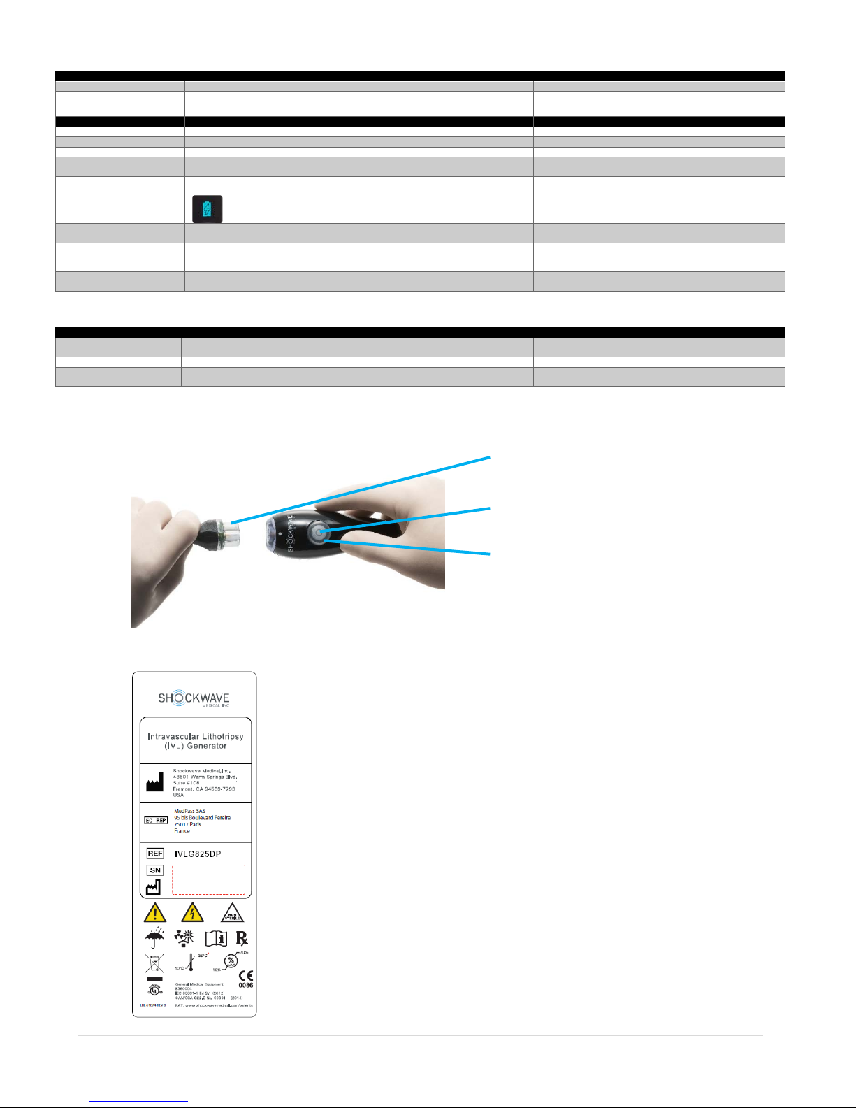
3.4 IVL Connector Cable
Pressing and holding the THERAPY CONTROL on the IVL Connector Cable initiates therapy delivery. The IVL Generator must first be activated (THERAPY STATUS indicators on
IVL Generator front panel and CATHETER CONNECTOR will be green). Refer to Section 4.0, Step 8 for more information.
Therapy Control
Therapy Status
3.5 IVL Generator – Rear View
There are no controls or indicators on the rear of the IVL Generator. Refer to Appendix B for more information regarding the symbols used.
LBL 61876 rev. E, March 2018 EN 4
Page 5
Step
Picture or additional info if app lic ab le
Slide CONNECTOR DOOR to left to reveal the
4. Product Use and Therapy Delivery
Before use read all sections of this operator’s manual and familiarize yourself with all controls, display s and connector features. Charge the IVL Generator before use (see
Sections 5.2, 5.3). Also refer to the IFU provided with the IVL Catheter for additional information before use. Not all clinical procedures will fol low the sequence below. The
following steps serve as a guide for use of the IVL Generator in clinical applications.
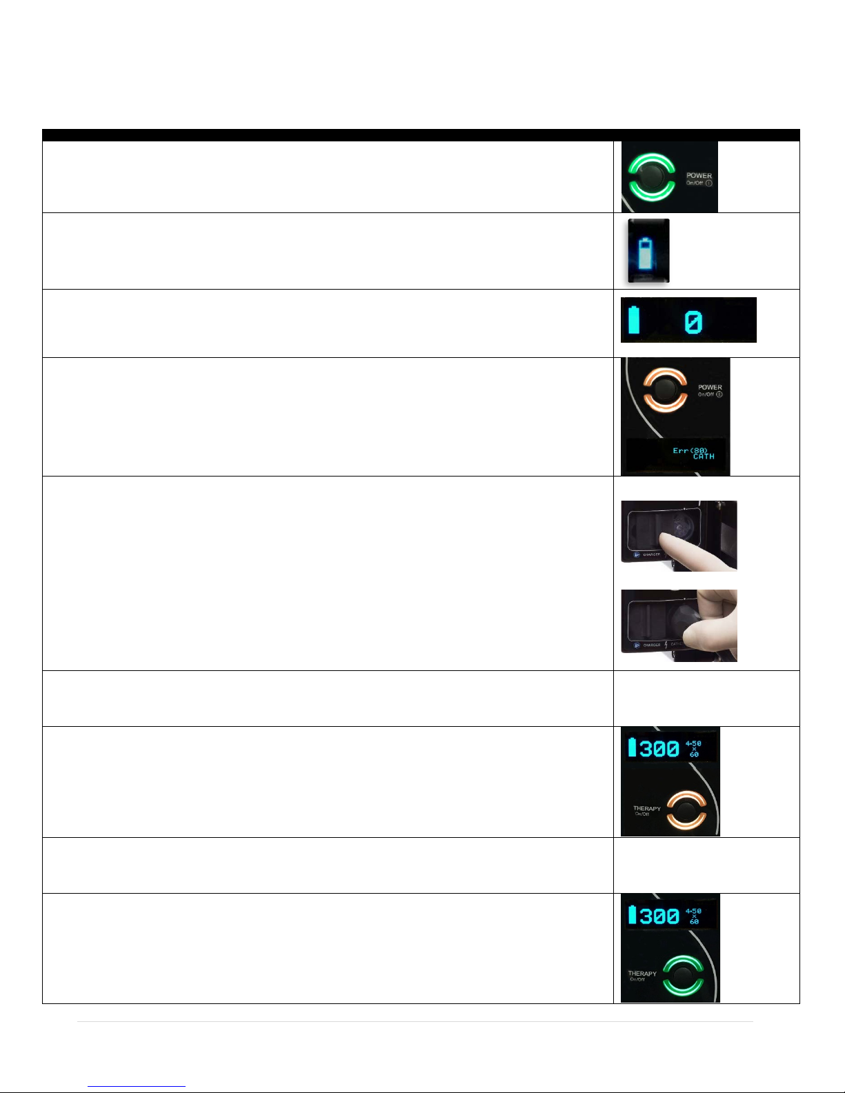
Step 1 – Turn the Generator On
Momentarily depress the POWER ON/OFF button. All indicators on the IVL Generator will come on briefly as a test. The THERAPY STATUS
indicator will come on yellow and green during this test. The POWER STATUS indictor will continue to be on green.
Step 2 – Confirm Battery Capacity
With the Generator powered on, the BATTERY CAPACITY will be shown in the right side of the display. The battery symbol should be at least
partially fi lled as shown.
If the battery symbol is empty, additional charging of the battery is recommended before use because there may not be an adequate charge to
complete a patient treatment.
Step 3 – Check Diagnostics
Confirm that the display is as pictu red with no error messages displayed. If an error message is displayed, refer to Troubleshooting, Section
7.0.
Normal display with no errors shown to the right.
If a yellow light is displayed, refer to Troubleshooting, Section 7.0.
If any error messages come on during use, refer to Troub l esho oting, Section 7.0.
Error Condition – Catheter error sh own to the right.
Step 4 – Connect IVL Connector Cable
Disconnect the Charger Module from the CHARGER CONNECTOR if it is connected.
Slide the CONNECTOR DOOR fully to the left, revealing the THERAPY CONNECTOR as shown.
Connect the GENERATOR CONNECTOR end of the Connector Cable to the THERAPY CONNECTOR. Orient the connector and gently push in.
The connector is magnetic and will engage as the magnet gets close. Push gently to confirm connector is fully engaged.
Step 5 – Prepare IVL Catheter for Use
Prepare the catheter for use following the instructions in the IVL Catheter IFU. Use a sterile sleeve to cover the distal end of the IVL Connector
Cable. Protect the connector from contamination by fluids.
THERAPY CONNECTOR
THERAPY CONNECTOR:
N/A
Step 6 – Connect IVL Catheter
Take care not to c o ntaminate eithe r c onnector end with fluids or other forei gn matter during this procedure prior to mating.
Connect the IVL Catheter to the CATHETER CONNECTOR end of the IVL Connector Cable using the same method outlined in step 4.
NOTE: Ensure that the sterile sleeve also covers the CATHETER CONNECTOR.
The THERAPY STATUS indicator on the IVL Generator front panel and the CATHETER CONNECTOR will be yellow, indicating that the IVL
Generator is ready to activate.
The IVL Catheter balloon dimensions will appear in the BALLOON SIZE display. The total number of available pulses for the selected IVL
catheter will appear in the PULSE COUNT field.
Step 7 – Position the IVL Catheter
Following conventional angioplasty catheter technique, introduce and position the IVL Catheter as desired. Use caution to prevent unintentional
movement of the IVL Connector Cable and IVL Catheter during treatment.
Step 8 – Activate the IVL Generator
Inflate the IVL Catheter and verify pressure per the instructions indicated in the IVL Catheter IFU. Press the THERAPY ON/OFF button once.
The THERAPY STATUS indicator on the IVL Generator front panel and on the CATHETER CONNECTOR will now be green, indicating that the IVL
Generator is now ready to deliver therapy. To deactivate the IVL Generator at any time, simply press the IVL Generator THERAPY ON/OFF
button again and verify that the THERAPY STATUS indicator light is yellow.
LBL 61876 rev. E, March 2018 EN 5
(Refer to the IVL Catheter IFU)
Page 6

Step
Picture or additional info if app lic ab le
Step 9 – Deliver Therapy
CAUTION
EQUIPMENT DAMAGE
TOPIC
ADDITIONAL INFORMATION
Tones
The IVL Generator is designed to supplement its visual indicators with tones. The IVL Generator will sound tones as follo ws:
Generator is deactivated and in the event built in diagnostics detect a malfun ct ion.
Use of
• Multiple IVL Catheters may be used and re-used during the treatment of a single patient. The IVL Generator is designed to track the useful remaining life of
patient injury.
Automatic
The IVL Generator is designed to turn itself off and conserve battery power after periods of inactivity as follows:
following steps outlined in Section 4.0.
Following
Follow these steps to prepare the IVL Generator for future use:
While observing balloon positioning and lesion characteristics under fluoroscopy, press and hold the THERAPY button on the IVL Connector
Cable. The IVL Generator will deliver lithotripsy pulses via the IVL Catheter balloon while the THERAPY button is depressed unless the IVL
Generator determines that therapy is to be interrupted. As each therapy pulse is delivered, the THERAPY STATUS indicator will blink once, the
PULSE COUNT display will decrement by one, and the Generator will sound one click. Confirm therapy delivery by continuously monitoring under
fluoroscopy (see IVL Catheter IFU for ad ditional informatio n). To stop therapy, simply release the THERAPY button.
NOTE: There is no need to make any adjustments for dosage levels or pulse rates. All such settings are pre-programmed for given catheter
types.
Step 10 – Pause Period / Resume Therapy
The IVL Generator is designed to force a brief pause in therapy at designated intervals. If the user attempts to deliver a quantity of pulses
without pausing, the IVL Generator will automatical ly interrupt therapy for a pause period. The THERAPY STATUS indicator will be yellow durin g
this period. To resume the rapy, wait for the T HERAPY STATUS indicator to become green again (two beeps will sound). Simply release and
press the THERAPY CONTROL again to resume therapy. Refer to the applicable IVL Catheter IFU for specifics on the maximum number of
continuous pulses allowed and the duration of the pre-programmed pause period. Care must be taken not to exceed the recommended
maximum number of pulses in the same treatment segment.
Step 11 – IVL Catheter End of Life
The IVL Generator is designed to sense the end of the useful life of the IVL Catheter. Should this occur the PULSE COUNT will indicate “0”
pulses remaining and the IVL Generator will interrupt therapy. The display will indicate a catheter error and a yellow light will appear around the
POWER ON/OFF button. Replacing the IVL Catheter with a new one is required before the IVL Generator may be used again. Refer to the
applicable IVL Catheter IFU for maximum pulse count per catheter (useful life ) specifications.
Step 12 – IVL Catheter Replace ment
Detach the IVL Catheter by first sliding the sterile sleeve out of the way moving it proximally along the IVL Connector Cable. Next, gently pull
the CATHETER CONNECTOR and IVL Connector Cable apart to separate the IVL Catheter from the IVL Connector Cable connector (see
illustration). Take care not to contaminate the connectors with fluids or other foreign matter during this procedure. Position IVL Connector
Cable to help ensure the connector remains free of contamination until the IVL Catheter can be replaced.
CAUTION: Discard the used IVL Catheter per standard hospital procedures. Used IVL Catheters cannot be re-sterilized and are designed f o r
single use only. Re-use of IVL Catheters can lead to patient injury. Connect a new IVL Catheter and resume patient treatm ent following the
steps outlined above, beginning at step #5. Refer to the IVL Catheter IFU for information about reco m mended balloon overlap to prevent
geographic miss. However, care must be taken not to exceed the recommended maximum number of pulses in the same treatment segment as
indicated in the IVL Catheter IFU.
The IVL Generator delivers low-energy, short-duration, high-voltage pulses to the IVL Catheter through the IVL Connector Cable. The system is designed not to deliver
pulses unless an IVL Catheter connector is mated with the IVL Connector Cable and IVL Generator. It is important not to allow the contacts or internal surfaces of
unmated connectors to be contaminated with fluids. Do not allow any connector to become contaminated by or immersed in fluids. Failure to observe these
precautions may damage the cables or catheters.
4.1 Additional Usage Information
The following topics and additional information may be useful in the use of the IVL Generator in treatment scenarios that may differ from the basic sequence of events defined
in Section 4.0 above.
• Click – Sounds once per therapy pulse to confirm therapy delivery in process.
• Two bee ps – Positive confirmation of a user action. Occurs when connecting a valid catheter or when arming or disarming the IVL Generator. Also occurs at
the end of the pre-programmed therapy pause period.
• Th ree beeps – Negative prompt. Occurs when attempting to activate the IVL Generator but when one or more conditions are preventing activation. Examples
include attempting to activate the IVL Generator without a valid IVL Catheter attached or while holding down the THERAPY button. Also occurs when the IVL
Multiple IVL
Catheters
Off Feature
Usage
NOTE: The battery is self-discharging and requires periodic recharges even during storage so that the battery will not discharge to an unacceptably low voltage level, which
could ultimately result in battery damage.
LBL 61876 rev. E, March 2018 EN 6
each IVL Catheter; however, no more than one of any given size IVL Catheter may be in use simultaneously.
• Connect and use IVL Catheters of varying size s by following steps 5 – 9 above.
• Discard used IVL Catheters after patient treatment. Used IVL Catheters cannot be re-sterilized and are for single use only. Re-use of IVL Catheters can lead to
• No IVL Catheter is connected – Will turn off after five hours.
• IVL Catheter connected – Will turn off after one hour.
• If the IVL Generator has turned itself off, simply press the POWER ON/OFF button to turn the IVL Generator back on. Patient treatment m ay resume by
• Press POWER ON/OFF button once to turn the IVL Generator off.
• Remove and discard the IVL Catheter and sterile sleeve.
• Coil and secure the IVL Connector Cable
• Slide the CONNECTOR DOOR to the right to protect the THERAPY CONNECTOR
• If the last case of the day has been completed, or if the BATTERY CHARGING symbol is indicating empty, then place the battery on charge. The Charger Module
must be connected to AC Mains and to the IVL Generator CHARGER CONNECTOR per Sections 5.2 - 5.3.
• Confirm the IVL Generator is charging; a lightning bolt symbol should appear inside the battery symbol.
Page 7

IV Pole Mounting Bracket – Side A
Clamp Screws
IV Pole Mounting Bracket Insert
IVL Generator
5. Installation
Important - Follow all steps in Sections 5.0 – 5.5 prior to use of this product.
The IVL Generator is shipped as an assembled product, ready to install on an IV pole as outlined in Section 1.1. It is designed to be mounted t o an IV pole prior to use.
Once mounted, it will appear as shown below.
IV Pole Mounting Bracket
Charger Module
IV Pole
Care should be taken in selecting a stable IV pole which should have a wide base and locking-style casters. An IV pole with five casters, located i n a circular pattern with a
diameter of at least 23 inches (58 cm), such as the I.V. League Ventilator Stat-Stand™ model 1059 (or equivalent) is recommended.
The IVL Generator should be mounted such that its top surface is no more than 50 inches (127 cm) from the floor. Consult your biomedical department in the event there are
any questions regarding the stability of the intended IV pole and mounting location. Mounting the IVL Generator to an unstable IV pole could present a tip over hazard to staff
or patients.
5.1 IV Pole Mounting
STEP 1 – Locate and identify mounting hardware (see image below).
Two identical sets of IV pole mounting hardware are provided. One set is used to mount the IVL Generator and one set is used to mount the battery Charger Module.
IV Pole Mounting Hardwar e
STEP 2 –Determine the IV pole diameter at the desired mounting location.
The mounting brac ket will accommodate IV pole diameters from 3/4 to 1 inch (19 mm to 25 mm).
NOTE: If the pole diameter 1 inch (25 mm) proceed to step 3.
If the IV pole is 3/4 inch (19 mm) in diameter, attach the IV Pole Mounting Bracket Insert to the side B mounting bracket as shown below and proceed to step 3.
IV Pole Mounting Bracket Spring
IV Pole Mounting Bracket - Side B
IV Pole Mounting Bracket Mounting Screws
IV Pole Mounting Bracket Insert
IV Pole Mounting Bracket
Side B
IV Mounting Bracket Insert Screws
LBL 61876 rev. E, March 2018 EN 7
Page 8

STEP 3 – Mount the brackets to the IV Pole as follows:
IV Pole Mounting Bracket
IV Pole Mounting
Mounting
Allen Key
Clamp Screw
Tighten with Allen Key
Slide the bracket to the desired position on the pole for the battery charger. Install and tighten the clamp screw.
Bracket
Side A
Side B
Screw
(5/32”)
Install and tighten the remaining mounting (2ea) and clamp screws (1ea).
Install the second mounting bracket in the same fashion. Position the second bracket so that it rests on top of the first bracket. Orient the brackets so that they are facing
opposite directions.
STEP 4 – Mount the IVL Generator to the top bracket:
Align the holes in the mounting plate on the right side of the IVL Generator with the bracket mounting studs. Push the IVL Generator towards the bracket to engage the
mounting studs then push the IVL Generator down to lock in pl ac e.
(5/32")
LBL 61876 rev. E, March 2018 EN 8
Page 9

CAUTION – IV POLE TIP HAZARD
Observe the recommendations noted herein for mounting the IVL Generator to an IV pole. Failure to comply with recommendations could result in an injury to the user or
patient.
WARNING – SHOCK HAZARD
To avoid the risk of electrical shock, this equipment must only be connected to a grounded electrical outlet (electrical supply mains wit h protective earth.) U s e with a
Charger Module provided wi t h the IVL Generator to avoid shock.
WARNING – USE ENVIRONMENT
Allow the IVL Generator and its accessories (including IVL Catheters and IVL Connector Cables) to adjust to room temperature and humidity conditions for at least twenty
malfunction or damage.
Step
Picture or additional info if
applicable
Step 1 – Physical Condition Inspection
Step 2 – Confirm Battery Charging
Step 3 – Turn the IVL Generator On
IVL Generator
STEP 5 – Mount the battery Charger Module in the same fashion as the IVL Generator.
IV Pole Mounting Bracket
Charger Module
IV Pole
5.2 Connecting to Line Power
The IVL Generator normally operate s from an internal, rechargeable battery system. However, in order to charge the battery system, the Charger Module must first be
connected to line power. Locate the AC Mains Cable shipped with the IVL Generator and connect it to the AC Mains input as indicated in the figure on the next page. Choose
a safe location where connection of this power cable to AC Mains will not c reate a trip hazard and c o nnect it to the AC Mains outlet.
The Charger Module is designed to operate from power supplies world-wide. See Appendix C for more information.
hospital grade receptacle. Grounding reliability can only be achieve d when connected to an equivalent receptacle marked “hospital use” or “hospital grade”. Only use the
5.3 Charging the Internal Battery
Charging the battery requires the Charger Module be connected to AC Mains, and the Charger Module must also be connected to the CHARGER CONNECTOR located on the
front panel of the IVL Generator (see Section 3.1).
It will be necessary to disconnect the IVL Connector Cable from IVL Generator, if one is attached. To do so, gently pull the IVL Connector Cable connector straight from the
IVL Generator. Move the CONNECTOR DOOR fully to the right to cover the THERAPY CONNECTOR and expose the CHARGER CONNECTOR.
Connect the cable coming from the front of the Charger Module to the CHARGER CONNECTOR on the front of the IVL Generator (see Section 3.1). Ensure that the CHARGER
MODULE cable is fully seated into the CHARGER CONNECTOR. The BATTERY CHARGING indicator will be displayed with a lightning bolt inside the battery symbol to indicate
the battery is now charging (see Step 2 of Section 5.5 for illustration).
Charge the battery for at least twelve hours prior to use. After twelve hours, BATTERY CAPACITY should show a completely filled in battery symbol (see Step 4 of Section 5.5
for illustration).
NOTE: The battery is self-discharging and requires periodic recharges ev en during storage so that the battery will not discharge to an unacceptably low voltage level,
The IVL Generator is designed to be used indoors in a controlled environment. Refer to Appendix C for specified operating conditions.
Allow the IVL Generator to be stored in the ambient conditions of the usage environment for at least 24 hours before turning it on. This must be done with the IVL Generator
unpacked and removed from its shipment materials. This is important because shipping, storage and use environments may vary widely and could cause condensation within
the IVL Generator or its accessories. Such condensation could result in a possible malfunction or equipment damage if operated.
Inspection and test of the IVL Generator following installation per the steps below is recommended prior to placing the IVL Generator into clinical service. Also confirm that
the inspection and test requirements of your Biomedical Department have been satisfied prior to placing this equipment into clinical service.
Inspect all surfaces of the IVL Generator exterior including the Charger Module. Confirm there is no visible damage such as cracks or
chips in any component.
Disconnect the Charger Module from the IVL Generator and slide the CONNECTOR DOOR left and right. Verify it is not damaged, also
verify it is retained in its track and it slides easily left to right. Reconnect the Charger Module to the IVL Generator.
Inspect the IVL Connector Cable and AC Main s Cable. Confirm the re are not any damaged, split or cracked mat erials and electrical
contacts are free of extraneous matt er.
which could ultimately result in battery damage.
5.4 Environment Conditioning
four hours before use. See Appendix C for specified operating conditions. Operating the equipment outside of these environmental conditions may cause equipment
5.5 Generator Inspection and Test
The Charger Module must be connected to AC Mains and to the IVL Generator CHARGER CONNECTOR per Sections 5.2 - 5.3.
Confirm the BATTERY CHARGING indicator is displayed.
Momentarily depress the POWER ON/OFF button. The POWER STATUS and THERAPY STATUS indicators will turn on briefly as a test. The
indicators will come on green and then yellow during this test. The POWER STATUS indicator will remain green if no internal fault is
detected. The THERAPY STATUS indicator will turn off.
LBL 61876 rev. E, March 2018 EN 9
Page 10

Step
Picture or additional info if
applicable
Step 4 – Confirm Battery Capacity
Step 5 – Check Diagnostics
Error Conditio n
Step 6 – Initiate the Output Test
Step 7 – Confirm Output Test Result
WARNING – SHOCK HAZARD
Do not immerse IVL Connector Cables in water or other fluids. Avoid spilling any fluids on the IVL Generator. Spilled liquids may cause the IVL Generator to perform
Confirm Battery Charging
Confirm Battery Capacity
BATTERY SYMBOL
CAPACITY
Completely Filled
Fully charged
½ Full
Four or more treatment cases
¼ Full
Two or more treatment cases
Empty
Less than two treatment cases; rech arge as soon as practical
If the battery has been charging for at least twelve hou rs, as indicated in Se ction 5.3, the battery capacity shown in the BATTERY CAPACITY
display should be full as shown.
When powered on, the IVL Generator will perform an array of built in tests designed to detect certain malfunctions. If an error is detected, an
error message will be displayed. If there are no error messages, these t ests passed successfully.
If an error message is dis played, refer to Troubleshooting, Section 7.0.
This test is initiated manually by depressing and holding the THERAPY ON/OFF button and releasing this button when the THERAPY STATUS
indicator comes on green. Pressing this button for three seconds is required.
The output test requires approximately 15 seconds to complete. During this time the THERAPY STATUS indicator will remain on green. Upon
successful completion of this test, the IVL Generator will sound four beeps. If an error is detected, an error message will be displayed. If the
display remains blank with only the battery symbol, this test h as passed successfully.
This is the final step of the recommended inspection and test procedure.
Normal
inaccurately or malfunction.
6. Maintenance
This section describes the maintenance that cl inical and / or biomedical staff should be familiar with performing on a regular basis. Recommendations for regular maintenance
and maintenance intervals are noted below.
NOTE: The battery is self-discharging and requires periodic recharges even during storage so that the battery will not discharge to an unacceptably low voltage level,
6.1.1 Charging and Testing the Internal Battery
The Charger Module must be connected to AC Mains and to the Generator CHARGER CONNECTOR per Sections
5.2 - 5.3.
Confirm the BATTERY CHARGING indicator is displayed.
If the battery has been charging for at least twelve hou rs the battery capacity shown in the BATTERY CAPACITY
display should indicate full as shown.
See the table on the next page for battery capacity information.
which could ultimately result in battery damage. There are no user serviceable parts within the IVL Generator. Do not open the IVL Generator enclosure. Refer all
such servicing needs to your Shockwave Medical representative.
6.1 Daily Maintenance
The IVL Generator operates from an internal battery. Charging the IVL Generator at the end of each day is recommended so that the battery will be fully charged
for cases occurring the followin g day. Twelve (12) hours of charge time will restore the battery to full charge.
LBL 61876 rev. E, March 2018 EN 10
Page 11

A treatment case, for the purposes of interpreting the BATTERY CAPACITY display, is conservatively defined as 900 therapy pulses delivered over one hour. Actual battery
WARNING – POSSIBLE DEVICE SHUTDOWN
This device operates only from an in ternal battery source. Charge the IVL Generator battery when not in use. Always operate the IVL Generator when the battery
Shockwave Medical representative in the event the battery symbol frequently appears Empty or if the battery symbol does not appear full after twelve hours of chargin g .
Step
Picture or additional info if applicable
Step 1 – Turn the IVL Generator On
Step 2 – Check Diagnostics
Step 3 – Initiate the Output Test
Step 4 – Confirm Output Test Result
Physical Condition Inspection
WARNING – SHOCK OR FIRE HAZARD
Do not immerse any portion of the IVL Generator in water or other fluids. Do not immerse IVL Connector Cables in water or other fluids. Avoid spilling any fluids on the
Do not autoclave or sterilize the IVL Generator or IVL Connector Cables as this may cause the IVL Generator to malfunction.
performance will vary based on actual therapy delivered.
If the battery does not indicate full charge following twelve (12) hours of charging, remove the IVL Generator from service and cont act your Shockwave Medical
representative.
NOTE: The battery is self-discharging and requires periodic recharge s even during storage so that the battery wi ll not discharge to an unacceptably low voltage level,
which could ultimately result in battery damage.
symbol is at least ¼ Full. IVL Generator may shut down without warning when the battery symbol is Empty. Remove the IVL Generator from u se and contact your
6.1.2 Testing the IVL Generator
The IVL Generator will automatically perform an array of built in tests de s igned to detect certain malfunctions eac h time it is turned on. In addition, the IVL
Generator features an automated test of the lithotripsy output system which may be initiated by the user. Confirmation of satisfactory test results is
recommended daily, before cases are initiated, or as directed by your Biomedical Department. These tests may be done as follows:
Momentarily depress the POWER ON/OFF button. All indicators on the IVL Generator will come on briefly as a test. The THERAPY STATUS
indicator will come on green and yellow during this test. The POWER STATUS indictor will continue to be on green.
When powered on, the IVL Generator will perform an array of built in tests designed to detect certain malf unctions. If an error is detected,
an error message will be displayed. If no error is displayed, these tests passed successfully.
If an error message is dis played, refer to Troubleshooting, Section 7.0.
The Charger Module must be connected to AC Mains and to the IVL Generator CHARGER CONNECTOR to run this test.
This test is initiated manually by depressing and holding the THERAPY ON/OFF button and releasing this button when the THERAPY STATUS
indicator comes on green. Pressing this button for three seconds is required.
The output test requires approximately 15 seconds to complete. During this time the THERAPY STATUS indicator will remain on green.
Upon successful completion of this test, the IVL Generator will sound four beeps. If no error message appears on the display then this test
has passed successfully.
6.1.3 Inspecting the IVL Generator
Physical inspection of the IVL Generator on a daily basis is also recommended to help ensure th at all components required for reliable operation are in goo d condition.
Inspect all surfaces of the IVL Generator exterior including the Charger Module. Confirm there is no visible damage such as cracks or chips
in any component.
Disconnect the Charger Module from the IVL Generator and slide the CONNECTOR DOOR left and right. Verify it is not damaged, also
verify it is retained in its track and it slides easily left to right. Reconnect the Charger Module to the Generator.
Inspect the IVL Connector Cable and AC Mains Cable. Confirm there are not any damaged, s plit or cracked materials and electric al
contacts are free of extraneous matt er.
6.1.4 Cleaning the IVL Generator
Dirt and extraneous matter may be removed from the IVL Generator and IVL Connector Cable using a soft cotton cloth or a lint free wipe. If needed, use only isopropyl
alcohol sparingly as a cleaning agent .
Do not allow any fluids to penetrate the exterior surfaces o f the device. Allow equipment to dry thoroughly before testing or use.
Clean connector areas carefully . Do not attempt to clean interior surfaces of connectors or con nector contacts. In the event that an IVL Connector Cable has become
contaminated or malfunctions, remove this cable from use and contact your Shockwave Medic al representative.
IVL Generator. Spill ed liquids may cause the IVL Generator to perform inaccurately or malfunction.
Do not clean with solvents or flammable agents as this may cause damage to the IVL Generator and possibly cause harm to the user
6.2 Monthly Maintenance
There is no specific test or inspection which is recommended to be conducted on a monthly basis in addition to the tests and inspections included in Section 6.1. However, it
is recommended that the shift supervisor or Biomedical Department review staff practices on a monthly basis to help ensure this recommended maintenance is being
completed on a daily basis or as directed by the Biomedical Department .
LBL 61876 rev. E, March 2018 EN 11
Page 12

6.3 Other Maintenance
WARNING – SHOCK HAZARD
Do not attempt to service the system. It contains no operator serviceable co m po nents and dangerous high voltages may be present. No use r m o dification or servicing of this
equipment is allowed. If any part of this product appears damaged, remove from use and contact your Shockwave Medical representative for repair or replacement.
Observation
Possible Cause
Corrective Action
Connect Charger Module to the IVL Generator and to AC
prior to use
Turn IVL Generator off, wai t one second and turn the IVL
representative.
Make sure IVL Connector Cable is connected to IVL
Cable
Make sure IVL Connector Cable is connected to IVL
Replace IVL Catheter
Shockwave Medical recommends that you contact your Shockwave Medical representative if you have any questions or concerns about maintenance.
Shockwave Medical recommends replacement of IVL Connector Cables every three years to reduce the possibility of failure during patient use. In the event IVL Connector
Cable connectors have become contaminated or the IVL Connector Cable malfunctions, remove this cable from use and contact your Shockwave Medical representative for a
replacement. Additional IVL Connector Cables can be ordered separately.
NOTE: The IVL Connector Cable should not be disposed of in the n ormal waste stream; it should be sent to a s eparate collection facility for recovery and recycling.
6.4 Product Useful Life
The IVL Generator has been designed to provide a useful life of three years or more. Life expectancy is based on actual usage. Periodic inspection per the maintenance
schedule above is recommended by Shockwave Medical t o assess con t inued use.
7. Troubleshooting
If a problem is detected with the IVL System during use or testing, refer to the troubleshooting tips below. If the problem cannot be corrected, remove the equipment from
service and contact your Shockwave Medical representative and or email complaints@shockwavemedical.com.
Technical Support: For Shockwave Medical Technical Support, contact your local Shockwave Medical representative or www.shockwavemedical.com.
Connect Charger Module to the IVL Generator and to AC
Unit will not turn on Battery requires charge
Battery will not charge
(BATTERY CHARGING indicator is off)
Low BATTERY CAPACITY indicated when the
battery symbol is Empty
Disconnected cable
Battery requires charge
Mains.
Allow the IVL Generator to charge at least twelve (12) hours
prior to use
Connect Charger Module to the IVL Generator and also to
AC Mains.
NOTE: two cable connections are required.
Mains.
Allow the IVL Generator to charge at least twelve hours
System Error displayed and red light around
POWER ON/OFF button.
Catheter Error Displayed
THERAPY STATUS indicator on IVL Generator front
panel or on the IVL Connector Cable does not turn
on
IVL Generator will not activate
(THERAPY STATUS is off)
IVL Generator will not activate
(THERAPY STATUS is yellow)
THERAPY STATUS changed fro m green to yellow
THERAPY ON/OFF button on the IVL Connector
Cable is pressed, but IVL Generator does not
deliver pulses
Built in tests have detected a malfunction within the IVL
Generator
Catheter connection has not been made properly or has
become disconnected.
IVL Catheter has reached its useful life or is defective Replace IVL Catheter
IVL Connector Cable has reached its useful life Replace Connector Cable
Valid IVL Catheter is not connected
Valid IVL Catheter is not connected See THERAPY S TATUS indicator troubleshooting step above
THERAPY ON/OFF button is pressed Release THERAPY ON/OFF button, try again
IVL System has automatically paused therapy (see Section
4.0 Step 10
IVL Generator cannot be activated
(THERAPY STATUS indicator is off)
IVL Generator has not yet been activated (THERAPY STATUS
indicator is yellow)
IVL System has automatically paused therapy (THERAPY
STATUS indicator is yellow, see Section 4.0 Step 9)
IVL Catheter or IVL Connector Cable is faulty
(THERAPY STATUS indicator is green)
Generator on again.
NOTE: If SYS fault cannot be resolved, remove IVL
Generator from service and contact your Shockwave Medical
Generator
Make sure vali d IVL Catheter is connected to IVL Connector
Generator
Make sure IVL Catheter is connected to IVL Connector Cable
THERAPY STATUS should indicate green again, within the
pause period specified in the IVL Catheter IFU
If error message(s) appear, see troubleshooting guide
above
Press THERAPY ON/OFF button once (THERAPY STATUS
should turn green)
THERAPY STATUS should indicate green again, within the
pause period specified in the IVL Catheter IFU
Replace IVL Catheter
Replace IVL Connector Cable
LBL 61876 rev. E, March 2018 EN 12
Page 13

8. Appendix A: Electromagnetic Compatibility Guidance
Guidance and manufacturer’s declaration – electromagnetic emissions
The Generator Model 825DP is intended for use in the electromagnetic environment specified below.
Emissions test
Compliance
Electromagnetic enviro nm ent – guidance
RF emissions CISPR 11
Group 1
The Generator Model 825DP uses RF energy only for its internal function. Therefore, its RF emissions
RF emissions CISPR 11
Class A
The Generator Model 825DP is suitable for use in all establishments other than domestic and those
Harmonic emissions IEC 61000-3-2
Class A
Voltage fluctuations/flicker emissions IEC 61000-3-3
Complies
Guidance and manufacturer’s declaration – electromagnetic immunity
The Generator Model 825DP is intended for use in the electromagnetic environment specified below. The
customer or the user of the Generator, Model 825DP should assure that it is used in such an environment.
Immunity test
IEC 60601 test level
Compliance level
Electromagnetic environment –guidance
Electrostatic discharge (ESD)
± 6 kV contact
± 6 kV contact
Floors should be wood, concrete or ceramic tile. If flo o rs are
be at least 30 %.
Electrical fast transient/burst
± 2 kV for power supply lines
± 2 kV for power supply lines
Mains power quality should be that of a typical commercial or
Surge
IEC 61000-4-5
± 1 kV line(s) to line(s)
± 2 kV line(s) t o earth
± 1 kV line(s) to line(s)
± 2 kV line(s) t o earth
Mains power quality should be that of a typical commercial or
hospital environment.
Voltage dips, short
<5 % UT (>95 % dip in UT) for 0,5 cycle
<5 % UT (>95 % dip in UT) for 0,5 cycle
Mains power quality should be that of a typical commercial or
Power frequenc y (50/60 Hz)
IEC 61000-4-8
3 A/m
3 A/m
Power frequency magnetic fields should be at levels
hospital environment.
NOTE: UT is the A.C. mains voltage prior to application of the test level.
Guidance and manufacturer’s declaration – electromagnetic immunity
The Generator, Model 825DP is intended for use in the electromagnetic environment specified below. The customer or the user of the Generator, Model 825DP should assure that it is used in
such an environment.
Immunity test
IEC 60601 test level
Compliance level
Electromagnetic enviro nm ent – guidance
Conducted RF
3 Vrms 150 kHz to 80 MHz
[V1=3] V
Portable and mobile RF communications equipment should be used no closer
NOTE 1 At 80 MHz and 800 MHz, the higher frequency range applies.
a) Field strengths from fixed transmitters, such as base stations for radio (cellular/cordless) telephones and land mobile radios, amateur radio, AM and FM radio broadcast and TV broadcast
b) Over the frequency range 150 kHz to 80 MHz, field strengths should be less than [V1] V/m.
Electromagnetic Compatibility Guidance - Emissions
The customer or the user of the Generator Model 825DP should assure that it is used in such an environment.
are very low and a re not likely to cau se any interference in nearby electronic equipment.
directly connected to the public low-voltage power supply network that supplies buildings used for
domestic purposes.
Electromagnetic Compatibility Guidance – Power Supp ly Immunity
IEC 61000-4-2
IEC 61000-4-4
interruptions and voltage
variations on power supply
input lines
IEC 61000-4-11
magnetic field
Electromagnetic Compatibility Guidance – RF Immunity
IEC 61000-4-6
Radiated RF
IEC 61000-4-3
± 8 kV air
± 1 kV for input/output lines
40 % UT (60 % dip in UT) for 5 cycles
70 % UT (30 % dip in UT) for 25 cycles
<5 % UT (>95 % dip in UT) for 5 s
3 V/m 80 MHz to 2,5 GHz
± 8 kV air
± 1 kV for input/output lines
40 % UT (60 % dip in UT) for 5 cycles
70 % UT (30 % dip in UT) for 25 cycles
<5 % UT (>95 % dip in UT) for 5 s
[E1=3] V/m
to any part of the Generator Model 825DP, including cables, than the
recommended separation distance calculated from the equation applicable to
the frequency of the transmitter.
Recommended separation distance
covered with synthetic material, the relative humidity should
hospital environment.
hospital environment. If the user of the Generator Model
825DP requires continued operation during power mains
interruptions, it is recommended that the Generator Model
825DP be powered from an uninterruptible power supply or a
battery.
characteristic of a typical location in a typical commercial or
where P is the maximum output power rating of the transmitter in watts (W)
according to the transmitter manufacturer and d is the recommended
separation distance in meters (m). Field strengths from fixed RF transmitters,
as determined by an electromagnetic site survey
compliance level in each frequency range
vicinity of equipment marked with the following symbol:
NOTE 2 These guideline s may not apply in all situations. Electromagneti c propagation is affec ted by absorption and reflection from structures, objects and people.
cannot be predicted theoretically with accuracy. To assess the electromagnetic environment due to fixed RF transmitters, an electromagnetic site survey should be considered. If the
measured field strength in the location in which the Model 825DP is used exceeds the applicable RF compliance level above, the Model 825DP should be observed to verify normal operation.
If abnormal perf o rmance is observed, additional measures may be necessary, such as re-orienting or relocating the Model 825DP.
LBL 61876 rev. E, March 2018 EN 13
a
, should be less than the
b
Interference may occur in the
Page 14

Electromagnetic Compatibility Guidance – Separation Distances
Recommended separation distances between portable and mobile RF communications equipment and the Model 825DP
The Generator Model 825DP is intended for use in an electromagnetic environment in which radiated RF disturbances are controlled. The customer or the user of the Generator Model 825DP can
Rated maximum output power
Separation distance according to frequency of transmitter (m)
150 kHz to 80 MHz
80 MHz to 800 MHz
800 MHz to 2,5 GHz
0.01
0.12
0.12
0.23
0.1
0.37
0.37
0.74 1 1.17
1.17
2.33
10
3.69
3.69
7.38
100
11.67
11.67
23.33
For transmitters rated at a maximum output power not listed above, the recommended separation distance d in metres (m) can be estimated using the equation applicable to the frequency of
NOTE 2 These guidelines may not apply in all s ituations. Electromagnetic propagation is affected by absorption and reflection from structures, objects and people.
Symbol
Description
Symbol
Description
10%
70%
help prevent electromagnetic interference by maintaining a minimum distance between portable and mobile RF communications equipment (transmitters) and the Generator Model 825DP as
recommended below, according to the maximu m output power of the communications equipment.
of transmitter
(W)
the transmitter, where P is the maximum output power rating of the transmitter in watts (W) according to the transm itter manufacturer.
NOTE 1 At 80 MHz and 800 MHz, the separation distance for the higher frequency range applies.
Essential Performance
Generator Model 825DP maintains safe and effective performance in the delivery of IVL therapy when operated in the electromagnetic environment specified in the table
above.
9. Appendix B: Symbols
The IVL Generator bears the following s ymbols:
Refer to instruction manual
Read and understand the Operator’s M anual before use.
10° C
35°C
Temperature limit
Consult instructions for use
Caution
Non-sterile
Type CF
The IVL Generator is classified fo r use without equipment damage in the
presence of car d iac defibrillators. The applied part meets electrical
safety requirements for cardiac use.
Catalogue number
Serial number
Protect from heat and radioactive sources
Warning dangerous voltage
Caution: Federal (USA) Law restric ts this device to s ale by or on the
order of a physic ian.
Humidity limitation
Date of manufacture
Manufacturer
Keep dry
Do not use if package is damaged
Authorized Representative in the European Community
Do not stack
Waste from Electrical and Electronic Equipment Directive
The Generator and Connector Cable should not be disposed of in
the normal waste s tream and should be s ent to separate collection
facilities for recovery and recycling.
Conformité Européenne
PAT
IVL
Generator
Patents. Refer to www.shockwavemedical.com/
Intravascular Lithotripsy (IV L) Generator
LBL 61876 rev. E, March 2018 EN 14
patents Refurbished
The process or combination of processes applied during the
expected service life to restore used equipment to a condition of
safety and performance comparable to when new.
Page 15

10. Appendix C: Specifications
Specifications
Performance Characteristics
Alarms
Built in tests and monitors are designed to detect and annunciate designated malfunctions of subsystems within the Generator. The Generator is
beeps will sound. See Sections 4 .1 (Tones), 7.0 (Troubleshooting)
Classification, Product
Class II Medical Electrical (ME) Equipment
Classification, Applied Parts
Type CF
Connectors (Connector
Cable)
OnAnOn 150PT series with proprietary keyway
Data Log
No data associated with patient cases is logged
Enclosure
Non-ventilated, polymeric enclosure, molded from flame re tardant UL 94V-0 rated material
Environmental
Altitude: 0 - 2000 meters
Temperature, storage / shipping: -20° to 65°C
Electrical Safety
ISO 60601-1 (2012) edition 3.1 standards
EMC Compatibility
See Appendix A
Mobility
Product is desi gned to be mounted to a stable mobile or statio nary IV pole. An IV pole with five casters located in a circular pattern with a diameter of
at least 23 inches (58 cm), such as the I.V. League Ventilator Stat-Stand™ model 1059 (or equivalent) is recommended.
Power
110 – 240 VAC; 50-60Hz; Single Phase, 15A service
Protectively earthed
Size
11” (28.0 cm) high x 6” (15.2 cm) wide x 11.5” (29.2 cm)deep
Shock
Shipping Shock per EXD-007C ASTM D 4169-09
Splash Resistance
10 mL saline from above (Generator)
100 mL saline from any angle (Connector Cable distal end)
Weight
15 pounds (6.8 kg)
Specifications
Performance Characteristics
Battery
Rechargeable Smart Lithium Ion Battery Pack (14.4V, 6.6Ah)
(UN Manual of T ests and Criteria part I II subsection 38.3)
Diagnostics
Built in tests and monitors are designed to detect and annunciate designated malfunctions of subsystems within the IVL Generator. The IVL Generator
is designed to interrupt therapy delivery in the event a malfunction is detected.
Emitter Drive Channels
Four channels, one to four channels may be used depending on catheter model connected.
Output
Proprietary pulse delivery system. Output voltage 1000 – 3000 volts peak to peak, pulse duration ~ 1μS, pulse frequency 1, 2 or 4 Hz depending on
Output Voltage Accuracy
The open circuit voltage at the IVL Generator THERAPY CONNECTOR: 5% of pre-programmed set point.
Output Limits
IVL System is designed to override user input and limit the number of continuous pulses delivered based on the IVL Catheter model connected. Refer to
IVL Catheter IFU.
Therapy Settings
Proprietary pulse delivery system. No user adjustable settings. Pulse delivery settings are pre-programmed, based on IVL Catheter model connected.
Settings and IVL Catheter model detection employ redundant features.
This appendix contains the specifications and performance characteristics for the Shockwave Medical IVL Generator Model 825DP. All specifications are typical at 20°C unless
otherwise stated.
10.1 Appendix C1: General Specifications
designed to interrupt therapy delivery in the event a malfunction is detected. In addition, visual annunciators (CATH or SYS) will activate and three
Humidity, operating: 10 – 70% non-condensing
Temperature, o perating: 10° to 35°C
10.2 Appendix C2: Performance Specifications
This appendix contains the specifications and performance characteristics for the Shockwave Medical IVL Generator Model 825DP.
Charge time less than twelve hou rs to full charge
Fully charged battery capacity 12 patient cases
(patient case: 900 therapy pulses delivered over one hour)
80% capacity after 300 full charge/discharge cycles
Meets require ments for transport via commercial aircraft
catheter model connected.
Shockwave Medical, Inc .
48501 Warm Springs Blvd., Suite 108
Fremont, CA 94539, USA
www.shockwavemedical.com
MedPass SAS
95 bis Boulev ard P ereire
75017 Paris
France
LBL 61876 rev. E, March 2018 EN 15
Page 16

Manufactured by Shockwave Medical, Inc.
MedPass SAS
France
PN 62393 Rev A
48501 Warm Springs Blvd., Suite 108
Fremont, CA 94539, USA
www.shockwavemedical.com/patents
95 bis Boulevard Pereire
75017 Paris
 Loading...