


Circularly Polarized FM
Broadcast Antenna
Versa2une (SLV)
1 to 4-bay, full-wave-spaced
Instruction Manual
Installation, Operation, &
Maintenance

Congratulations!
Thank you for purchasing one of the finest FM broadcast antennas on the
market today. The Shively Labs Versa2une is the top-of-the-line in its class for
its simplicity, superior performance and durability.
Your purchase is backed by the best technical support in the industry. Shively
is a leading manufacturer in the broadcast industry, providing an extensive
range of antennas, transmission line and components. Our technical staff has
a wealth of experience in the broadcast industry and is standing by to serve
you in any way.
This manual is intended to give you a good basic understanding of your
antenna: its proper and safe installation, startup, and operation, and trouble
shooting and maintenance information to keep it working satisfactorily for
years to come.
Please have everyone involved with the antenna read this
manual carefully, and keep it handy for future reference.
Meanwhile, please feel free to contact your sales representative at Shively
Labs at any time if you need information or help. Call or write:
-
Publication No. im-SLV_1-4_fw (150915)

IMPORTANT
Please read this manual in its entirety before beginning
installation of your antenna!
Failure to follow the installation and operation
instructions in this manual could lead to failure of your
equipment and might even void your warranty!
This manual applies only to one- to four-bay SLV antennas
(SLV-1 to SLV-4) with full-wave bay spacing. For six- to
twelve-bay antennas (SLV-6 to SLV-12) or any size half-wave-
spaced versions, refer to the appropriate manual on our
Web site.


Table of Contents
Chapter 1 Preparation........................................................................1
Check the shipment...............................................................................1
Torque specifications................................... ..........................................1
Table 1 Torque specifications .......................................................... 1
Check the parts.....................................................................................1
Prepare the mounting location. ..............................................................2
Figure 1 Tower layout, single-bay antenna....................................... 2
Figure 2 Tower layout, two-bay antenna.......................................... 3
Figure 3 Tower layout, four-bay antenna..........................................4
High-band or low-band? ....... .................................................................5
Determine "A" dimension.......................................................................5
Figure 4 Low-band and high-band "A" dimension values....................5
Chapter 2 Arm Assembly....................................................................7
Assemble arms. ....................................................................................7
Figure 5 Arm assembly a.................................................................7
Figure 6 Arm assembly b ................................................................ 7
Figure 7 Arm assembly c................................................................. 7
Figure 8 Arm assembly d ................................................................ 7
Figure 9 Arm assembly e.................................................................7
Figure 10 Arm assembly - complete...... ........................................... 8
Chapter 3 Bay Assembly (without radomes) .....................................9
Attach the arms to the radiator. .............................................................9
Figure 11 Arm hole selection...........................................................9
Figure 12 Position first arms............................................................9
Figure 13 Channel attachment....................................................... 10
Figure 14 Vertical bolts................................................................. 10
Figure 15 Arm attachment - complete............................................ 11
Install the feedstrap. ........................................................................... 11
Figure 16 Remove wingnut .................... ....................................... 11
Figure 17 Feedstrap to endseal ..................................................... 12
Figure 18 Feedstrap to arms ......................................................... 12
Connect the coax cable........................................................................13
Figure 19 Form coax cable............................................................ 13
Figure 20 Attach coax cable to antenna input ................................. 13
Figure 21 Finished antenna bay assembly ...................................... 14
Chapter 4 Bay Assembly (with radomes).........................................15
Attach the mount channels to the radome back half. .............................15
Figure 22 Mount channels and clamp halves to radome................... 15
Attach the arms to the radiator. ........................................................... 16
Figure 23 Arm hole selection......................................................... 16
Figure 24 Position inner arms........................................................ 16
Figure 25 Radome, inner arms to radiator ......................................17
i

Table of Contents
(continued)
Install the feedstrap. ........................................................................... 18
Figure 26 Remove wingnut .................... ....................................... 18
Figure 27 Feedstrap to endseal ..................................................... 18
Figure 28 Feedstrap to arms ......................................................... 19
Figure 29 Feedstrap ends bent down ............................................. 19
Attach the coax cable.......................................................................... 20
Figure 30 Form coax cable............................................................ 20
Figure 31 Attach coax cable to antenna input. ................................ 20
Install the radome front half. ............................................................... 21
Figure 32 Radome front half installation......................................... 21
Figure 33 Seal around radome openings. ....................................... 21
Figure 34 Finished antenna bay assembly with radome, back view
..................................................................................... 22
Chapter 5 Mounting the Antenna Bay(s) .........................................23
Mount the antenna bay on the tower leg or pole. ....... ...........................23
Figure 35 Mount the antenna bay(s).............................................. 23
Figure 36 Mount the antenna bay(s) (with radomes)....................... 24
Figure 37 Adjust the heading. ....................................................... 24
Figure 38 Tighten mounting hardware. .......................................... 25
Chapter 6 Connecting the Antenna (single-bay)..............................27
Connect the coax feedline cable. ..........................................................27
Figure 39 Secure feedline cable..................................................... 27
Connect the transmission line cable.................... ..... .. .. .... .. .. .. ..... .. .. .. .... 28
Figure 40 Transmission line connection.......................................... 28
Chapter 7 Connecting the Antenna (2 or more bays) ......................29
Mount the power divider(s)..................................................................29
Figure 41 Power divider mounting (two-bay).................................. 29
Figure 42 Power divider mounting (four-bay) ................................. 30
Secure the coax feedline cables............................................................31
Figure 43 Secure the feedline cables....................................... ....... 31
Connect the transmission line cable.................... ..... .. .. .... .. .. .. ..... .. .. .. .... 32
Figure 44 Transmission line cable connection ................................. 32
Chapter 8 Startup.............................................................................33
Optimize VSWR........................................... .... .. ... .. .... .. .. .. .. ..... .. .. .. .... .. 33
Figure 45 Apply the signal............................................. ................ 33
Adjust to minimize reflected power if necessary.....................................33
Operate..............................................................................................33
Chapter 9 Troubleshooting...............................................................35
Broad Spectrum RF Noise .................. .................................................. 35
High VSWR ........................................................................................35
Change in Coverage ..................................... ...................................... 35
ii

Table of Contents
(continued)
Chapter 10 Maintenance ..................................................................37
Log ................................................................................................... 37
Inspection ......................................................................................... 37
Paint ................................................................................................. 37
Return Policy ........................ .. .. .... ... .. .. .... .. .. .. .. ..... .. .. .. .. .... .. ... .. .... .. .. .. 37
Chapter 11 Parts ................................ ..............................................39
Parts list............................................................................................. 39
Table 2 Parts List ........................................................................39
iii


Preparation
1 Preparation
Check the shipment.
Torque specifications.
As soon as you receive your antenna,
a. Check to be sure all the material has arrived.
b. Check for evident damage to any of the boxes.
c. If any boxes are missing, or if any are obviously damaged, describe the
problem in a WRITTEN note on the shipping papers BEFORE signing them.
Then call Shively right away, and we’ll do everything we can to correct the
situation.
BEFORE
signing for the shipment:
Important!
Never store the antenna system outdoors, boxed or otherwise. Take
pains to keep the antenna components dry. You will need to purge mois
ture from the interior of the antenna components before applying transmitter power, and purging will be much more time-consuming if the
components get wet.
NOTE
Use an anti-seize compound to minimize galling on stainless steel
threads.
Table 1. Torque specifications
Hardware size Torque (dry) Torque (lubricated)
M5 stainless steel 3.75 lb-ft (0.52 kg-m) 3.4 lb-ft (0.47 kg-m)
M8 stainless 16 lb-in (2.2 kg-m) 14 lb-ft (1.9 kg-m)
M12 stainless 54 lb-ft (7.5 kg-m) 48 lb-ft (6.6 kg-m)
Antenna input fitting 18 - 22 lb-in (21 - 25 cm-kg) n/a
-
Check the parts.
Check to be sure all the parts shown in Table 2 on page 39 have arrived in
good condition.
NOTE
Item callouts are consistent across all the illustrations in this technical
sheet.
1

Prepare the mounting
location.
Figure 1. Tower layout, singlebay antenna
Remember!
It is YOUR responsibility to
ensure that your installation meets all applicable
codes and the centerlineof-radiation requirements
of your FCC construction
permit.
Preparation
2

Figure 2. Tower layout, two-bay
antenna
Preparation
3

Figure 3. Tower layout, four-bay
antenna
Preparation
4

Preparation
High-band or lowband?
Determine "A"
dimension.
Figure 4. Low-band and highband "A" dimension values
87.5 - 98 MHz = Low-band
98.1 - 108 MHz = High-band.
5


Arm Assembly
2 Arm Assembly
Assemble arms.
Figure 5. Arm assembly a
Figure 6. Arm assembly b
Figure 7. Arm assembly c
a. Screw the acorn nut (Figure 5, 1) onto the 230 mm threaded rod (2) as far
as it will go.
b. Screw a M12 hex nut (Figure 6, 3) tightly against the acorn nut.
c. Insert the threaded rod into the arm (Figure 7, 4 or 5).
Figure 8. Arm assembly d
Figure 9. Arm assembly e
d. (Figure 8) Set the "A" dimension (from Figure 4) to a tolerance of ± 1/8"
(3 mm).
e. (Figure 9)Screw the hex nut against the square nut at the end of the arm to
secure the threaded rod and the "A" dimension.
7

Arm Assembly
Figure 10. Arm assembly complete
f. (Figure 10
) Repeat for the other 3 arms.
g. Repeat for the other bays, if applicable.
8

Bay Assembly (without radomes)
3 Bay Assembly (without radomes)
Attach the arms to the
radiator.
Figure 11. Arm hole selection
Figure 12. Position first arms
NOTE
This step may be made easier by clamping the radiator to a surface or
mounting it temporarily on a vertical pole.
a. (Figure 11) Identify the mounting holes to be used.
CAUTION
Parts 5, with the feedstrap mounting holes, must be mounted diagonally
across from each other as shown.
b. Position the first arms (Figure 12, 4 and 5) on the radiator (6).
9

Bay Assembly (without radomes)
Figure 13. Channel attachment
Figure 14. Vertical bolts
c. Attach the channel mount (Figure 13
9
, 10, and 11), finger-tight only.
, 7) and arms, using M8 hardware (8,
CAUTION
To ensure proper arm alignment, always tighten the nuts on the vertical
bolts before tightening the horizontal ones.
d. Secure each arm with a vertical M8 bolt and hardware (Figure 14, 8, 9, 10,
and 11
). Torque in accordance with Table 1 on page 1.
e. Tighten the nuts on the horizontal bolts. Torque in accordance with Table 1.
f. Repeat to attach the other two arms in their correct positions (Figure 15
).
10

Figure 15. Arm attachment complete
Bay Assembly (without radomes)
Install the feedstrap.
Figure 16. Remove wingnut
a. Remove the wingnut (Figure 16, 12), the top lockwasher, and the topmost
flat washer from the endseal (13
b. Secure the feedstrap (Figure 17, 14) to the endseal.
11
). Leave the second flat washer in place.

Figure 17. Feedstrap to endseal
Bay Assembly (without radomes)
Figure 18. Feedstrap to arms
c. Using the M5 hardware (Figure 18, 15, 16, 17, and 18), secure the feedstrap
to the innermost holes in the arms.
12

Bay Assembly (without radomes)
Connect the coax
cable.
Figure 19. Form coax cable
Figure 20. Attach coax cable to
antenna input
CAUTION
Stressing a coax connection after assembly can detune the system.
Therefore, never make a connection and the n bend or twist the cable, or
use the connector to force the coax into shape. Form the cable first,
then attach it to the connector.
CAUTION
The minimum bending radius for 1/2" coax is 3" (8 cm). Do not bend it
too tightly; you may damage it.
a. Form the cable (Figure 19, 19) to the desired shape.
CAUTION
Do not overtighten the connectors. Overtightening may damage them.
b. (Figure 20) Attach the elbow on the cable to the antenna input. Torque to
18 - 22 lb-in (21 - 25 kg-cm).
c. Seal the joint thoroughly with splice tape (20).
13
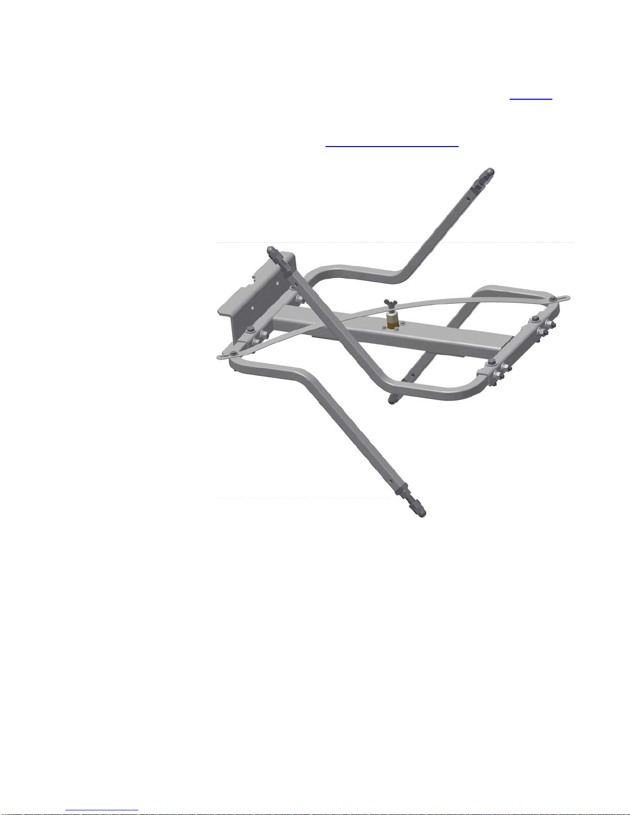
Figure 21. Finished antenna bay
assembly
Bay Assembly (without radomes)
This completes assembly of your antenna bay without radomes (Figure 21 on
page 14).
If your antenna has multiple bays, repeat this chapter for the remaining bays.
Then please proceed to Mounting the Antenna Bay(s) on page 23.
14

Bay Assembly (with radomes)
4 Bay Assembly (with radomes)
Attach the mount
channels to the
radome back half.
Figure 22. Mount channels and
clamp halves to radome
a. Attach a center mount channel (Figure 22, 7) and two end mount channels
(21
) to the radome back half (22), using the threaded rods (2) and M12
hardware (3
b. Loosely attach the clamp halves (25
, 23, 24) as shown.
) to the threaded rods.
15

Bay Assembly (with radomes)
Attach the arms to the
radiator.
Figure 23. Arm hole selection
Figure 24. Position inner arms
NOTE
This step may be made easier by clamping the radiator to a surface or
mounting it temporarily on a vertical pole.
a. (Figure 23) Identify the mounting holes to be used.
CAUTION
Parts 5, with the feedstrap mounting holes, must be mounted diagonally
across from each other as shown.
b. Position the inner arms (Figure 24, 4 and 5) on the radiator (6).
16

Figure 25. Radome, inner arms
to radiator
Bay Assembly (with radomes)
c. Attach the radome assembly (assembled above) and the inner arms (Figure
25, 4 and 5) to the radiat or (6), using M8 hardware (8, 9, 10, and 11), finger-
tight only.
NOTE
The channel of the radiator fits into the rectangular slot in the back of
the radome half.
CAUTION
To ensure proper arm alignment, always tighten the nuts on the vertical
bolts before tightening the horizontal ones.
d. Secure each arm with a vertical M8 bolt and hardware (8, 9, 10, and 11).
Torque in accordance with Table 1
on page 1.
e. Tighten the nuts on the horizontal bolts (Figure 25). Torque in accordance
with Table 1
f. Repeat to attach the other two arms in their correct positions.
.
17

Bay Assembly (with radomes)
Install the feedstrap.
Figure 26. Remove wingnut
Figure 27. Feedstrap to endseal
a. Remove the wingnut (Figure 26, 12), the top lockwasher, and the topmost
flat washer from the endseal (13
b. Using the wingnut, secure the feedstrap (Figure 27, 14) to the endseal.
). Leave the second flat washer in place.
18

Bay Assembly (with radomes)
Figure 28. Feedstrap to arms
c. Using the M5 hardware (Figure 28
to the innermost holes in the arms.
, 15, 16, 17, and 18), secure the feedstrap
Figure 29. Feedstrap ends bent
down
d. (High-band only) Bend the ends of the feedstrap down over the arms to
allow clearance inside the radome (Figure 29
).
19

Bay Assembly (with radomes)
Attach the coax cable.
Figure 30. Form coax cable
CAUTION
Stressing a coax connection after assembly can detune the system.
Therefore, never make a connection and the n bend or twist the cable, or
use the connector to force the coax into shape. Form the cable first,
then attach it to the connector.
CAUTION
The minimum bending radius for 1/2" coax is 3" (8 cm). Do not bend it
too tightly; you may damage it.
a. Form the cable (Figure 30, 19) to the desired shape.
b. Insert the elbow end of the coax feedline cable (Figure 31, 19) in through
the round hole in the back of the radome half (22
of the endseal (13
page 1.
). Torque the cable fitting in accordance with Table 1 on
), and connect it to the base
Figure 31. Attach coax cable to
antenna input.
c. Seal the joint thoroughly with splice tape (20).
20

Bay Assembly (with radomes)
Install the radome
front half.
Figure 32. Radome front half
installation
a. Using the 1/4" hardware (Figure 32, 27), attach the radome front half (28)
to the radome back half (22
b. Using splice tape (Figure 33, 20, provided with the antenna) and Dow
Corning 744 adhesive-sealant (26
).
), seal:
Figure 33. Seal around radome
openings.
• The perimeter of the center mount channel on the back of the
radome, and
• The hole in the radome back half around the coax cable.
21

Figure 34. Finished antenna bay
assembly with radome, back
view
Bay Assembly (with radomes)
This completes assembly of your antenna bay with radomes (Figure 34 on
page 22).
If your antenna has multiple bays, repeat this chapter for the remaining bays.
Then please proceed to Mounting the Antenna Bay(s) on page 23.
22

Mounting the Antenna Bay(s)
5 Mounting the Antenna Bay(s)
Mount the antenna bay
on the tower leg or
pole.
Figure 35. Mount the antenna
bay(s).
NOTE
If the supporting structure is non-metallic (for example, a chimney or a
tree), run a ground cable (customer-supplied) from the antenna mount
to a post driven into the ground.
a. Using the M12 hardware (Figure 35, 3, 23, 24), secure the threaded rods (2)
to the mount channel, with the end of the threaded rod extending
approximately one inch beyond the surface of the channel, as shown.
b. Then use the threaded rods with M12 hardware and clamp half (25
the antenna to the tower leg or pole at the location you marked and cleared
of paint. Do not tighten fully at this time.
) to clamp
23

Figure 36. Mount the antenna
bay(s) (with radomes)
Mounting the Antenna Bay(s)
c. (With radomes only) Similarly, clamp the upper and lower end mount
channels (21
) to the tower leg or pole (Figure 36). Do not tighten fully.
Figure 37. Adjust the heading.
d. (Figure 37) Adjust the antenna heading.
24

Mounting the Antenna Bay(s)
Figure 38. Tighten
mounting
hardware.
e. (Figure 38
threaded rods (2
) Tighten the mounting hardware (Figure , 3, 23, 24) on the
). Torque in accordance with Table 1 on page 1.
f. Retouch the tower paint as necessary.
g. (2-bay or 4-bay) Repeat this chapter for the remaining bays.
25


Connecting the Antenna (single-bay)
6 Connecting the Antenna (single-bay)
Connect the coax
feedline cable.
Figure 39. Secure feedline cable
CAUTION
Stressing a coax connection after assembly can detune the system.
Therefore, never make a connection and the n bend or twist the cable, or
use the connector to force the coax into shape. Form the cable first,
then attach it to the connector.
CAUTION
The minimum bending radius for 1/2" coax is 3" (8 cm). Do not bend it
too tightly; you may damage it.
CAUTION
Do not overtighten the connectors. Overtightening may damage them.
a. Secure the cable (Figure 39, 19) to the mounting pole or tower leg, using tie-
wraps (29
) or customer-supplied cable clamps.
27

Connecting the Antenna (single-bay)
Connect the
transmission line cable.
Figure 40. Transmission line
connection
You need to provide a transmission line cable from your transmitter, terminated with a female 7/16 DIN connector.
CAUTION
The antenna is non-pressurized. If you are using pressurized cable, you
must install a gas stop at the coax cable input.
a. (Figure 40) Connect the transmission line cable to the coax cable input, with
a gas stop if necessary. Torque to 18 - 22 lb-ft (2.4 - 3 Pa). Seal with splice
tape.
b. Secure the transmission line cable to the mounting pole or tower leg, using
customer-supplied cable clamps.
Installation of your Versa2une is complete. Please proceed to Startup.
NOTE
If you have any problems with installation, call Shively and talk with a
designer or Sales.
28

Connecting the Antenna (2 or more bays)
7 Connecting the Antenna (2 or more bays)
Mount the power
divider(s).
Two-bay antenna:
Figure 41. Power divider
mounting (two-bay)
Using two power divider mounting kits (Figure 41, 30), mount the power
divider (31) to the mounting structure with its outlet ports roughly halfway
between the antenna bays. Locate the mounts as close to the ends of the
power divider as you can.
29

Connecting the Antenna (2 or more bays)
Four-bay antenna:
Figure 42. Power divider
mounting (four-bay)
Using two power divider mounting kits (Figure 41, 30), mount the power
divider (32) to the mounting structure with its outlet ports roughly halfway
between the antenna bays. Locate the mounts as close to the ends of the
power divider as you can.
30

Connecting the Antenna (2 or more bays)
Secure the coax
feedline cables.
Figure 43. Secure the feedline
cables
CAUTION
Stressing a coax connection after assembly can detune the system.
Therefore, never make a connection and the n bend or twist the cable, or
use the connector to force the coax into shape. Form the cable first,
then attach it to the connector.
CAUTION
The minimum bending radius for 1/2" coax is 3" (8 cm). Do not bend it
too tightly; you may damage it.
CAUTION
Do not overtighten the connectors. Overtightening may damage them.
a. Connect the input ends of the antenna bay cables (Figure 43, 19) to the
power divider outputs.
b. Secure the cables to the mounting pole or tower leg, using tie-wraps (29
customer-supplied cable clamps.
) or
31

Connecting the Antenna (2 or more bays)
Connect the
transmission line cable.
Figure 44. Transmission line
cable connection
CAUTION
The antenna and power divider are non-pressurized. If you are using
pressurized transmission line cable, it
tion.
a. Connect the transmission line cable from the transmitt er to t he input of the
power divider (Figure 44
, 31 or 32), with an adapter if necessary.
MUST
include a gas stop termina-
b. Secure the transmission line cable to the mounting pole or tower leg, using
customer-supplied cable clamps.
Installation of your Versa2une is complete. Please proceed to Startup.
NOTE
If you have any problems with installation, call Shively and talk with a
designer or Sales.
32

Startup
8Startup
WARNING
Whenever a rigger is on the tower in the area of the antenna, shut off
the signal and lock it off so that it cannot be turned on accidentally. RF
emissions at close range are hazardous.
NOTE
The Versa2une does not require pressurization or purging.
Optimize VSWR.
Figure 45. Apply the signal
(Figure 45) Apply a low-power signal to the antenna and read reflected power
(VSWR). VSWR should be below 1.2:1.
Adjust to minimize
reflected power if
necessary.
Operate.
a. Loosen one jam nut on one arm of one antenna element and lengthen that
arm by 10 mm (3/8"). With personnel clear, check VSWR again.
b. If the VSWR (reflected power) has increased, return that arm to its original
setting. Then shorten ALL arms by 3 mm (1/8").
c. If the VSWR has decreased, return that arm to its original setting. Then
lengthen ALL arms by 3 mm (1/8").
d. Repeat steps a - c until VSWR is below 1.2:1.
e. Secure all the arms by tightening their jam nuts.
Once the antenna has been installed and VSWR has been confirmed, simply
apply the transmitter signal. Don’t exceed the rated power of the antenna.
33


Troubleshooting
9 Troubleshooting
Broad Spectrum RF
Noise
High VSWR
Change in Coverage
This indicates that some component is not in good electrical contact with the
tower. Make sure mounts are tight, that tower paint has been removed from
under the mounts, and that components of other systems are likewise in good
contact with the tower.
This is caused by any factor that changes the impedance match between the
antenna and the transmitter. Look for:
• Defective RF connector. Make sure connectors are in good shape,
and that center pins are not bent over.
• Damage to any antenna components.
• Paint on radiators.
• Ice buildup on radiators.
• Interference from other tower components, especially components
broken by wind or ice.
This may be caused by the same factors that can cause high VSWR. Look for
VSWR changes as well.
Do recognize, however, that apparent changes in coverage may be due to subjective factors or faults of the receiving equipment. Before doing more than
checking the VSWR, be sure that an actual coverage change has occurred.
35


Maintenance
10 Maintenance
WARNING
Whenever a rigger is on the tower in the area of the antenna, shut off
the signal and lock it off so that it cannot be turned on accidentally. RF
emissions at close range are hazardous.
Log
Inspection
Paint
Return Policy
We recommend that you keep a log of VSWR readings and any other performance notes and maintenance history for your antenna. Such a record can be
invaluable for troubleshooting.
Whenever a rigger is on the tower for any reason, it is a good idea to have
him check your antenna for general condition, looseness of connectors and
mounts, and electrical damage.
The radiator should never be painted; this will affect the VSWR.
When returning any material to the factory, be sure to call your salesperson
and obtain an returned materials authorization (RMA) number first. Material
may be refused and sent back to you at your expense if you don’t do this.
37


Parts
11 Parts
Parts list.
Item callouts are consistent across all the illustrations in this technical
sheet.
Table 2. Parts List
Description without radomes with radomes
1
bay2 bays4 bays1 bay2 bays4 bays
1. "Acorn" nut, M12 x
1.75
2. Threaded rod, M12 x
1.75 x 230 mm (9 in)
long
3. Hex nut, M12 x 1.75 15 52 104 26 52 104
4. Arm without feedstrap hole
(marked with 2 UP
sticker)
5. Arm with feedstrap
hole
(marked with 1
DOWN sticker)
4 8 16 4 8 16
6 12 24 10 20 40
2 4 8 2 4 8 99350-G505
2 4 8 2 4 8 99350-G506
NOTE
Shively P/N Appearance (not to scale)
6. Radiator subassembly with end seal
(number stickers
indicate arm loca
tions)
7. Center mount channel
8. Hex bolt, M8 x 1.25
x 45
(in hardware kit)
9. Hex nut, M8 x 1.25
(in hardware kit)
10. Flat washer, M8
(in hardware kit)
-
1 2 4 1 2 4 99350-G502
1 2 4 1 2 4 99351-01
13 26 52 13 26 52
15 30 60 15 30 60
27 54 108 27 54 108
39

Description without radomes with radomes
11. Lock washer, M8
(in hardware kit)
12. Wing nut (shipped
on endseal, item 13)
Parts
Table 2. Parts List (continued)
1
bay2 bays4 bays1 bay2 bays4 bays
15 30 60 15 30 60
1 2 4 1 2 4
Shively P/N Appearance (not to scale)
13. Endseal (part of radi -
ref ref ref ref ref ref
ator)
14. Feedstrap 1 2 4 1 2 4 99350-04
15. Hex bolt, M5 x 0.8 x
3 6 12 3 6 12
35 (in hardware kit)
16. Hex nut, M5 x 0.8
3 6 12 3 6 12
(in hardware kit)
17. Flat washer, M5
6 12 24 6 12 24
(in hardware kit)
18. Lock washer, M5
3 6 12 3 6 12
(in hardware kit)
19. Coax cable section,
1 2 4 1 2 4 99349-G510
10 ft (~3 m) long
with elbow connec
tor on output end
and 7/16 DIN male
connector on input
end
20. Splice tape 1 2 4 1 2 4 92042-01
21. End mount channel n/a n/a n/a 2 4 8 99351-02
22. Back radome half
n/a n/a n/a 1 2 4 99348-01
(cable hole & slot for
radiator channel)
23. Flat washer, M12 6 12 24 18 36 72
24. Lock washer, M12 4 8 16 12 24 48
40

Parts
Table 2. Parts List (continued)
Description without radomes with radomes
1
Shively P/N Appearance (not to scale)
bay2 bays4 bays1 bay2 bays4 bays
25. Clamp half 1 2 4 3 6 12 SCP
26. Dow Corning 744
adhesive-
n/a n/a n/a 1 1 1 DO 88060
sealant, cartridge
27. Radome flange bolt
kit
n/a n/a n/a 1 2 4 93585-G504
(contains 24 1/4-20
bolts, 24 nuts, 48
flat washers, 24 lock
washers)
28. Front radome half
n/a n/a n/a 1 2 4 99348-02
(overlapping flange)
29. Tie-wrap 36 72 144 36 72 144 TY529MX
30. Power divider
0 2 2 0 2 2
mounting kit
31. Power divider, 2-way 0 1 0 0 1 0 99332-G502
32. Power divider, 4-way
0 0 1 0 0 1 99385-G501
(with mounting
clamps)
41

 Loading...