


Circularly Polarized FM
Broadcast Antenna
Model 6814
Instruction Manual
Installation, Operation, &
Maintenance

Congratulations!
Thank you for purchasing one of the finest FM broadcast antennas on the
market today. The Shively Labs Model
of-the-line in its class for its superior performance and durability.
Your purchase is backed by the best technical support in the industry. Shively
is a leading manufacturer in the broadcast industry, providing an extensive
range of antennas, transmission line and components. Our technical staff has
a wealth of experience in the broadcast industry and is standing by to serve
you in any way.
This manual is intended to give you a good basic understanding of your
antenna: its proper and safe installation, startup, and operation, and trouble
shooting and maintenance information to keep it working satisfactorily for
years to come.
Please have everyone involved with the antenna read this
6814 is widely recognized as the top-
manual carefully, and keep it handy for future reference.
Meanwhile, please feel free to contact your sales representative at Shively
Labs at any time if you need information or help. Call or write:
-
Publication No. im-6814 (150601)
2

IMPORTANT
Please read this manual in its entirety before beginning
installation of your antenna!
Failure to follow the installation and operation
instructions in this manual could lead to failure of your
equipment and might even void your warranty!


Table of Contents
Chapter 1 Precautions and Preparation.............................................1
Precautions...........................................................................................1
Receiving..............................................................................................1
Unpacking ............................................................................................1
Checking the system .......................... ........................... ........................2
Chapter 2 Antenna Installation..........................................................3
Precautions...........................................................................................3
Installing the radiators...........................................................................3
Figure 1 Baymount detail................................................................ 3
Figure 2 Radiator installation, exploded view .................................... 4
Figure 3 Flange bolt tightening sequence ......................................... 5
Table 1 Torque Specifications, Flange Bolts...................................... 5
Installation of radomes (if applicable).....................................................5
Figure 4 Radome installation ........................................................... 6
Figure 5 Ground strap installation.................................................... 7
Installing the feedline mounts................................................................7
Figure 6 Common feedline mount configurations ..............................8
Installing the feedline sections...............................................................9
Figure 7 Feedline flange detail......................................................... 9
Installing the transformer .................................................................... 10
Figure 8 Transformer installation, top view............................... ...... 10
Chapter 3 De-Icer Installation (if applicable)..................................11
Precautions.........................................................................................11
De-icer system description................................................................... 11
Dual-setting thermostat ................................................................. 11
Electric power ............................................................................... 11
Figure 9 De-Icer electrical schematic diagram.................................12
Table 2 De-Icer specifications ....................................................... 13
De-icer installation ..............................................................................13
Installing the de-icer harness ......................................................... 13
Figure 10 Bay junction box installation........................................... 14
Installing the thermostat (if applicable)........................................... 14
Table 3 Thermostat readings.................................... ..................... 15
Chapter 4 Startup and Operation.....................................................17
Precautions.........................................................................................17
Pressurization ..................................................................................... 17
Test for leaks................................................................................ 17
Purge the system .......................................................................... 17
Figure 11 Pressurized gas schematic.......................................... .... 18
Table 4 Volume of coax per 1000 feet of length.............................. 19
Leave the system pressurized...................... ...................................19
i

Table of Contents
Impedance trimming..................... ...................................................... 20
Figure 12 Impedance-matching transformer................................... 20
Table 5 Factory control rod settings........................................... .... 20
System sweep (recommended) ............................ ................................21
Checkout............................................................................................ 21
Antenna operation............. ........................... ............................ ........... 22
De-icer system operation..................................................................... 22
Shively Labs de-icer control system ................................................22
Chapter 5 Maintenance ........................................... .........................23
Precautions.........................................................................................23
Maintenance log............................... ................................................... 23
Physical inspection ..................................................................... ......... 23
De-icer check...................................................................................... 24
Paint.................................................................................................. 24
Radiator removal for repair.................................................................. 24
Return policy ......................................................................................24
Troubleshooting.................................................................................. 24
Internal arcing .............................................................................. 24
Broad spectrum RF noise ...................................................... ......... 24
High VSWR at startup or during operation....................................... 25
Erratic VSWR during impedance trimming .......................................25
Change in coverage.......................................................................26
Pressure loss or excessive gas usage ... .............................. ............. 26
Sample maintenance log..................... .. .. .... .. .. .. ... .... .. .. .. .. .... ... .. .. .... .. .. . 27
ii

Precautions and Preparation
1 Precautions and Preparation
Precautions
Receiving
WARNING
Don't expose personnel to the medical hazards of intense radio frequency (RF) radiation. Whenever working on the tower in the area of
the antenna, turn off all transmitters and lock them out so that they can
not be turned on accidentally.
For reference on RF safety, see CFR 29, Section 1910.97, the OSHA standard
for exposure to non-ionizing radiation.
As soon as you receive your antenna,
a. Check to be sure all the material has arrived.
BEFORE
signing for the shipment:
-
NOTE
The box number and the total number of boxes are marked on each box;
for example, “Box 2 of 5” means “box number 2 of a total of five boxes.”
b. Check for evident damage to any of the boxes.
c. If any boxes are missing, or if any are obviously damaged, describe the
problem in a WRITTEN note on the shipping papers BEFORE signing them.
Then call Shively right away, and we’ll do everything we can to correct the
situation.
Important!
Never store the antenna system outdoors, boxed or otherwise. Take
pains to keep the antenna components dry. You will need to purge mois
ture from the interior of the antenna components before applying trans-
mitter power, and purging will be much more time-consuming if the
components get wet.
-
Unpacking
a. Find Box 1; it is marked “Open This Box First.” It contains the transformer
and two copies of the installation drawing. The parts list on one sheet of the
installation drawing shows what box each item is in.
b. Then open the boxes and examine for shipping damages. File any necessary
claims with the carrier immediately.
c. If all the boxes are present and in good condition but material seems to be
missing, please contact Shively Labs immediately, using the telephone or Fax
number on the inside cover of this manual. For the best service, have our
shop order number (S/O) handy; it's in the block at the bottom right corner
of the installation drawing.
d. Along with your antenna you will get a spare parts kit. Place this in a safe
place until it is needed.
CAUTION
All contact surfaces and openings to the interior of the components are
protected from contamination and from physical damage by caps and
plastic bags. Do not remove this protection until ready to connect the
components.
1

Precautions and Preparation
Checking the system
Remember!
It is YOUR responsibility to ensure that your installation meets all appli-
cable codes and the centerline-of-radiation requirements of your FCC
construction permit.
Shively has planned the installation of the antenna based upon information
provided by you. If this information contained errors, the parts and mounting
hardware will have been designed incorrectly and will cause expensive delays
in installation.
Therefore, we recommend that you recheck the installation
parameters during this planning stage.
Check all the parts to be sure that they will fit the tower and each other. Study
the installation drawings carefully to confirm that the information used in
designing the antenna and mounts was, in fact, accurate.
Have a reliable tower person, familiar with antennas and coaxial line, inspect
the tower and review the installation drawings before the full rigging crew
arrives.
If design problems are found, contact Shively Labs immediately. Pay particular attention to:
• Frequency of the antenna.
• Fit of the mounts to the tower members.
• Freedom from interference by gussets, leg flanges, guys and their
attachment points, tower face members, obstruction lights, and
other components.
• Compatibility of transmission line and antenna input terminals.
• Location of the transmission line run relative to the antenna input
terminal.
• Use of non-metallic guy sections on the tower in the region to be
occupied by the FM antenna. Ensure that there are no metal guys
within ten feet (three meters) of any radiator.
• Availability of proper electrical service for de-icers, if applicable.
• The adequacy of the tower structure and guys to carry the windload placed upon them by the antenna, particularly if radomes are
used.
You gave Shively this information at the time of purchase, but a last check at
this time can catch an error, which will be easier to correct before installation
begins.
2

Antenna Installation
2 Antenna Installation
Precautions
Installing the radiators
Figure 1. Baymount detail
WARNING
Don't expose personnel to the medical hazards of intense radio frequency (RF) radiation. Whenever working on the tower in the area of
the antenna, turn off all transmitters and lock them out so that they can
not be turned on accidentally.
It will be easiest to mount the radiators onto the feedline sections before the
feedlines are mounted on the tower.
a. Pair up the feedline sections and the radiator assemblies, using the bay
number stenciled on each piece.
-
CAUTION
To prevent damaging the copper feedline, use clamps rather than
U-bolts, and don’t overtighten.
b. Lay a feedline section horizontally, supported off the ground, with its
baymount flange pointing upward. Secure the feedline section at the brass
end, using clamps, to prevent its turning with the weight of the radiator.
CAUTION
All contact surfaces and openings to the interior of the components are
protected from contamination and from physical damage by protective
covers and plastic bags. Do not remove this protection until ready to
connect the components.
c. Remove the plastic bag and protective cover (see Figure 1) from the
baymount flange on the feedline.
d. Feedline flange hardware and baymount flange hardware are shipped
separately in plastic bags. Each bag contains the hardware for one flange.
O-rings are also shipped in a separate bag.
3

Important
Be very careful not to disturb or damage the feed
strap when handling the
radiator .
Antenna Installation
CAUTION
All O-rings are made of silicone. Do not lubricate them with silicone
grease, as this will soften the O-ring. Use only a light lubricating coat of
O-Lube (provided) or petroleum jelly; too much may hamper electrical
contact and contaminate the interior of the system.
Be sure the O-ring is properly seated in its groove and not pinched
between the flange contact surfaces.
e. Remove the O-ring and coat it lightly with O-Lube (supplied with the
antenna), then reinstall it in the O-ring groove in the flange.
f. Before installing the bay radiator, make sure an inner conductor connector
is in place in the inner conductor of the baymount flange.
CAUTION
Assemble components in accordance with the installation drawing. If you
don’t, the antenna may not perform as expected.
g. Remove the matching radiator assembly from its protective plastic bag.
CAUTION
Be sure the radiator’s inner conductor fits cleanly over the baymount’s
inner conductor connector. If any of the fingers of the connector are
forced outside the radiator’s inner conductor (a "split bullet"), this will
cause arcing and damage to the antenna.
h. Align the radiator with the baymount flange as shown in Figure 2, with the
top pointing toward the nearby feedline flange. Carefully place the radiator
into position over the flange studs and inner conductor connector.
Figure 2. Radiator installation,
exploded view
i. First snug the flange bolts in the sequence shown in Figure 3, then tighten
them in accordance with Table 1
.
4

Figure 3. Flange bolt tightening
sequence
Antenna Installation
Table 1. Torque Specifications, Flange Bolts
Installation of radomes
(if applicable)
Transmission Line
Size
1-5/8" 5/16-18 12 ft-lb 16 N-m
2-1/8" 3/8-16 21 ft-lb 28 N-m
3-1/8" 3/8-16 21 ft-lb 28 N-m
4-1/16" 3/8-16 21 ft-lb 28 N-m
j. Clamp the mounting saddle to the feedline, using a clamp.
Bolt Size Torque
CAUTION
Feedstrap orientation is critical to performance. In general, the feedstraps in a full-wave-spaced antenna will all be oriented the same, while
those in a half-wave-spaced antenna will alternate.
Install each radiator
in accordance with its stenciled bay numbers and its "up-arrow" sticker.
k. Determine what, if any, icing protection your antenna has.
• If you antenna has de-icers, go to Chapter 3.
• If your antenna has radomes, continue.
If your system includes radomes, you can most easily install them on the
ground at this time. See
a. Each radome is shipped partially assembled on its own pallet. Disassemble
the radome halves and the radome mount.
b. Identify the top (wide mating flange) and bottom (narrow mating flange and
drain holes) radome halves.
Figure 4 on page 6.
NOTE
The feedline comes with a 20-inch-long extension in place (see Figure
2). This extension, in effect, moves the feedline joints outside the
radome, and thus allows you to mount the radome on the ground. You
should treat the feedline with its extension as a single unit.
c. Remove the closure plate bolts where the mount will slip under the closure
plate. Loosen the other closure plate bolts and leave the closure plates in
place on the radome.
d. Place four clamps loosely around the feedline, tw o above and two below the
baymount flange. Mounting the saddle is easier if the clamps are in place
first.
e. Locate the mount on the feedline as shown, centered exactly opposite the
baymount flange (use a ruler or a level to center it). The uppermost part of
the mount should be one inch from the flange of the feedline extension.
5
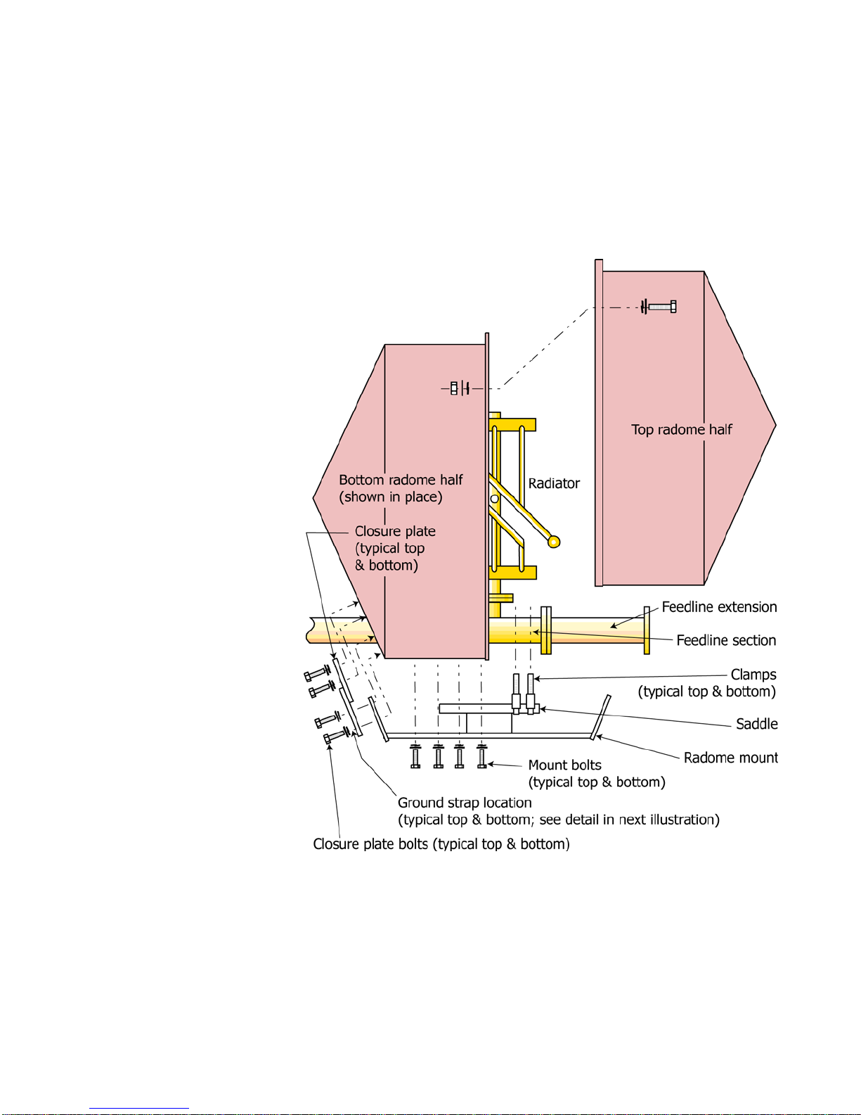
Figure 4. Radome installation
Antenna Installation
f. Using the four clamps, clamp the mount saddle to the feedline.
g. Place the top radome half over the radiator and into the mount, slipping the
end of the mount under the closure plate.
h. Place the bottom radome half over the radiator and feedline and into the top
radome half, inserting its mount into its closure plate.
i. Bolt the radome halves loosely to the mount with the mount bolts
(3/8" with lock washers and flat washers).
j. Fasten the two radome halves together with the 1/4" flange hardware,
starting at the feedline side and working around both sides to the outer edge.
Tighten the flange hardware.
NOTE
You may have to squeeze the radome flanges together slightly with a
clamp to start the nuts. Get all these nuts and bolts in place, then
tighten them.
6
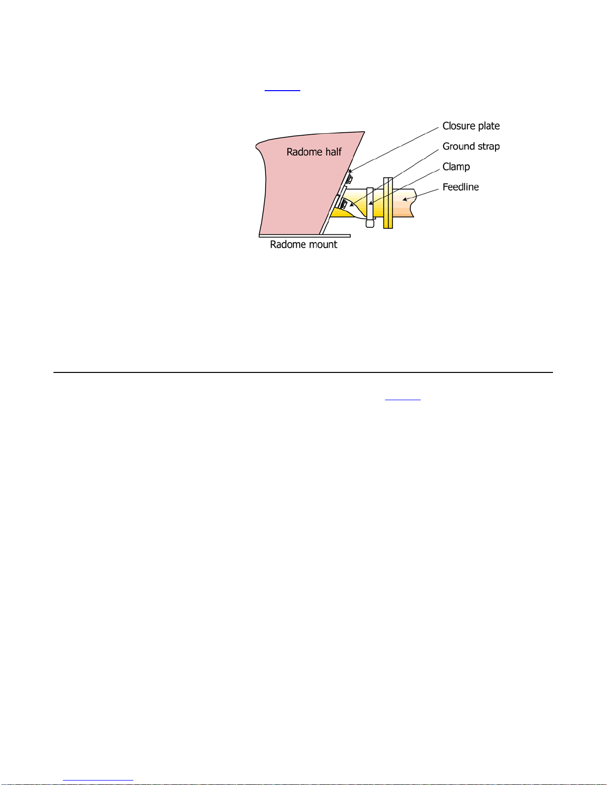
Figure 5. Ground strap
installation
Antenna Installation
k. Twist and clamp the loose ends of the ground straps to the feedline, as
shown in Figure 5
feedline.
l. Tighten the closure plate bolts and the mount bolts, securing the bolted ends
of the ground straps as well.
. This will prevent arcing between the mount and the
Important
Be very careful to seal the joint completely. If water enters the radome,
the antenna will not perform as expected, and may cause damage to
your entire system.
m. Seal the closure plates and the joint where the radome encircles the
baymount with the silicone sealant supplied with the antenna.
Installing the feedline
mounts
Feedline mounts vary from installation to installation, to accomodate various
tower and mounting pole requirements.
figurations. Your feedline mounts may be one of the common designs shown;
if they are not, they will be shown in detail on your installation drawing.
Before you begin installation, study the mounts, the mounting tower leg(s) or
pole, and your installation drawing carefully, establishing which mount(s) will
be used for each component.
a. On the tower, starting at the top, use a steel measuring tape to find the
location of each bay in accordance with the installation drawing. Mark the
mount locations.
b. Mark the specified location of any accessory mounts, such as for the
transformer or special coax input line sections, to make sure they will fit as
planned.
c. Watch carefully for any interferences by tower members or guy wires which
were not accounted for in the design.
Figure 6 shows several common con-
7

Figure 6. Common feedline
mount configurations
Antenna Installation
Mounts may vary from bay to bay, especially on tapered towers or where
tower obstructions exist. See your installation drawing for your mount
configuration and special requirements, if any.
CAUTION
If you don't get good electrical contact between the mounts and the
tower, the antenna may not perform as designed, and may produce
stray signals that will interfere with other services on the tower.
8

Antenna Installation
d.
Where the mounts will be in contact with the tower or pole, scrape the tower
paint away to ensure good electrical contact.
e. Secure the feedline mounts to the tower leg(s) or mounting pole using
U-bolts.
f. When all mounts are in place, sight along them vertically and align them
before finally tightening the hardware.
g. Touch up any exposed metal on the tower or pole.
If any problems appear during this process, please call Shively Labs and dis-
cuss them with the installation designer.
Installing the feedline
sections
Figure 7. Feedline flange detail
Important!
To avoid damage to the
antenna, always lift, position, and attach each section individually. Never try
to transport connected
feedline sections! This rule
is often violated and is frequently the cause of
expensive damage to feedline.
CAUTION
Feedline flanges are match-marked. Assemble components in accor-
dance with their match-markings (see Figure 7) and the installation
drawing. If you don’t, the antenna may not perform as expected.
CAUTION
The feedline inner conductors include "bullet guides" (see Figure 7) to
help prevent split bullets. Be sure the bullet guides are in place before
assembly.
a. Install the feedline sections, transforme r, and other components carefully, in
accordance with your installation drawing and the illustrations in this
chapter.
b. Secure the feedline to the mount saddles using the clamps provided
(generally, two clamps on a 6"-long saddle and 4 clamps on a 12"-long
saddle). To align the antenna to the proper azimuth, match the stenciled line
on the feedline with the weld dot on the top edge of the mount saddle.
CAUTION
To prevent damage to feedline, be sure the feedline mount saddles are
located against the brass portion of the feedline, and position the clamp
screw housings over the saddles, not against the feedline.
9

Antenna Installation
c. As each feedline section is lifted into place, remove the plastic bags and
protective covers from the flanges and install an O-ring, lubricating it with a
light coat of petroleum jelly (provided with the antenna) Tighten the flanges
in accordance with Figure 3
d. Secure each feedline section to its mount before installing the next section.
and Table 1 on page 5.
Installing the
transformer
Figure 8. Transformer
installation, top view
One of the unique features of Shively Labs antenna systems is the adjustable
impedance-matching transformer provided with the antenna. It allows the
installer to compensate for changes in the input impedance caused by the
installation (tower, conduit, ladder, etc.).
NOTE
The transformer may be oriented in whichever direction you wish (see
Figure 8). Make it easy for yourself to reach for adjustment at startup.
Install the transformer between your transmission line and the feedline. The
male end (with the inner conductor connector in place) always goes at the
top. Transformer mounts are generally similar to feedline mounts and should
be installed in the same manner.
10

De-Icer Installation (if applicable)
3 De-Icer Installation (if applicable)
Precautions
WARNING
Installation should be performed only by personnel
experienced in RF systems, qualified in electrical work, and familiar
with this equipment.
De-icer system
description
WARNING
Don't expose personnel to the medical hazards of intense radio fre-
quency (RF) radiation. Whenever working on the tower in the area of
the antenna, turn off all transmitters and lock them out so that they can
not be turned on accidentally.
-
CAUTION
All parts of the de-icer system within approximately 20 feet (6 meters) of
any radiator must be shielded from RF energy, and the entire outdoor
portion of the system must be made waterproof.
CAUTION
An improperly installed de-icer can overheat and damage your antenna.
The de-icer system consists of the heating elements in the bays, their branch
cables, and the main harness. The main harness consists of a bay junction box
for each antenna bay, interbay cables, and a "pigtail" of wires about 10 feet (3
meters) long which you will connect to the tower junction box you are to pro
vide. The following will help in installation:
• System electrical schematic: Figure 9 on page 12.
• Electrical specifications: Table 2 on page 13.
• Bay junction box: Figure 10 on page 14.
• Thermostat readings: Table 3 on page 15.
-
Dual-setting thermostat
Electric power
Your system may also include specially-ordered items, such as a groundmounted main control box, a power cable extending up the tower, or a towermounted dual-setting thermostat.
CAUTION
Remember that conditions may be favorable for icing on the tower, even
if they are not on the ground.
Shively Labs de-icers are designed to prevent ice from forming on antenna
elements and are not designed to melt ice that has already formed. For this
reason, Shively Labs recommends that the syst em be installed with a towermounted dual-setting thermostat assembly (Shively Labs Model 55522-G502)
and de-icer control box (Shively Labs Model 94068) that ensure the de-icers
are operated in the temperature range ice is most likely to form.
The de-icer system requires 220 VAC, 50 - 60 Hz., single-phase. Table 2 on
page 13 shows approximate heater leg resistances and current draw, respectively, measured at the tower junction box (Figure 9 on page 12).
11

Figure 9. De-Icer electrical
schematic diagram
NOTE
Customer-supplied items
are shown in broken lines.
De-Icer Installation (if applicable)
NOTE
A liquid-tight conduit connector (3/8" conduit size
by 1/2" hub size) for the
harness entry to the
tower junction box, is
packed loose with the deicer harness.
NOTE
Shively recommends the
use of shielded braided
polyethylene-covered wire
or rubber-sheathed flexible metal conduit or rigid
conduit and weather-tight
fittings at all junctions.
12

De-Icer Installation (if applicable)
Table 2. De-Icer specifications
1-Bay, single circuit 55 2.0 46 2.4
2-Bay 27 4.0 23 4.8
3-Bay 18 6.0 15 7.2
4-Bay 14 8.0 11 9.7
5-Bay 11 10.0 9 12.1
6-Bay 9 12.0 8 14.5
7-Bay 8 14.0 7 16.9
8-Bay 7 16.0 6 19.3
10-Bay, each of 2 circuits 12 10.0 8 12.1
12-Bay, each of 2 circuits 8 12.0 6 14.5
14-Bay, each of 2 circuits 8 14.0 8 16.9
16-Bay, each of 2 circuits 8 16.0 4 19.3
De-icer installation
High-Band
(98.0-108.0 MHz
Heater Leg
Resistance,
Heater Leg
(T1 or T2)
Current Draw,
amps
Low-Band
(88.0-97.9 MHz)
Heater Leg
Resistance,
Heater Leg
(T1 or T2)
Current Draw,
amps
Installing the de-icer
harness
a. Install the main de-icer harness with its bay junction boxes as shown in
Figure 9
bay’s de-icer pigtail to the main harness in that bay’s junction box as shown.
on page 12 and Figure 10 on page 14. Connect the leads from each
CAUTION
It is important to ground both the tower junction box and the control
box, as shown in the schematic diagrams.
b. Furnish a tower junction box as shown schematically in Figure 9 to connect
the antenna’s de-icer harness to the main power.
c. Using tie-wraps, secure the entire length of the de-icer harness to the RF
feedline at about 24" (60 cm) intervals. Run the ten-foot de-icer pigtail along
a feedline mount to the tower junction box and secure it to the mount and
the tower.
13

Figure 10. Bay junction box
installation
CAUTION
Shively Labs's de-icer
control box, Model 94068,
is designed for interior
installation only.
NOTES
Wire nuts, cover with
screws, and gaskets, and
tie-wraps are provided
with the de-icer cable harness.
De-Icer Installation (if applicable)
The antenna pigtail
grounds to the box via its
braided sheath.
The ground screw may be
in a different location from
that shown.
Installing the thermostat
(if applicable)
If you are using a thermostat, you may locate and mount it at your discretion.
We recommend mounting it as close as practical to the antenna.
CAUTION
When testing the thermostat, be sure to have one or both thermostat
leads disconnected b efore taking resistance readings. Ot herwise, read
ings may be affected by other components.
a. Before you connect the thermostat, measure the resistance across the
thermostat circuit and from it to ground to ensure that there are no short-
circuits. Thermostat readings should be as shown in Table 3
b. Mount the thermostat near the antenna and connect the thermostat leads to
points S1 and S2 in the control box as shown in the schematic diagram,
Figure 9
on page 12.
on page 15.
-
14

De-Icer Installation (if applicable)
Table 3. Thermostat readings
Reading
Location
Leg-to-
Ambient
Temperature
Any Defective thermo-
Ground
Leg-to-Leg Above about 38°
F(3.3° C)
Between about 10°
and about 38° F (-
6.7° to 3.3° C)
Below about 10° F
(-6.7° C)
Resistance =
0 ohms
(short circuit)
stat or shorted
leads
Defective thermo-
stat or shorted
leads
OK Defective thermo-
Defective thermo-
stat or shorted
leads
Resistance =
infinite ohms
(open circuit)
OK
OK
stat or broken leads
OK
15


Startup and Operation
4 Startup and Operation
Precautions
Pressurization
Test for leaks
Pressure Correction:
where PC = corrected
final pressure, psig
= final pressure as
P
R
read, psig
T
= beginning tempera-
1
ture, degrees F.
= final temperature,
T
2
degrees F.
Important
Shively Labs will not accept responsibility for antenna failure aft er oper a-
tion without proper purging or positive pressure of dry air or dry nitro-
gen.
After the antenna is installed and all lines are connected, it is necessary to
check the system for leaks, purge with dry gas (cylinder dry nitrogen or air
from a compressor-dehydrator) to remove all moisture, and leave the system
pressurized with dry gas to avoid future infiltration of moisture. These steps
must be taken before RF power is applied to the system.
CAUTION
When pressurizing the system, never use a "garage" air compressor, as
it will not clean the air and will blow both moisture and contaminants
such as oil and graphite into the coaxial system.
a. Connect a source of dry gas (cylinder nitrogen or air from a compressor-
dehydrator) to the system as shown in Figure 11
on page 18.
CAUTION
Be sure to use a good quality pressure gauge which will read accurately
in the 5 - 20 psig (35 - 135 kPa) range; don't depend on the cylinder
gauge, which will not be accurate at a low pressure.
b. Pressurize the system to seven (7) psig, then close the shutoff valve. Give
the system one half hour to stabilize, then record the pressure and the
temperature.
c. Wait twenty-four hours, then read the pressure and the temperature again
and use the pressure correction formula at left to obtain a corrected pressure
for comparison.
d. If the system loses pressure at an unacceptably high rate, re-pressurize it,
leaving the gas supply on. A rule of thumb is that the final pressure should
not be less than half the initial pressure after twenty-four hours.
e. Find the leak(s), using a leak detector or soap bubbles. (The most common
cause of leakage is an O-ring pinched in a flange.)
f. Correct any leaks that are found. Then repeat the leak test until the results
are satisfactory.
Purge the system
All pressurized Shively Labs antennas have a pressure relief valv e at the top of
the feedline (center-fed feedlines have a relief valv e at each end). This v alve is
set to open at about 10 psig. So, to purge the system, it is not necessary to
send a worker to the top of the antenna to open a valve or loosen a flange.
Simply raise the internal pressure enough to open the relief valve. When the
purge is complete, lower the pressure and the valve will close.
When the system is new, and any time that it has been opened, it must be
purged with dry gas before operation to eliminate moisture. The dry gas used
may be dry cylinder nitrogen or air from a compressor-dehydrator.
17

Figure 11. Pressurized gas
schematic
Startup and Operation
CAUTION
If all moisture is not
removed from the interior of the system, it will
condense when the
weather cools. The resulting water will cause arcing and permanent
destruction of the coaxial
system, including the
transmitter output network.
Purge your system as follows:
a. If you have any liquid water in your transformer or your transmission line,
use a vacuum pump to dry the transmission line and transformer. Apply as
much vacuum as you can to the system and hold the vacuum for 8 hours.
This should remove any liquid water. [A vacuum pump can be rented or
borrowed from a refrigeration contractor.]
b. Determine how wet the system is, and thus how much purging will be
required. If a system of rigid line carefully protected from weather and
assembled in dry weather is average, a system exposed to moisture during
storage or installation will be relatively wet. New semi-flex transmission line,
delivered pressurized with dry gas, will be relatively dry; used semi-flex will
be extremely wet.
18

Startup and Operation
c. Determine the volume of dry gas to use for the purge. Table 4
approximate volumes inside various coax sizes. Add the length of the
antenna to the length of the transmission line to determine the overall length
of the system. You may ignore the volume inside the radiators. We suggest
three volume changes of dry gas for an "average" system.
Table 4. Volume of coax per 1000 feet of length
Coax Size Volume
1-5/8" 13 cu ft. (0.37 m3)
3-1/8" 50 cu. ft. (1.4 m3)
4-1/16" 90 cu. ft. (2.6 m3)
6-1/8" 200 cu. ft. (5.7 m3)
9-3/16" 450 cu. ft. (13 m3)
shows
NOTE
A standard nitrogen cylinder (9 inch diameter by 55 inches tall) contains
3
about 200 cubic feet (5.7 m
) of gas.
CAUTION
Do not raise pressure over 20 psig (~135 kPa), even briefly. Note that it
takes time for the entire system to fill with the new pressure and the
pressure gauge to stabilize.
d. Connect a source of dry gas (cylinder nitrogen or air from a compressor-
dehydrator) to the system as shown in Figure 11
12 or 13 psig (83 - 90 kPa).
. Raise the gas pressure to
Leave the system
pressurized
CAUTION
You must blow dry gas
The gas
e. If the relief valve has opened, the nitrogen cylinder will slowly drain or the
compressor-dehydrator will not shut down.
After completion of the purge, reduce the supply pressure to about 5 to 7 psig
(35 to 48 kPa), allowing the pressure relief valve to close and seal the system.
After the pressure has stabilized, keep careful note of cylinder pressure or
compressor-dehydrator running time, t o be sur e that no large leaks have been
overlooked. This is especially important immediately after installation or any
subsequent opening and reassembly.
volume
accomplishes the purge.
through
the system, not just maintain a pressure.
19

Impedance trimming
Figure 12. Impedance-matching
transformer
Startup and Operation
The transformer has been factory-adjusted to 50 ohms at your frequency. You
will find a scribed line on each control rod shaft. It can be operated at that
setting, but it will give optimal performance on your tower if you readjust it
after installation.
Adjust the transformer as follows:
a. Loosen the clamps on the control rods enough to allow the rods to move.
b. Grasp either control rod and slide it in or out about 1/4 inch or 6 millimeters.
It will move stiffly because of O-ring friction.
c. Read the VSWR. If the reading went down, move the control rod again in the
same direction. If the VSWR went up, move the same rod in the opposite
direction.
Table 5. Factory control rod settings
Nominal
Transformer Size
1-5/8” 3-3/4" ± 1/16" (95 ± 1.5 mm)
3-1/8" 2-3/4" ± 1/16" (69 ± 1.5 mm)
4-1/16" 3-1/2" ± 1/16" (89 ± 1.5 mm)
d. Keep adjusting the same rod until no further improvement is seen. Adjust
the second rod in the same manner. If you get "lost," return both rods to the
factory setting (Table 5
e. Return to the first rod, and so forth, until you have the lowest possible VSWR
or return power reading. This is the optimal transformer setting.
) and start over.
Factory Control Rod Setting
(
Figure 12 on page 20)
20

Startup and Operation
f. VSWR at this point should be below 1.10 : 1. If it is not, call Shively Labs to
help identify the problem.
g. When you have set the transformer, use a sharp point to scribe the shaft
where it leaves the flange collar.
h. Record the control settings of the two control rods and file this information
with this manual for future reference.
i. Tighten both hose clamps. If the hose clamps are left loose, vibration may
change the adjustments.
System sweep
(recommended)
Checkout
Shively Labs strongly recommends that you perform a system sweep of your
transmission line and antenna while you have the installation crew on site.
Should any problems arise later with your antenna, it will be extremely helpful
to know what the system’s characteristics were when it was new. We recom
mend you perform a system sweep after installation.
-
CAUTION
A high voltage standing wave ratio (VSWR) may indicate damaged trans-
mission line or incorrectly assembled components. This condition will
cause serious damage to your equipment when full power is applied.
Many riggers can sweep your system after installation or recommend a con-
tractor to perform it. Alternatively, Shively Labs makes available instructions
for system sweep on our Web site, www.shively.com.
Before beginning checkout of the antenna system, be sure the following items
have been done:
• The antenna system has been installed in accordance with this
manual and the installation drawing.
• The de-icer system, if purchased, has been checked out in accordance with Chapter 3.
• All radiators are operating; impedance has been trimmed, and
VSWR is low.
• The transformer settings and initial characterization data have been
recorded.
• The system is gas-tight and purged.
Check the system out as follows:
a. Bring up RF power slowly and observe transmitter readings, stability, and
general operation.
b. Run at about half power for at least an hour, reading forward and reflected
power, stability, etc.
c. If the system is stable and seems to be operating properly, bring it up to full
power. Take initial readings, and repeat the readings periodically.
d. Performance readings should not change, and there should be no evidence
of heating in the antenna system.
If any problem is found, fix it now. Call Shively Labs if you need help or
advice.
21

Startup and Operation
Antenna operation
De-icer system
operation
Shively Labs de-icer control
system
CAUTION
Don't exceed the rated power capacity of the antenna.
To obtain the best performance and dependabi lity, read and follow the maintenance and troubleshooting recommendations in Chapter 5 of this manual.
CAUTION
Don't leave the de-icer on for extended periods when the weather is
above 50° F (10° C); doing so may shorten the life of the heater ele
ment(s).
There is a generous margin of safety built into the de-icer system, and operation for prolonged periods below 50° F (10° C) will not harm the system. If
icing conditions are expected, the heaters should be turned on in advance as a
preventive measure. It is much easier to prevent ice formation than to remov e
a heavy coating.
If you have the Shively Labs de-icer control box and dual-setting thermostat,
you have the choice of manual or automatic operation. There are three switch
settings: AUTOMATIC, OFF, and MANUAL.
• When the switch is set to AUTOMATIC, the thermostat turns the
heaters on and off according to the temperature.
• When the switch is set to OFF, the thermostat is overridden and the
heaters will stay off no matter what the temperature.
• When the switch is set to MANUAL, the thermostat is overridden
and the heaters will stay on no matter what the temperature.
-
22

Maintenance
5 Maintenance
Precautions
WARNING
Maintenance should be
performed only by personnel experienced in RF
systems and familiar with
this equipment.
WARNING
Don't expose personnel to the medical hazards of intense radio frequency (RF) radiation. Whenever working on the tower in the area of
the antenna, turn off all transmitters and lock them out so that they can
not be turned on accidentally.
-
Important
When you have had the system open for repair, you must purge it again
as described in
system under power until you are sure all the moisture has been purged
from it. You can do permanent damage to the entire system, including
the transmitter.
Purge the system on page 17. Never begin o pe rating the
CAUTION
When removing or replacing radiators on the tower, never let the weight
of the radiator hang on the inner conductor without bolting. This will
damage the connector and possibly the inner conductor itself. Support
the weight of the radiator until the flange bolts are tightened.
CAUTION
All O-rings are made of silicone. Do not lubricate them with silicone
grease, as this will soften the O-ring. Use only a light lubricating coat of
O-Lube (provided) or petroleum jelly; too much may hamper electrical
contact and contaminate the interior of the system.
Be sure the O-ring is properly seated in its groove and not pinched
between the flange contact surfaces.
Maintenance log
Physical inspection
Important
Give your antenna a full
inspection at least once
per year!
Shively recommends that you keep a maintenance log; in it record performance parameters such as readings of VSWR and de-icer current draw.
Such a log can be invaluable in spotting and identifying problems. Sample
maintenance log on page 27 shows a suggested log form you may use if you
like.
The antenna system should operate for years if properly installed and maintained. Shively Labs recommends that as a minimum, the antenna should be
physically inspected
In addition, inspect the antenna after severe weather events, and after climbers have been on the tower working on equipment above the antenna.
In addition to checking the general condition of the antenna and coax:
• Replace dented, broken or bent components.
• Inspect radomes for cracks and plugged drain holes.
• Re-tighten all hardware, clamps, and U-bolts to installation specifications.
• Inspect clamps and U-bolts carefully for signs of wear or fatigue
caused by vibration or tower movement.
at least once a year
.
23

Maintenance
De-icer check
Paint
Radiator removal for
repair
Return policy
Periodically (we suggest at the end of each winter season), check the condition of the de-icer wiring with an ammeter; compare the legs of the system
with each other and with initial readings taken at installation. If an ammeter is
not available, resistance readings of each leg will suffice.
The radiators should never be painted (a coating of paint affects VSWR), and
they need no surface protection, since they are made of copper and brass.
This includes Teflon or other "ice-prevention" coatings.
It is not necessary to paint the feedline, although no harm will result from
doing so.
In some cases, a damaged radiator may be removed and returned to the factory for repair. The system can then be sealed with a pressure cap, and operation of the antenna can resume with proportional power reduction and
increased VSWR.
See the Shively Web site, www . shiv ely.com, for part numbers of pressure caps
and other components.
Operating with missing bays may not be possible with some transmitters or
antennas that have only a few bays, since some transmitters will not operate
into loads with high VSWRs. Contact Shively Labs before attempting this pro
cess.
When returning any material to the factory, be sure to call your salesman and
obtain an returned material authorization (RMA) number first. Use this num
ber in all correspondence. This number helps us to track your returned item. It
will expedite repair or replacement and prevent loss of your material.
-
-
Troubleshooting
Internal arcing
Broad spectrum RF noise
Cantact Shively Labs if necessary to help find the cause of your problem. Outside of 8:00 AM to 5:00 PM Eastern Time, call (207) 329-5118.
The following may cause internal arcing:
• Physical damage to transmission line, feedline, or radiators. Damage may have been caused by ice, lightning, tower work, or many
other factors. Damage may cause arcing directly or by allowing
water inside the system.
• Missing or misaligned O-ring, if the system has been opened
recently.
• Loss of pressurization.
This indicates that some metal components are not in good electrical contac t
with the tower. First, check your antenna mounts, then other tower compo
nents, to be sure that the tower paint has been scraped away and that all
mounting hardware is tight.
Any metal part in poor contact with the tower will constitute a non-linear junction and cast a broad-spectrum signal. This includes antennas, transmission
line, mounts, ladders, and other electrical components.
-
24

Maintenance
High VSWR at startup or
during operation
High VSWR (Voltage Standing Wave Ratio) is caused by any factor which
changes the impedance match between the transmitter and the antenna sys
tem.
The following may cause high VSWR:
• Wrong antenna for the application and frequency. Make sure the
antenna is the correct frequency.
• Split bullet in the transmission line or in the baymount (see Figure 1
on page 3). A split bullet is an inner conductor connector misaligned such that one or more of its contact arms is stuck outside
the conductor instead of inside. (A missing bullet will cause infinite
VSWR.)
• Mismatched assembly of the antenna. The bays must be paired
properly with their respective feedline sections, and the assembly
must be exactly as shown in the installation drawing.
• Radiators out of sequence (especially on a c enter -f ed, null-filled, or
half-wave-spaced system).
• Damaged feed strap(s) on a radiator. The feed strap is the brass
strip that extends back from the end seal. The length, angle, and
straightness of the feed strap are critical to the radiator's perfor
mance.
• Components of other services that have entered the RF field (later
installations or broken components).
-
-
Erratic VSWR during
impedance trimming
• Physical damage to the transmission line, feedline, or radiators.
This may be from ice, lightning, tower work, or any other source.
• Paint applied to the radiators, possibly during a recent tower painting.
• Failure of de-icers, causing excessive ice buildup on one or more
radiators.
• Domes missing from vertical arms. An overheating de-icer can melt
the solder from domes, spacers, and bushings at the ends of the
vertical arms.
If VSWR readings during transformer adjustment as described in Impedance
trimming on page 20 do not respond reasonably consistently to transformer
adjustments, then either there is residual water in the transformer, or the
transformer is damaged.
Follow this sequence of actions:
a. Repeat the purging process as described in Purge the system on page 17.
b. Try again to trim impedance.
c. If VSWR is still erratic, Your transformer is probably damaged. Contact
Shively Labs.
25

Maintenance
Change in coverage
Pressure loss or excessive
gas usage
Changes in broadcast coverage may be caused by the same factors that produce VSWR changes. If coverage seems to have changed, look for VSWR
changes and use
troubleshooting.
It is important to recognize, however, that apparent changes in coverage may
be due to subjective factors or faults of the receiving equipment. Before doing
more than checking the VSWR, be sure that an actual coverage change has
occurred.
Failure to hold pressure may be caused by the following:
• O-ring missing or poorly installed in transmission line, feedline, or
• Leaky end seal (see Figure 2 on page 4).
• Loose connecting hardware between line segments or between the
• Mechanical damage to transmission line, transformer, or antenna.
High VSWR at startup or during operation on page 25 for
baymount flange.
baymount and the radiators.
Check for leaks using soap solution.
26

Sample maintenance
log
Maintenance
DATE DE-ICER CURRENT
(or resistance)
BLACK
(b-neut)
NEUT
(red-bl)
(r-neut)
RED
VSWR GAS
PRESS
OBSERVATIONS
Visual Inspection of Antenna, Obstruction
Lighting; Hardware Checked; Tower Repairs
Accomplished; etc.
27

 Loading...