


Circularly Polarized FM
Broadcast Antenna
Model 6812B
Instruction Manual
Installation, Operation, &
Maintenance

Congratulations!
Thank you for purchasing one of the finest FM broadcast antennas on the
market today. The Shively Labs Model 6812B is widely recognized as the topof-the-line in its class for its superior performance and durability.
Your purchase is backed by the best technical support in the industry. Shively
is a leading manufacturer in the broadcast industry, providing an extensive
range of antennas, filters, transmission line and components. Our technical
staff has a wealth of experience in the broadcast industry and is standing by
to serve you in any way.
This manual is intended to give you a basic understanding of your antenna:
its proper and safe installation, startup, and operation, and troubleshooting
and maintenance information to keep it working satisfactorily for years to
come.
Please have everyone involved with the antenna read this manual care-
fully, and keep it handy for future reference.
Meanwhile, please feel free to contact your sales representative at Shively
Labs at any time if you need information or help. Call or write:
Publication No. im6812B (170516)
2

IMPORTANT
Please read this manual in its entirety before beginning
installation of your antenna!
Failure to follow the installation and operation
instructions in this manual could lead to failure of your
equipment and might even void your warranty!


Table of Contents
Chapter 1 Precautions and Preparation ............................................. 1
Precautions........................................................................................... 1
Check the System ................................................................................. 1
Storage prior to installation .................................................................... 1
Bay spacing .......................................................................................... 2
Table 1 Bay spacing chart ............................................................... 2
Bolt tightening ...................................................................................... 2
Table 2 Torque specifications .......................................................... 2
Chapter 2 Antenna Installation.......................................................... 3
Precautions........................................................................................... 3
Installing the support pipe ..................................................................... 3
Figure 1 Support pipe installation .................................................... 3
Table 3 Side-mounted support pipe standoff from tower ................... 3
Installing the radiators........................................................................... 4
Figure 2 Formed mount channel ...................................................... 4
Figure 3 Installation of radiator without radome, exploded view......... 5
Figure 4 Radome backplate installation ............................................ 5
Figure 5 Installation of radiator with radome, exploded view ............. 6
Installing the interbay cable harness....................................................... 6
Figure 6 Installation of top and bottom bays .................................... 7
Figure 7 Wrapping and securing the interbay cables ......................... 8
Figure 8 Proper and improper application of splicing tape.................. 9
Chapter 3 Installing the De-icer System (if applicable)................... 11
Precautions......................................................................................... 11
De-icer system description ................................................................... 11
Figure 9 De-Icer electrical schematic diagram................................. 12
Table 4 De-Icer specifications ....................................................... 13
De-icer installation .............................................................................. 13
Figure 10 Bay junction box installation ........................................... 14
Table 5 Thermostat readings......................................................... 15
Chapter 4 Startup and Operation .....................................................17
Precautions......................................................................................... 17
The antenna ....................................................................................... 17
The de-icer system.............................................................................. 17
Chapter 5 Maintenance and Troubleshooting .................................. 19
Precautions......................................................................................... 19
Maintenance log.................................................................................. 19
Physical inspection .............................................................................. 19
Paint .................................................................................................. 19
Radome removal and reinstallation ....................................................... 19
Return policy ...................................................................................... 20
Troubleshooting .................................................................................. 20
Sample maintenance log...................................................................... 22
i


Precautions and Preparation
1 Precautions and Preparation
Precautions
Check the System
WARNING
Don't expose personnel to the medical hazards of intense radio frequency (RF) radiation. Whenever working on the tower in the area of
the antenna, turn off all transmitters and lock them out so that they can
not be turned on accidentally.
For reference on RF safety, see CFR 29, Section 1910.97, the OSHA standard
for exposure to non-ionizing radiation.
-
CAUTION
It is YOUR responsibility to ensure that your installation meets all applicable codes and the centerline-of-radiation requirements of your FCC
construction permit.
Check the parts to be sure that they will fit the support pipe. Have a reliable
tower person, familiar with antennas and coaxial line, inspect the tower and
review the installation drawings before the full rigging crew arrives. If design
problems are found, contact Shively Labs immediately.
Pay particular attention to:
• Frequency of the antenna.
• Freedom from interference by gussets, leg flanges, guy wires and
their attachment points, tower face members, obstruction lights,
and other components.
• Compatibility of coax connectors and antenna input terminals.
• Use of non-metallic guy sections on the tower in the region to be
occupied by the FM antenna. Ensure that there are no metal guy
wires within ten feet (three meters) of any radiator.
• Proper electrical service for antenna deicers, if applicable.
Storage prior to
installation
• The adequacy of the tower structure and guy wires to carry the
windload placed upon them by the antenna, particularly if radomes
are used.
Keep the antenna system dry. Never store it outdoors. If the antenna gets
wet, you will need to dry it before applying transmitter power.
1
Precautions and Preparation
Bay spacing
Bolt tightening
Table 1. Bay spacing chart
Frequency "0.85-Wave"
Spacing
88 - 98 MHz
("Low-Band")
98 - 108 MHz
("High-Band")
108 in
(2.74 m)
98 in
(2.49 m)
"Half-Wave"
Spacing
63-1/2 in
(1.61 m)
57 in
(1.45 m)
Special
Spacing
11803 x spacing
÷ frequency ;
round to closest
1/8"
11803 x spacing
÷ frequency ;
round to closest
1/8"
Special spacing example:
For an antenna at 99.3 MHz and 0.75 spacing:
11803 x 0.75 / 99.3 = 89.146 inches spacing; round to 89-1/8".
NOTE
Use an anti-seize compound to minimize galling on stainless steel
threads.
Table 2. Torque specifications
Hardware size Torque (dry) Torque (lubricated)
1/4-20 (radome flanges) 75.2 in-lbf (8.5 N-m) 63.9 in-lbf (7.2 N-m)
5/16-18 (1-5/8" EIA flanges) 132 in-lbf (14.9 N-m) 112 in-lbf (12.7 N-m)
3/8-16 (3-1/8" EIA flanges) 236 in-lbf (26.7 N-m) 201 in-lbf (22.7 N-m)
2

Antenna Installation
2 Antenna Installation
Precautions
Installing the support
pipe
Side-mounted support pipe
Figure 1. Support pipe
installation
Important
Improper antenna mounting is a leading cause of
poor performance in
6812B antennas. It is
very important to install
the antenna as indicated
and to position it away
from other metallic structures.
WARNING
Don't expose personnel to the medical hazards of intense radio frequency (RF) radiation. Whenever working on the tower in the area of
the antenna, turn off all transmitters and lock them out so that they can
not be turned on accidentally.
The 6812B antenna is designed to mount on a customer-supplied vertical pipe,
which in turn is mounted on the tower. Mounting is a little different for sidemounted poles and top-mounted poles.
The pipe must be between 2-3/8” and 3-1/2” (60 and 89 mm) nominal outside diameter. It must extend at least five feet (1500 mm) above the top bay
and five feet below the bottom bay.
-
NOTE
Shively can accommodate other pipe sizes if necessary by special order.
Mount your support pipe securely as shown in Figure 1. It must stand off from
the tower as described in Table 3.
Table 3. Side-mounted support pipe standoff from tower
CAUTION
If you don't get good electrical contact between the
mounts, the support pipe,
and the tower, the
antenna may not perform
as designed and may produce stray signals that will
interfere with other services on the tower.
Tower Face "A" Standoff "B"
less than 24" (610 mm) 12" (305 mm)
24" - 60" (610 - 1500 mm) 24" (610 mm)
over 60" (1500 mm) 36" (915 mm)
Follow these guidelines:
a. To ensure good electrical contact between the support pipe and the tower,
remove the tower paint and any rust at the support pipe mount locations
before installing the mounts. After installing the mounts, be sure to tou ch up
the paint where you removed it.
b. Starting at the top of the support pipe, mark the location of each bay in
accordance with the installation drawing.
c. Also, mark the specified location of any accessory mounts (eg: de-icer box
mounts), to make sure they will fit as planned.
3

Antenna Installation
Top-mounted support pipe
Installing the radiators
Figure 2. Formed mount channel
If your support pipe is mounted on top of a tower or building, locate the
antenna with at least ten feet (3.1 m) of vertical clearance between the bot
tom antenna bay and the top of the tower or building. Then mount the pipe in
accordance with the guidelines above.
Radiators are mounted to the support pipe by means of formed mount channels (Figure 2). One formed mount channel is required for each bay without
radomes (Figure 3 on page 5); two channels for a bay with radomes (Figure 5
on page 6).
-
Important!
Feedstrap orientation is critical to performance. In general, all the feedstraps in a Model 6812B antenna will be oriented the same.
Install each
radiator in accordance with its stenciled bay numbers and its "up-arrow"
sticker.
Also, be very careful not to disturb or damage the feed strap when handling the radiator.
Installation procedure
CAUTION
Radiators are stenciled with their respective bay numbers (bay #1 is the
topmost bay). Install the radiators in accordance with their match-mark
ings. If you don’t, the antenna may not perform as expected.
a. Re move any pa int or cor rosion on the suppor t pipe wher e the formed mount
channel will be located, to ensure good electrical contact.
b. Position radiator #1 at the topmost mark you made on the support pipe.
c. (Antennas without radomes) Using the U-bolt, nuts, and washers, clamp the
formed mount channel and the radiator assembly to the support pipe, as
shown in Figure 3
on page 5.
-
NOTE
Radomes are pre-installed and need not be removed for installation.
CAUTION
Install the backplate with the long slots at the top, as shown in Figure 4
on page 5.
d. (Antennas with radomes) Using two U-bolts with nuts and washers, clamp
two formed mo u n t channel s , a backplate, a s p acer, an d t h e radiator/radome
assembly to the support pipe, as shown in Figure 5
e. Repea t fo r th e r e ma i ni ng r ad i at o rs , e n su r in g t h ey a re in t he proper sequence
and oriented correctly per the installation drawing.
on page 6.
4
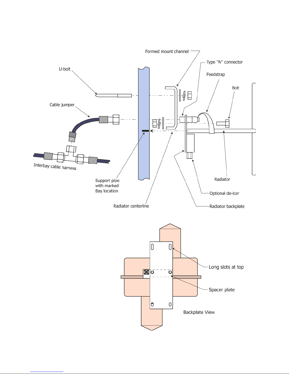
Figure 3. Installation of radiator
without radome, exploded view
Antenna Installation
Figure 4. Radome backplate
installation
5

Figure 5. Installation of radiator
with radome, exploded view
Antenna Installation
f. Sight vertically along the installation to ensure the radiators are aligned
before finally securing them to the support pipe.
g. Touch up the paint on the support pipe as necessary to protect from
corrosion.
Installing the interbay
cable harness
CAUTION
Tighten the connector nuts finger-tight only. Using pliers or other
mechanical means to tighten the connectors may damage them.
CAUTION
The minimum bend radius of RG-214 cable is 2 inches (50.8 mm).
a. Locate the end of the harness that is marked "Bay 1." Form the cable as
shown in Figure 6
and attach that end to radiator #1.
6

Figure 6. Installation of top and
bottom bays
Antenna Installation
b. The rest of the interbay cable harness should naturally fall into place. Attach
the tees on the harness to the remaining radiators, as shown in Figure 3
Figure 5
c. Repeat step a for the bottommost connection.
The design of the antenna requires that the interbay feedline be about 50%
longer than the bay-to-bay spacing. To protect the slack cable from wind and
vibration damage, it must be wrapped and secured to the support pipe.
. For antennas with radomes, use the cable jumpers as shown.
or
CAUTION
To ensure proper antenna performance, the excess feedline must be
wrapped in a particular fashion, as shown in
NOT make a continuous spiral wrap around the pipe, as shown on the
left. Doing so will ruin the VSWR of the antenna.
d. Wrap and secure the interbay feedline cable as follows (Figure 7):
Figure 7 on page 8. DO
CAUTION
Do not put too much tension on the feedline; just make it snug.
(1) Between each pair of antenna bays, loosen the connectors at both ends
just enough to allow the cable to swivel as it is wrapped. This will
prevent kinking.
(2) Grasp the feedline in the middle and pull it gently out like a bowstring.
(3) Then wrap the middle around the pipe, resulting in the “two-way spiral”
shown in Figure 7
(4) Fasten the feedline to the pipe with plastic ties or electrical tape. Do not
use metal ties, which can cut the line.
(5) Retighten the connectors at both ends.
(6) Repeat for each interbay section.
.
7

Figure 7. Wrapping and securing
the interbay cables
Antenna Installation
CAUTION
If splicing tape is not applied correctly, water can get into the coax connections and affect the performance and reliability of your antenna.
e. Apply splicing tape as follows (Figure 8 on page 9):
(1) Make sure the fittings and coax are clean and dry.
(2) Apply Scotch 130C Linerless Rubber Splicing Tape with the tacky side
up.
(3) Stretch tape and apply half-lapped to form a smooth, void-free splice.
Wrap tightly in and around the area where the connection is made.
Make sure the joint is fully covered, but do not seal up against the
bulkhead plate.
(4) Inspect the connection carefully, ensuring that the joint is fully sealed.
If more splicing tape is needed, simply add it to the existing wrap. It
adheres well to itself.
f. Stretch tape and apply half-lapped to form a smooth, void-free splice. Wrap
tightly in and around the area where the connection is made. Make sure the
joint is fully covered, but do not seal up against the bulkhead plate.
g. Inspect the connection carefully, ensuring that the joint is fully sealed. If
more splicing tape is needed, simply add it to the existing wrap. It adheres
well to itself.
8
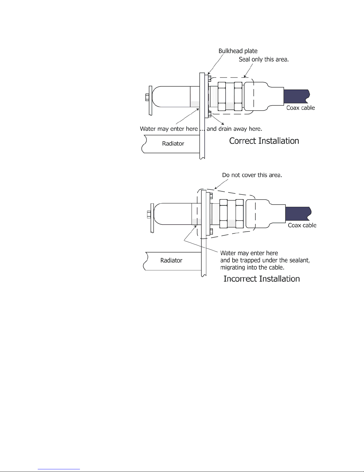
Figure 8. Proper and improper
application of splicing tape
Antenna Installation
CAUTION
To prevent damage, secure all coax to minimize wind-induced motion
and chafing.
h. Tie all coax to the mounting pipe to prevent it from damage.
9


Installing the De-icer System (if applicable)
3 Installing the De-icer System (if applicable)
Precautions
WARNING
Installation should be performed only by personnel
experienced in RF systems, qualified in electrical work, and familiar
with this equipment.
De-icer system
description
WARNING
Don't expose personnel to the medical hazards of intense radio frequency (RF) radiation. Whenever working on the tower in the area of
the antenna, turn off all transmitters and lock them out so that they can
not be turned on accidentally.
-
CAUTION
All parts of the de-icer system within approximately 20 feet (6 meters) of
any radiator must be shielded from RF energy, and the entire outdoor
portion of the system must be made waterproof.
CAUTION
An improperly installed de-icer can overheat and damage your antenna.
The de-icer system consists of the heating elements in the bays, their branch
cables, and the main harness. The main harness consists of a bay junction box
for each antenna bay, interbay cables, and a "pigtail" of wires about 10 feet (3
meters) long which you will connect to the tower junction box you are to pro
vide. The following will help in installation:
• System electrical schematic: Figure 9 on page 12.
• Electrical specifications: Table 4 on page 13.
• Bay junction box: Figure 10 on page 14.
• Thermostat readings: Table 5 on page 15.
-
Dual-setting thermostat
Electric power
Your system may also include specially-ordered items, such as a groundmounted main control box, a power cable extending up the tower, or a towermounted dual-setting thermostat.
CAUTION
Remember that conditions may be favorable for icing on the tower, even
if they are not on the ground.
Shively Labs deicers are designed to prevent ice from forming on antenna elements and are not designed to melt ice that has already formed. For this reason, Shively Labs recommends that the system be installed with a towermounted dual-setting thermostat assembly (Shively Labs Model 55522-G502)
and de-icer control box (Shively Labs Model 94068) that ensure the deicers
are operated in the temperature range ice is most likely to form.
The de-icer system requires 220 VAC, 50 - 60 Hz., single-phase. Table 4 shows
approximate heater leg resistances and current draw, respectively.
11

Figure 9. De-Icer electrical
schematic diagram
NOTE
Customer-supplied items
are shown in broken lines.
Installing the De-icer System (if applicable)
NOTE
A liquid-tight conduit connector (3/8" conduit size
by 1/2" hub size) for the
harness entry to the
tower junction box, is
packed loose with the deicer harness.
NOTE
Shively recommends the
use of shielded braided
polyethylene-covered wire
or rubber-sheathed flexible metal conduit or rigid
conduit and weather-tight
fittings at all junctions.
12

Installing the De-icer System (if applicable)
Table 4. De-Icer specifications
De-icer installation
Installing the de-icer
harness
Heater Leg
Resistance,
1-Bay 203 0.6
2-Bay 101 1.2
3-Bay 68 1.8
4-Bay 51 2.4
5-Bay 41 3.0
6-Bay 34 3.6
7-Bay 29 4.1
8-Bay, single circuit 25 4.7
10-Bay, single circuit 20 5.9
12-Bay, single circuit 17 7.1
14-Bay, single circuit 14 8.3
16-Bay, single circuit 13 9.5
a. Install the main de-icer harness with its bay junction boxes as shown in
Figure 9
bay’s de-icer pigtail to the main harness in that bay’s junction box as shown.
on page 12 and Figure 10 on page 14. Connect the leads from each
Heater Leg
(T1 or T2)
Current Draw,
amps
CAUTION
Shively Labs's de-icer
control box, Model 94068,
is designed for interior
installation only.
CAUTION
It is important to ground both the tower junction box and the control
box, as shown in the schematic diagrams.
b. Furnish a tower junction box as shown schematically in 9 to connect the
antenna’s de-icer harness to the main power.
c. Using tie-wraps, secure the entire length of the de-icer harness to the RF
feedline at abo u t 2 4 " (60 cm ) i n tervals . R u n the ten- f o o t de-icer pigtail along
a feedline mount to the tower junction box and secure it to the mount and
the tower.
13

Figure 10. Bay junction box
installation
NOTE
Wire nuts, cover with
screws, and gaskets, and
tie-wraps are provided
with the de-icer cable
harness.
Installing the De-icer System (if applicable)
Installing the thermostat
(if applicable)
If you are using a thermostat, you may locate and mount it at your discretion.
We recommend mounting it as close as practical to the antenna.
CAUTION
When testing the thermostat, be sure to have one or both thermostat
leads disconnected before taking resistance readings. Otherwise, read
ings may be affected by other components.
a. Before you connect the thermostat, measure the resistance across the
thermostat circuit and from it to ground to ensure that there are no shortcircuits. Thermostat readings should be as shown in Table 5
b. Mount the thermostat near the antenna and connect the thermostat leads to
points S1 and S2 in the control box as shown in the schematic diagram,
Figure 9
on page 12.
14
on page 15.
-

Installing the De-icer System (if applicable)
Table 5. Thermostat readings
Reading
Location
Leg-to-
Ambient
Temperature
Any Defective thermo-
Ground
Leg-to-Leg Above about 38°
F(3.3° C)
Between about 10°
and about 38° F (-
6.7° to 3.3° C)
Below about 10° F
(-6.7° C)
Resistance =
0 ohms
(short circuit)
stat or shorted
leads
Defective thermo-
stat or shorted
leads
OK Defective thermo-
Defective thermo-
stat or shorted
leads
Resistance =
infinite ohms
(open circuit)
OK
OK
stat or broken leads
OK
15


Startup and Operation
4 Startup and Operation
Precautions
The antenna
System sweep
(recommended)
Checkout
CAUTION
A high voltage standing wave ratio (VSWR) may indicate damaged transmission line or incorrectly assembled components. This condition will
cause serious damage to your equipment when full power is applied.
Shively Labs strongly recommends that you perform a system sweep of your
transmission line and antenna while you have the installation crew on site.
Should any problems arise later with your antenna, it will be extremely helpful
to know what the system’s characteristics were when it was new. We recom
mend you perform a system sweep after installation.
Many riggers can sweep your system after installation or recommend a contractor to perform it. Alternatively, Shively Labs makes available instructions
for system sweep on our Web site, www.shively.com.
Before beginning checkout of the antenna system, be sure the following items
have been done:
• The antenna system has been installed in accordance with this
manual and the installation drawing.
• The de-icer system, if purchased, has been checked out in accordance with Chapter 3.
• All radiators are operating and VSWR is low.
• System sweep data, if desired, have been recorded.
-
Operation
The de-icer system
Check the system out as follows:
a. Bring up RF power slowly and observe transmitter readings, stability, and
general operation.
b. Run at about half power for at least an hour, reading forward and reflected
power, stability, etc.
c. If the system is stable and seems to be operating properly, bring it up to full
power. Take initial and periodic readings.
d. Performance readings should not change, and there should be no evidence
of heating in the antenna system.
CAUTION
Don't exceed the rated power capacity of the antenna.
To obtain the best performance and dependability, read and follow the maintenance and troubleshooting recommendations in Chapter 5 of this manual.
CAUTION
Don't leave the de-icer on for extended periods when the weather is
above 60° F (16° C); doing so may shorten the life of the heater ele
ment(s).
-
17

Startup and Operation
There is a generous margin of safety built into the de-icer system, and operation for prolonged periods below 60° F (16° C) will not harm the system. If
icing conditions are expected, the heaters should be turned on in advance as a
preventive measure. It is much easier to prevent ice formation than to remove
a heavy coating.
Shively Labs de-icer control
system
If you have the Shively Labs de-icer control box and dual-setting thermostat,
you have the choice of manual or automatic operation. There are three switch
settings: AUTOMATIC, OFF, and MANUAL.
• When the switch is set to AUTOMATIC, the thermostat turns the
heaters on and off according to the temperature.
• When the switch is set to OFF, the thermostat is overridden and the
heaters will stay off no matter what the temperature.
• When the switch is set to MANUAL, the thermostat is overridden
and the heaters will stay on no matter what the temperature.
18

Maintenance and Troubleshooting
5 Maintenance and Troubleshooting
Precautions
WARNING
Maintenance should be
performed only by personnel experienced in RF
systems and familiar with
this equipment.
Maintenance log
Physical inspection
Important
Give your antenna a full
inspection at least once
per year!
WARNING
Don't expose personnel to the medical hazards of intense radio frequency (RF) radiation. Whenever working on the tower in the area of
the antenna, turn off all transmitters and lock them out so that they can
not be turned on accidentally.
Shively recommends that you keep a maintenance log, recording important
performance parameters such as VSWR readings, de-icer current draw, main
tenance done on the tower and the antenna, and severe weather events. This
information can be valuable for identifying and solving problems.
maintenance log on page 22 shows a suggested log form.
The antenna system should operate for years if properly installed and maintained. Shively Labs recommends that as a minimum, the antenna should be
physically inspected
In addition, inspect the antenna after severe weather events, and after climbers have been on the tower working on equipment above the antenna.
In addition to checking the general condition of the antenna and coax:
• Replace dented, broken or bent components.
• Inspect radomes for cracks and plugged drain holes.
at least once a year
.
Sample
-
-
Paint
Radome removal and
reinstallation
• Re-tighten all hardware, hose clamps, and U-bolts to installation
specifications.
• Inspect hose clamps and U-bolts carefully for signs of wear or
fatigue caused by vibration or tower movement.
The radiators should never be painted (a coating of paint affects VSWR), and
they need no surface protection, since they are made of copper and brass.
This includes Teflon or other "ice-prevention" coatings.
It is not necessary to paint the feedline, although no harm will result from
doing so.
If it becomes necessary to remove a standard radome to gain access to the
radiator, first remove the radiator as described above and bring it to the
ground. If the antenna is to be operated without that radiator, be sure to
observe all precautions.
On the ground, merely remove the ten bolts that secure the radome halves
together, and the four additional 3/8” bolts securing the formed channel to the
radome backplate, and lift the radome away from the radiator. Reinstall the
radome and the radiator in the reverse order of removal. Re-seal the radome,
using Dow Corning 732 Multipurpose RTV or equivalent.
19

Maintenance and Troubleshooting
Return policy
Troubleshooting
Internal arcing
Broad spectrum RF noise
High VSWR at startup or
during operation
When returning any material to the factory, be sure to call your salesman and
obtain an returned material authorization (RMA) number first. Use this num
ber in all correspondence. This number helps us to track your returned item. It
will expedite repair or replacement and prevent loss of your material.
Cantact Shively Labs if necessary to help find the cause of your problem. Outside of 8:00 AM to 5:00 PM Eastern Time, call (207) 329-5118.
Internal arcing is caused by physical damage to transmission line, feedline, or
radiators. Damage may have been caused by ice, lightning, tower work, or
many other factors. Replace damaged components.
Any metal part in poor contact with the tower will constitute a non-linear junction and cast a broad-spectrum signal. This includes antennas, transmission
line, mounts, ladders, and other electrical components. Check your antenna
mounts and other tower components to be sure that the tower paint was
scraped away during installation and that all mounting hardware is tight.
High VSWR (Voltage Standing Wave Ratio) is caused by any factor which
changes the impedance match between the transmitter and the antenna sys
tem. Possible causes include:
• Wrong antenna for the application and frequency. Occasionally
in correct frequency i nformati o n is provi ded to Shively or an a ntenna
designed for another application is used.
• Defective cable connector in the cable harness.
-
-
Change in coverage
• Incorrect assembly of the antenna (for example, an upside-down
radiator; radiators out of sequence). The assembly must be exactly
as shown in the installation drawing.
• Damaged radiator feed strap(s). The feed strap is the metal strip
that extends back from the end seal. The length, angle, and
straightness of the feed strap are critical to the radiator's perfor
mance.
• Components of other services in the RF field (later installations or
broken components).
• Physical damage to the transmission line, feedline, or radiators.
This may be from ice, lightning, tower work, or any other source.
(Check with the tower owner to see whether anyone has been
working on the tower.)
• Paint applied to the radiators, for example during a recent tower
painting.
• De-icer failure may have allowed ice buildup or melted the solder
from the domes, spacers, and bushings at the ends of the vertical
arms.
Changes in broadcast coverage may be caused by the same factors that produce VSWR changes. If coverage seems to have changed, look for VSWR
changes and use
troubleshooting.
High VSWR at startup or during operation on page 20 for
-
20

Maintenance and Troubleshooting
It is important to recognize, however, that apparent changes in coverage may
be due to subjective factors or faults of the receiving equipment. Before doing
more than checking the VSWR, be sure that an actual coverage change has
occurred.
21

Sample maintenance
log
Maintenance and Troubleshooting
DATE DE-ICER CURRENT
(or resistance)
BLACK
(b-neut)
NEUT
(red-bl)
(r-neut)
RED
VSWR OBSERVATIONS
Visual Inspection of Antenna, Obstruction Lighting; Hard
ware Checked; Tower Repairs Accomplished; etc.
-
22
 Loading...