


FM Broadband Multistation
Broadcast Antenna
Model 6017
Instruction Manual
Installation, Operation, &
Maintenance

Congratulations!
Thank you for purchasing one of the finest FM broadcast antennas on
the market today. The Shively Labs 6017 antenna is widely recognized
as the top-of-the-line in its class for its superior performance and dura
bility.
Your purchase is backed by the best technical support in the industry.
Shively is a leading manufacturer in the broadcast industry, providing
an extensive range of antennas, transmission line and components.
Our technical staff has a wealth of experience in the broadcast indus
try and is standing by to serve you in any way.
This manual is intended to give you a good basic understanding of your
antenna: its proper and safe installation, startup, and operation, and
troubleshooting and maintenance information to keep it working satis
factorily for years to come.
Please have everyone involved with the
antenna read this manual carefully, and keep it handy for future refer
-
-
-
ence.
Meanwhile, please feel free to contact your sales representative at
Shively Labs at any time if you need information or help. Call or write:
-
Publication No. IM017 (100201)
2

IMPORTANT
Please read this manual in its entirety before beginning
installation of your antenna!
Failure to follow the installation and operation
instructions in this manual could lead to failure of your
equipment and might even void your warranty!


Table of Contents
Chapter 1 Preparing for Installation..................................................1
Receiving ............................................................................................. 1
Unpacking............................................................................................ 1
Check the System ................................................................................. 2
Chapter 2 Installing the Mounts .................................................. ...... 3
Before Beginning Mount Installation :......................................................3
Mark Mount Locations on the Mounting Pole ...........................................3
Installing the Radiator Mounts on the Pole.............................................. 3
Installing the 4-Way Power Divider Mounts on the Pole ........................... 4
Installing the Main Power Divider Mounts
(if applicable) .................................................................... 6
Chapter 3 Installing the Radiators and Power Dividers.....................8
Before Beginning Radiator and Power Divider Installation: ....................... 8
Installing Radiators ............................................................................... 8
Installing Power Dividers ....................................................................... 9
Chapter 4 Installing the Coaxial Feed System.................................10
Before Beginning Feed System Installation : .......................... ................ 10
Installing the Power-Divider-to-Radiator Cables..................................... 11
Installing the Main Power Divider (if applicable) .................................... 12
Installing the Main Feed Cables............................................................ 12
Chapter 5 Pressurization and Startup..............................................14
Before Beginning Pressurization:............................ .... .. .. .... .. ... .. .... .. .. .. . 14
Pressurization Procedure ..................................................................... 14
Step 1. Leak Testing....................................................................... 14
Step 2. Purging the System............................................................. 16
Step 3. Leaving the System Pressurized ........................................... 17
Before Beginning Intial Characterization: .............................................. 17
Initial Characterization (recommended) ................................................ 18
Step 1. Transmission Line VSWR Reading ........ ................................ 18
Step 2. Transmission Line TDR Reading........................................... 19
Step 3. System VSWR Reading...................................... .................. 19
Step 4. Checking Radiator Function ................................................. 19
Checkout............................................................................................ 19
Chapter 6 Operation.........................................................................21
Precautions ........................................................................................ 21
The Antenna.......... .. .. ... .... .. .. .. .. .. ..... .. .. .. .. .. .... .. ... .. .. .. .... .. .. .. ... .... .. .. .. .. . 21
Chapter 7 Troubleshooting .............................................................. 22
Precautions ........................................................................................ 22
Internal Arcing....................................................................... ............. 22
Broad Spectrum RF Noise.................................................................... 23
High VSWR at Startup or during Operation............................................ 23
Erratic VSWR...................................................................................... 24
Change in Coverage............................................................................ 24
Pressure Loss or Excessive Gas Usage .................................................. 24
i

Table of Contents
(continued)
Chapter 8 Maintenance ........................................... .........................26
Precautions.........................................................................................26
Maintenance Log............................................ ..................................... 26
Physical Inspection.................... ..........................................................26
Paint..................................................................................................27
Troubleshooting.................................................................................. 27
Return Policy ......................................................................................27
Sample Maintenance Log.............................. .. .. ... .... .. .. .. .. .... ... .. .. .. .... .. . 2 8
List of Illustrations
List of Tables
Figure 1 Typical Mount Installation on Pole, top view.........................3
Figure 2 4-Way Power Divider Installation, top and side views............5
Figure 3 Main Power Divider Mount Styles.........................................6
Figure 4 Radiator Installation, top view.............................................9
Figure 5 Feedline Flange Detail ......................................................10
Figure 6 Flange Bolt Tightening Sequences..................................... 12
Figure 7 Pressurized Gas Schematic..... ........................................... 15
Table 1 Minimum Bending Radii, Semiflex Coax..............................10
Table 2 Torque Specifications, Flange Bolts....................................11
Table 3 Volume of Coax per 1000 Feet of Length...........................17
Table 4 Troubleshooting Internal Arcing ....................................... 22
Table 5 Troubleshooting High VSWR ............................................23
Table 6 Troubleshooting Pressure Loss or Excessive Gas Usage.......24
ii

Preparing for Installation
1 Preparing for Installation
Receiving
Unpacking
As soon as you receive your antenna, BEFORE signing for the shipment:
a. Check to be sure all the material has arrived.
NOTE
The box number and the total number of boxes are marked on
each box; for example, “Box 2 of 5” means “box number 2 of a
total of five boxes.”
b. Check for evident damage to any of the boxes.
c. If any boxes are missing, or if any are obviously damaged, describe
the problem in a WRITTEN note on the shipping papers BEFORE
signing them. Then call Shively right away, and we’ll do everything
we can to correct the situation.
Important!
Never store the antenna system outdoors, boxed or otherwise.
Take pains to keep the antenna components dry. You will need to
purge moisture from the interior of the antenna components
before applying transmitter power, and purging will be much more
time-consuming if the components get wet.
a. Find Box 1; it is marked “Open This Box First.” It contains the trans-
former and two copies of the installation drawing. The parts list on
one sheet of the installation drawing shows what box each item is in.
b. Then open the boxes and examine for shipping damages. File any
necessary claims with the carrier immediately.
c. If all the boxes are present and in good condition but material seems
to be missing, please contact Shively Labs immediately, using the
telephone or Fax number on the inside cover of this manual. For the
best service, have our shop order number (S/O) handy; it's in the
block at the bottom right corner of the installation drawing.
d. Along with your antenna you will get a spare parts kit. Place this in a
safe place until it is needed.
CAUTION
All contact surfaces and openings to the interior of the components are protected from contamination and from physical damage by caps and plastic bags. Do not remove this protection until
ready to connect the components.
1

Preparing for Installation
Check the System
Remember!
It is YOUR responsibility to ensure that your installation meets all
applicable codes and the centerline-of-radiation requirements of
your FCC construction permit.
Shively's factory designer has planned the installation of the antenna
based upon information provided by you. If this information contained
errors, the parts and mounting hardware will have been designed
incorrectly and will cause expensive delays in installation.
Therefore,
we recommend that you recheck the installation parameters during this
planning stage.
Check all the parts to be sure that they will fit the tower and each
other. Study the installation drawings carefully to confirm that the infor
mation used in designing the antenna and mounts was, in fact, accurate.
Have a reliable tower person, familiar with antennas and coaxial line,
inspect the tower and review the installation drawings before the full
rigging crew arrives.
If design problems are found, contact Shively Labs immediately. Pay
particular attention to:
• Frequency of the antenna.
-
• Fit of the mounts to the tower members.
• Freedom from interference by gussets, leg flanges, guys and their
attachment points, tower face members, obstruction lights, and
other components.
• Compatibility of transmission line and antenna input terminals.
• Location of the transmission line run relative to the antenna input
terminal.
• Use of non-metallic guy sections on the tower in the region to be
occupied by the FM antenna. Ensure that there are no metal guys
within ten feet (three meters) of any radiator.
• Availability of proper electrical service for deicers, if applicable.
• The adequacy of the tower structure and guys to carry the windload
placed upon them by the antenna.
You gave Shively this information at the time of purchase, but a last
check at this time can catch an error, which will be easier to correct
before installation begins.
2

Installing the Mounts
2 Installing the Mounts
Before Beginning
Mount Installation:
Mark Mount
Locations on the
Mounting Pole
Installing the
Radiator Mounts on
the Pole
CAUTION
Before you begin, study the installation drawing carefully. The
illustrations in this manual show typical details, but antennas vary
due to pattern requirements and tower designs, so you must go
by the installation drawing for the actual configuration of your
antenna.
a. Starting at the top of the antenna, use a steel measuring tape to find
the location of each mount in accordance with the installation draw
ing. Mark the mount locations on the pole.
b. Also mark the location on the pole of any accessory mounts, such as
for the power dividers or special coax line sections, to make sure
they will fit as planned.
c. If any problems appear during this process, please call Shively Labs
and discuss them with the installation designer.
-
(not to scale)
Figure 1. Typical Mount Installation on Pole, top view
3

Installing the Mounts
Figure 1 is a top view showing how the radiator mount pieces fit
together. Assemble and install the radiator mounts according to Figure
1, your installation drawing, and the following guidelines:
a. Find the marked locations on the mounting pole where the radiator
mounts will be located.
b. To ensure good electrical contact between the mounts and the sup-
port pole, scrape the pole paint away at the mount locations.
c. Install the mounts as shown in Figure 1 and your installation draw-
ing.
d. When all mounts are in place, sight along them vertically to make
sure they are aligned before tightening them.
e. Repaint the pole where you remo ved the paint in step b.
Installing the 4- Way
Power Divider
Mounts on the Pole
Assemble and install the 4-way power divider mounts according to Fig-
ure 2 on page 5, your installation drawing, and the following guide-
lines:
a. Find the marked locations on the mounting pole where the power
divider mounts will be located.
b. Referring to the installation drawing, mark the locations of the power
divider mounts (generally there will be either two or four mounts per
power divider).
CAUTION
If you don't get good electrical contact between the mounts and
the pole, the antenna may not perform as designed, and may pro
duce stray signals that will interfere with other services on the
tower.
c. To ensure good electrical contact between the mounts and the sup-
port pole, scrape the pole paint away at the power divider mount
locations.
d. Use band clamps to attach the power divider mounts loosely to the
pole.
e. When all mounts are in place, sight along them vertically to make
sure they are aligned before tightening them.
-
f. Repaint the pole where you removed the paint in step c.
4

Installing the Mounts
(not to scale)
Figure 2. 4-Way Power Divider Installation, top and side views
5

Installing the Mounts
Installing the Main
Power Divider
Mounts
(if applicable)
If your antenna has more than one level, a main power divider will distribute the signal among the 4-way power dividers at each antenna
level. Assemble and install the main power divider mounts according to
Figure 3, your installation drawing, and the following guidelines:
(not to scale)
Figure 3. Main Power Divider Mount Styles
6

Installing the Mounts
a. Find the marked location on the mounting pole where the power
divider mounts will be located.
b. Referring to the installation drawing, mark the locations of the power
divider mounts (generally there will be two mounts).
CAUTION
If you don't get good electrical contact between the mounts and
the pole, the antenna may not perform as designed, and may pro
duce stray signals that will interfere with other services on the
tower.
c. To ensure good electrical contact between the mounts and the sup-
port pole, scrape the pole paint away at the power divider mount
locations.
d. Use band clamps to attach the power divider mounts loosely to the
pole.
e. Repaint the pole where you removed the paint in step c.
-
7

Installing the Radiators and Power Dividers
3 Installing the Radiators and Power Dividers
Before Beginning
Radiator and Power
Divider Installation:
Installing Radiators
CAUTION
All electrical contact surfaces and openings to the interior of the
components are protected from contamination and from physical
damage by plastic protectors. Do not remove the protectors until
ready to connect the components.
CAUTION
The interiors of the components must be kept dry during installation. Avoid assembly during wet weather.
NOTE
Keep the plastic protectors in case you ever need to return components for repair.
CAUTION
Do not use silicone grease on an O-ring, as this will soften the silicone O-ring. Use only a light lubricating coat of petroleum jelly
(provided); too much may hamper electrical contact and contami
nate the interior of the system.
Be sure the O-ring is properly seated in its groove and not
pinched between the flange contact surfaces.
Attach the radiators to their mounts according to Figure 4 on page 9
and your installation drawing.
-
a. Fit the holes in the radiator backpalte over the studs on the mount.
b. Attach the radiator to the mount, using the 3/8” hardware provided.
8

Installing the Radiators and Power Dividers
Installing Power
Dividers
(not to scale)
Figure 4. Radiator Installation, top view
Assemble and install the power dividers and their mounts according to
your installation drawing and the following guidelines:
a. Check the mount locations against your installation drawing.
b. Attach the power dividers to the mounts as shown in Figure 2 on
page 5.
c. Double-check the tightness of all components.
9
4 Installing the Coaxial Feed System
Before Beginning
Feed System
Installation:
Installing the Coaxial Feed System
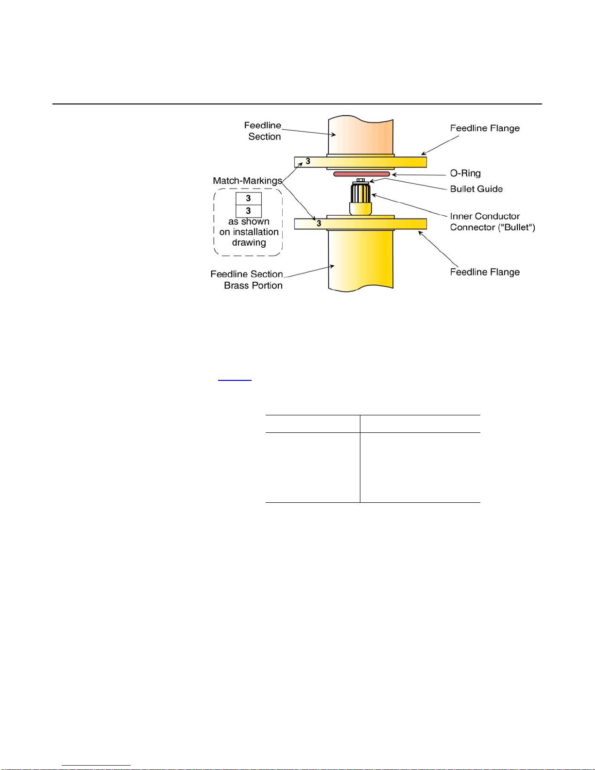
Figure 5. Feedline Flange Detail
CAUTION
Semiflex cable has a minimum bending radius, specified by the
manufacturer. Bending it too sharply will damage the cable. See
Table 1 for the various sizes.
Table 1. Minimum Bending Radii, Semiflex Coax
Cable Size Radius
1/2” 5” (127 mm)
5/8” 5” (127 mm)
7/8” 10” (254 mm)
1-5/8” 20” (510 mm)
CAUTION
Stressing a coax connection after assembly can detune the system. Therefore, never make a connection and then bend or twist
the cable.
Likewise, do not use the connector and flange to force the coax
into shape. Form the coax to the desired shape before attaching it
and align the connection properly, then make the connection.
10

Installing the Coaxial Feed System
CAUTION
Do not use silicone grease on the O-rings, as this tends to dissolve the silicone O-ring. Use only a light lubricating coat of petroleum jelly; too much may hamper electrical contact and
contaminate the interior of the system.
Be very careful that each O-ring is seated in its groove and not
pinched between flange contact surfaces, as this will cause a leak
in the system and will be expensive to find and repair.
NOTE
Keep the hardware securing the plastic protectors. It will be used
for the final connections.
Installing the
Power-Divider-toRadiator Cables
The semiflex cables have been pre-formed at the factory and marked
for their respective locations. Use the markings to determine which
cables go where. Install the power-divider-to-radiator flex coaxial
cables as shown on the installation drawing. Follow these guidelines:
CAUTION
Be very careful to connect each power divider port to the correct
radiator.
CAUTION
The specific lengths of your flex cables are required to maintain
proper system phasing. Often cables will be longer than needed
merely to reach the antenna inputs. This is normal and necessary.
a. Remove the plastic protector from the coax flange. Don’t lose the
hardware or the O-ring.
b. Lubricate the O-ring lightly and insert it into the groove in the coax
flange.
CAUTION
Be sure each component’s inner conductor fits cleanly over the
mating component’s inner conductor connector. If any of the fin
gers of the connector are forced outside the inner conductor (a
"split bullet"), this will cause arcing and damage to the antenna.
-
c. Use the hardware from the protective covers to attach the compo-
nents. Table 2 shows torque specifications for the v arious siz e flange
bolts. Figure 6 shows the flange bolt tightening sequence for each
coax size.
Table 2. Torque Specifications, Flange Bolts
Line Size Bolt Size Torque
1/2” 1/4-20 7 ft-lb 9 N-m
5/8” 1/4-20 7 ft-lb 9 N-m
7/8" 1/4-20 7 ft-lb 9 N-m
1-5/8" 5/16-18 12 ft-lb 16 N-m
11

Installing the Coaxial Feed System
Figure 6. Flange Bolt Tightening Sequences
d. After all RF components (ie: power dividers, radiators, rigid coax)
have been connected to each other, tighten the mounting bolts
securing the RF feed system to the pole.
Installing the Main
Power Divider (if
applicable)
Installing the Main
Feed Cables
If your antenna has more than one level, a main power divider will
feed it, with a cable to the four-way power divider at each level. Install
the power divider in accordance with
installation drawing.
a. Secure the power divider to the mount saddles using the band
clamps provided (generally, two clamps on a 6"-long saddle and four
clamps on a 12"-long saddle).
b. Connect the flex coax from the main power divider to the four-way
power dividers at the antenna levels.
Figure 3 on page 6 and your
CAUTION
To prevent damage to power dividers, position the hose clamp
screw housings over the saddles, not against the power dividers.
c. As each feedline section is lifted into place, remove the plastic bags
and protective covers from the flanges and install an O-ring, lubricat
ing it with a light coat of petroleum jelly (provided with the antenna).
d. Secure each feedline section to its mount before installing the next
section.
A main feed cable brings power from the main power divider to the
four-way power divider at each level of the antenna.
CAUTION
Components are usually interchangeable and are therefore not
normally match-marked in any way. Assemble any bay to any feed
cable, with any mount, etc. If any matching is necessary with your
system, it will be indicated on the installation drawing.
-
CAUTION
Be very careful to connect each power divider port to the correct
radiator.
Install these cables in the same manner as the power-divider-to-radiator cables. Their mounts are similar to the four-way power divider
mounts, but slightly larger to accommodate the corrugated cable outer
conductor.
12

Pressurization and Startup
5 Pressurization and Startup
Before Beginning
Pressurization:
Important
Shively Labs will not accept responsibility for antenna failure after
operation without proper purging or positive pressure of dry air or
dry nitrogen.
CAUTION
When pressurizing the system, never use a "garage" air compressor, as it will not clean the air and will blow both moisture and
contaminants such as oil and graphite into the coaxial system.
Be sure to use a good quality pressure gauge which will read
accurately in the 10 - 20 psig range; don't depend on the cylinder
gauge, which will not be accurate at a low pressure.
Do not over-pressurize the system; it takes time for the entire system to fill with the new pressure and the pressure gauge to stabilize.
CAUTION
If all moisture is not removed from the interior of the system, it
will condense when the weather cools. The condensed moisture
(water) will cause arcing and permanent physical destruction of
the coaxial system, including the transmitter outp ut network.
CAUTION
You must blow dry gas
pressure. The gas
volume
through
accomplishes the purge.
the system, not just maintain a
Pressurization
Procedure
Step 1. Leak Testing
CAUTION
Never operate the antenna system without proper purging and
constant positive dry gas pressure.
CAUTION
Although initial characterization is at your discretion, we strongly
recommend it as the best way to identify both initial problems and
possible future system damage.
After the antenna is installed and all lines are connected, it is necessary to check the system for leaks, purge with dry gas to remove all
moisture, and leave the system pressurized with dry gas to av oid f uture
infiltration of moisture. These steps must be taken before RF power is
applied to the system.
a. Connect a source of dry gas (cylinder nitrogen or air from a compres-
sor-dehydrator) to the system as shown in Figure 7 on page 15.
b. Be sure to include a good quality gauge which reads accurately in the
5 - 20 psig (35 - 135 kPa) range; don't depend on the cylinder
gauge, which will not be accurate enough in this pressure range.
14

Pressurization and Startup
Pressure Correction:
where PC = corrected
final pressure, psig
P
= final pressure as
R
read, psig
T
= beginning temper-
1
ature, degrees F.
= final temperature,
T
2
degrees F.
Figure 7. Pressurized Gas Schematic
c. Pressurize the system to eight (8) psig, then close the shutoff valve.
Give the system one half hour to stabilize, then record the pressure
and the temperature.
d. W ait twenty -f our hours, then read the pressure and the temperature
again and use the formula in the sidebar to obtain a corrected pres
sure for comparison.
e. If the system loses pressure at an unacceptably high rate, re-pres-
surize it, leaving the gas supply on. A rule of thumb is that the final
pressure should not be less than half the initial pressure after
twenty-four hours.
15
-

Pressurization and Startup
f. Find the leak(s), using a leak detector or soap bubbles. (The most
common cause of leakage is an O-ring pinched in a flange.)
g. Correct any leaks that are found. Then repeat the leak test until the
results are satisfactory.
Step 2. Purging the
System
When the system is new, and any time that it has been opened, it must
be purged with dry gas before operation to eliminate moisture.
The dry gas used may be dry cylinder nitrogen or air from a compressor-dehydrator. Shively Labs suggests three volume changes of dry gas
for an "average" system.
There is a pressure relief valve at the top of each four-way power
divider. This valve is set to open at about 10 psig. So, to purge the sys
tem, it is not necessary to send a worker to the top of the antenna to
open a valve or loosen a flange. Simply raise the internal pressure
enough to open the relief valve. When the purge is complete, lower the
pressure and the valve will close.
Purge your system as follows:
a. Determine how wet the system is. If a system of rigid line carefully
protected from weather and assembled in dry weather is average, a
system exposed to moisture during storage or installation will be rel
atively wet. New semi-flex transmission line, delivered pressurized
with dry gas, will be relatively dry; used semi-flex will be extremely
wet.
Important
Never apply transmitter power while the antenna is under vacuum.
-
-
b. If you have any liquid w ater in your tr ansformer or your tr ansmission
line, use a vacuum pump to dry the transmission line and trans
former. Apply as much vacuum as you can to the system and hold
the vacuum for 8 hours. This should remove an y liquid w ater. [A vac
uum pump can be rented or borrowed from a refrigeration contractor.]
c. Determine the volume of dry gas to use for the purge.
d. Table 3 shows approximate volumes inside various coax sizes. Add
the length of the antenna to the length of the transmission line to
determine the overall length of the system. You may ignore the vol
-
ume inside the radiators.
16
-

Pressurization and Startup
Table 3. Volume of Coax per 1000 Feet of Length
Coax Size Volume
1/2" 2 cu. ft. (0.06 m3)
5/8" 3 cu. ft. (0.08 m3)
7/8" 4 cu. ft. (0.11 m3)
1-5/8" 13 cu ft. (0.37 m3)
NOTE
A standard nitrogen cylinder (9 inch diameter by 55 inches tall)
contains about 200 cubic feet (2.6 m
els 1235 and 2577 compressor-dehydrators will provide about 12
cubic feet (0.34 m
3
m
) per hour.
e. Connect a source of dry gas (cylinder nitrogen or air from a compres-
sor-dehydrator) to the system as shown in Figure 7.
f. Raise the gas pressure to 12 or 13 psig (83 - 90 kPa).
3
) per hour; the Model 1234 about 78 cu ft (2.2
3
) of gas. Shively Labs Mod-
Step 3. Leaving the
System Pressurized
Before Beginning
Intial
Characterization:
g. If the relief valve has opened, the nitrogen cylinder will slowly drain
or the compressor-dehydrator will not shut down.
Remember
It is critical to blow dry gas
merely maintain a pressure; the gas volume accomplishes the
purge.
After completion of the purge, reduce the supply pressure to about 5 to
7 psig, allowing the pressure relief valve to close and seal the system.
After the pressure has stabilized, keep careful note of cylinder pressure or compressor-dehydrator running time, to be sure that no large
leaks have been overlooked. This is especially important immediately
after installation or any subsequent opening and reassembly.
Although initial characterization is at your discretion, we strongly recommend it as the best way to identify both initial problems and possible future system damage.
through
the system, rather than
17

Pressurization and Startup
Important
In the days before the hazards of intense RF power were realized,
it was common practice to have a technician climb the tower and
adjust the impedance match using the transmitter as a signal
source and reading the VSWR or return power on the transmitter.
This practice MUST NOT be used, as few transmitters can be
operated at a low enough power level to av oid exposing the rigger
to an unsafe RF level. For ref erence, see 29 CFR, Section 1910.97,
the OSHA standard for exposure to non-ionizing radiation.
To test and adjust VSWR safely, use low-power test equipment,
such as a network analyzer or an impedance bridge. If you don't
have access to low-power test equipment, please call Shive ly Labs
before proceeding.
WARNING
Whenever a rigger is on the tower in the area of the antenna,
shut off the transmitter signal and lock it off so that it cannot be
turned on accidentally.
Low-power test equipment should be used to prevent excessive radiation exposure to the person doing the adjusting.
Initial
Characterization
(recommended)
Step 1. Transmission
Line VSWR Reading
CAUTION
A high transmission line VSWR may indicate damaged transmission line and is likely to cause problems in the future, including
serious damage to your equipment.
Should any problems arise later with your antenna, it will be extremely
helpful to know what the system’s characteristics were when it was
new. We recommend you perform the tests in this section after installa
tion.
The first step is to characterize the transmission line by itself
a. Briefly disconnect the transmission line from the antenna system
input. Seal the antenna system input to prevent the entry of mois
ture.
b. Terminate the coax transmission line in an instrument-quality 50-
ohm load.
c. Measure and record the voltage standing wave ratio (VSWR). File
this information with this manual for future reference.
d. The VSWR of the transmission line should be within the man ufac-
turer's specifications. If it is, proceed. If not, you should call the
manufacturer before connecting the antenna. Problems must be
worked out with the design engineer on a case-by-case basis.
-
-
18

Pressurization and Startup
Step 2. Transmission
Line TDR Reading
Step 3. System VSWR
Reading
Step 4. Checking
Radiator Function
With the transmission line still terminated in 50 ohms, make a time
domain reflectometer (TDR) plot. Label and file the plot with this man
ual.
You tested the VSWR of the transmission line alone. Now test the
VSWR of the system as a whole.
a. Remove the load and connect the transmission line to the trans-
former input, with an O-ring to seal the connection.
b. Repeat the purge process after sealing the line, in accordance with
Purging the System on page 16.
c. Measure VSWR. VSWR at this point should be below 1.2 : 1.
d. Record the reading and file it with this manual.
If VSWR is not satisfactory, check to be sure all the radiators are func-
tioning (see below). If they are, call Shively Labs to help identify the
problem.
Again using the low-power test equipment to provide a signal to the
antenna and read VSWR, have the rigger detune each radiator in turn.
The simplest way to detune a radiator is to short across the "wings" or
dipole arms, for instance with a screwdriver or wrench.
-
Checkout
Each time, a deflection in VSWR should be apparent. The deflection for
various bays should be similar, but not necessarily identical.
If the VSWR of the array does not change when a radiator is detuned,
that bay is not functioning. Check to be sure the radiator was installed
properly, including the inner conductor connector.
If you cannot find the problem, please call Shively Labs before proceeding.
Before beginning checkout of the antenna system, be sure the following items have been done:
• The antenna system has been installed in accordance with this manual and the installation drawing.
• All radiators are operating and VSWR is within specification.
• The initial characterization data have been recorded.
• The system is gas-tight and purged.
Check the system out as follows:
a. Bring up RF power slowly and observe transmitter readings, stability,
and general operation.
b. Run at about half power for at least an hour, reading forward and
reflected power, stability, etc.
19

Pressurization and Startup
c. If the system is stable and seems to be operating properly, bring it
up to full power. Take initial readings, and repeat the readings peri
-
odically.
Performance readings should not change, and there should be no evidence of heating in the antenna system.
If any problem is found, fix it now. Call Shively Labs if you need help or
advice.
20

Operation
6 Operation
Precautions
The Antenna
The broadcast industry has recently recognized the potential medical
hazards of intense radio frequency radiation. Don't expose personnel to
personal harm. For reference, see CFR 29, Section 1910.97, the OSHA
standard for exposure to non-ionizing radiation.
WARNING
Whenever a rigger is on the tower in the area of the antenna,
shut off the transmitter and lock it off so that it cannot be turned
on accidentally.
CAUTION
Never operate the antenna system without proper purging and
constant positive dry gas pressure. Shively Labs will not accept
responsibility for antenna failure after operation without proper
purging or positive pressure of dry air or dry nitrogen.
Once the antenna has been installed and tested according to this manual, simply apply the transmitter signal. Don't exceed the rated power
capacity of the antenna.
To obtain the best performance and dependability from your Shively
Labs antenna, read and follow the "maintenance" section of this man
ual.
-
21

Troubleshooting
7 Troubleshooting
Precautions
WARNING
Troubleshooting should be performed only by personnel experienced in RF systems and familiar with this equipment.
WARNING
The broadcast industry has recently recognized the potential medical hazards of intense radio frequency radiation. Don't expose
personnel to personal harm. For reference, see CFR 29, Section
1910.97, the OSHA standard for exposure to non-ionizing radia
tion. Whenever a rigger is on the tower in the area of the
antenna, shut off the transmitter and lock it off so that it cannot
be turned on accidentally.
-
CAUTION
Whenever you have the system o pen for repair, you must purge it
again as described in
begin operating the system under power until you are sure all the
moisture has been purged from it. You can do permanent damage
to the entire system, including the transmitter.
Purging the System on page 16. Never
CAUTION
VSWR does not change of its own accord. If you find you must
repeatedly readjust the transformer to correct the VSWR, find and
correct the problem quickly. Otherwise, you will almost certainly
burn up your antenna and damage your transmitter. Look for the
cause in the following table.
Internal Arcing
Look for the cause of internal arcing in Table 4.
Table 4. Troubleshooting Internal Arcing
Possible Causes: Cures:
Physical damage to transmission
line, feedline, or radiators.Dam
age may have been caused by
ice, lightning, tower work, or
many other factors.
Damage may cause arcing
directly or by allowing water
inside the system.
Missing or misaligned O-ring, if
the system has been opened re
cently.
Loss of pressurization. Locate the leak. Re-purge in accor-
22
Locate the damage. Replace dam-
-
aged components.
Purge the system after repair, in
accordance with
tem on page 16.
Locate the O-ring leak, using soap
-
solution. Replace the O-ring if
damaged.
dance with Purging the System on
page 16 and restore pressurization.
Purging the Sys-

Troubleshooting
Broad Spectrum RF
Noise
High VSWR at
Startup or during
Operation
(may interfere with other
services on the tower)
This indicates that some metal components are not in good electrical
contact with the tower. First, check your antenna mounts, then other
tower components, to be sure that the tower paint has been scraped
away and that all mounting hardware is tight.
Any metal part in poor contact with the tower will constitute a non-linear junction and cast a broad-spectrum signal. This includes antennas,
transmission line, mounts, ladders, and other electrical components.
High VSWR (Voltage Standing Wave Ratio) is caused by any factor
which changes the impedance match between the transmitter and the
antenna system.
Look for the cause in Table 5.
Table 5. Troubleshooting High VSWR
Possible Causes: Cures:
Wrong antenna for the application
and frequency. Occasionally a cus
tomer provides wrong data to Shively
or buys a used antenna designed for
another application.
Contact your sales representa-
-
tive at Shively Labs.
Split bullet in the transmission line or
in the baymount (see
page 10). A split bullet is an inner
conductor connector misaligned such
that one or more of its contact arms
is stuck outside the conductor in
stead of inside. (A missing bullet will
cause infinite VSWR.)
Mismatched assembly of the antenna. The assembly must be exactly as
shown in the installation drawing.
Radiators out of sequence (especially
on a null-filled or half-wave-spaced
system).
Components of other services have
entered the RF field (later installa
tions or broken components).
Physical damage to the cables, power dividers, or radiators. This may be
from ice, lightning, tower work, or
any other source.
Figure 5 on
-
-
Replace the inner conductor
connector. It may also be nec
essary to replace the inner conductor section if it has been
damaged.
Reassemble according to the installation drawing.
Assemble the antenna exactly
as shown in the installation
drawing and as marked.
Remove broken components.
Rearrange tower components
as necessary to correct the
VSWR problem.
Replace damaged components.
-
23

Troubleshooting
Table 5. Troubleshooting High VSWR (continued)
Possible Causes: Cures:
Erratic VSWR
Change in Coverage
Paint has been applied to the radiators, possibly during a recent tower
painting.
If VSWR readings flucutate, then either there is residual water in the
system, or system components are damaged.
Follow this sequence of actions:
a. Repeat the purging process as described in Purging the System on
page 16.
b. Test impedance again.
c. If pu rging does not correct the si tuation, you may have liquid water
in your transmission line. Use a vacuum pump to dry the transmis
sion line. [A vacuum pump can be rented or borrowed from a refrigeration contractor.]
d. Hold as much vacuum as you can for 24 hours, then check VSWR
again.
e. If VSWR is still erratic, contact Shively Labs.
Changes in broadcast coverage may be caused by the same factors
that produce VSWR changes. If coverage seems to have changed, look
for VSWR changes and troubleshoot in accordance with
Startup or during Operation on page 23.
Remove the paint from the radiators.
-
High VSWR at
Pressure Loss or
Excessive Gas
Usage
It is important to recognize, however, that apparent changes in coverage may be due to subjective factors or faults of the receiving equipment. Before doing more than checking the VSWR, be sure that an
actual coverage change has occurred.
If your system will not hold pressure as described in Leak Testing on
page 14, look for the cause in Table 6.
Table 6. Troubleshooting Pressur e Loss or Excessive Gas Usage
Possible Causes: Cures:
O-ring missing or poorly installed
in transmission line, feedline, or
baymount flange.
Loose connecting hardware between components.
24
Find the leaky O-ring using soap
solution. Replace the O-ring.
Tighten loose connections when
found.

Troubleshooting
Table 6. Troubleshooting Pressure Loss or Excessive Gas Usage
Possible Causes: Cures:
Mechanical damage to cables,
power dividers, or radiators.
Check for leaks using soap solu
tion.
Replace damaged components.
-
25

Maintenance
8 Maintenance
Precautions
WARNING
Maintenance should be performed only by personnel experienced
in RF systems and familiar with this equipment.
WARNING
The broadcast industry has recently recognized the potential medical hazards of intense radio frequency radiation. Don't expose
personnel to personal harm. For reference, see CFR 29, Section
1910.97, the OSHA standard for exposure to non-ionizing radia
tion. Whenever a rigger is on the tower in the area of the
antenna, shut off the transmitter and lock it off so that it cannot
be turned on accidentally.
-
CAUTION
When you have had the system open for repair, you must purge it
again as described in
begin operating the system under power until you are sure all the
moisture has been purged from it. You can do permanent damage
to the entire system, including the transmitter.
Purging the System on page 16. Never
CAUTION
When removing or replacing radiators on the tower, never let the
weight of the radiator hang on the cable. This will damage the
connector and possibly the inner conductor. Support the weight of
the radiator until the mount bolts are tightened.
Maintenance Log
Physical Inspection
CAUTION
Do not use silicone grease on an O-ring, as this will soften the silicone O-ring. Use only a light lubricating coat of petroleum jelly
(provided); too much may hamper electrical contact and contami
nate the interior of the system.
Be sure the O-ring is properly seated in its groove and not
pinched between the flange contact surfaces.
Shively recommends that you keep a maintenance log; in it record performance parameters such as readings of VSWR.
Such a log can be invaluable in spotting and identifying problems. Sam-
ple Maintenance Log on page 28 shows a suggested log form you may
use if you like.
The antenna system should operate for years with no problem. However, any time you have a rigger up on the tower, it's a good idea to
have him check for general condition, looseness of components, and
electrical damage. During this inspection, all mounting, flange-connec
tion, and electrical hardware should be tightened.
-
-
26

Maintenance
Keep an eye on dry gas usage. A sudden increase in usage indicates a
leak in the system. Troubleshoot per
Chapter 7.
Paint
Troubleshooting
Return Po licy
The radiators should never be painted (a coating of paint affects
VSWR), and they need no surface protection, since they are made of
stainless. This includes Teflon or other "ice-prevention" coatings.
It is not necessary to paint the coax and power dividers, although no
harm will result from doing so.
Troubleshoot the antenna system as described in Chapter 7.
When returning any material to the factory, be sure to call your salesman and obtain an authorized return (AR) number first. Use this number in all correspondence. This number helps us to track your returned
item. It will expedite repair or replacement and prevent loss of your
material.
27

Maintenance
Sample
Maintenance Log
DATE VSWR GAS PRESS OBSERVATIONS
Visual Inspection of Antenna, Obstruction Lighting; Hard
ware Checked; Tower Repairs Accomplished; etc.
-
28
 Loading...