

Shinwa SR001 Instruction Manual
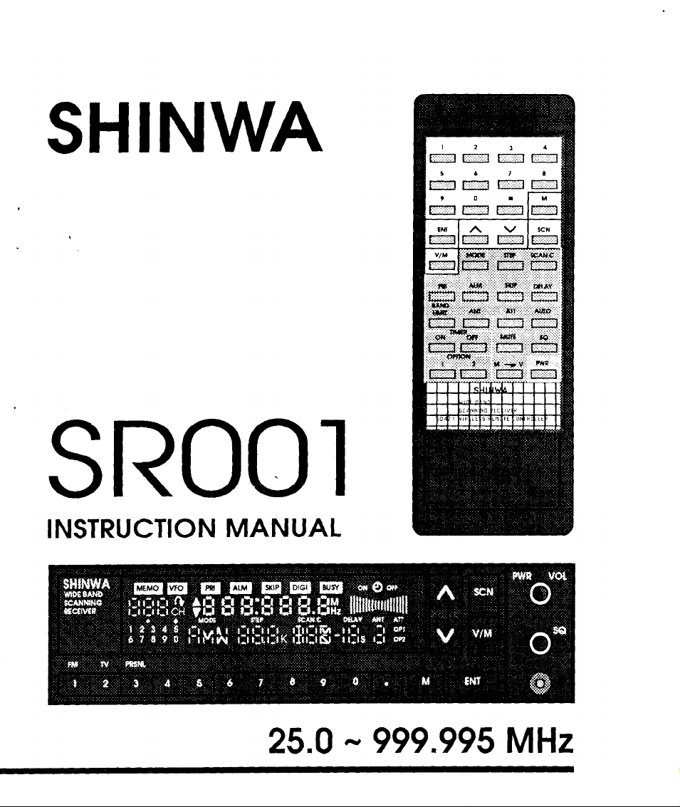
TABLE OF
INTRODUCTION
GETTING
POWER
ANTENNA
QUICK
CONTROL FUNCTIONS
REMOTE
OPERATION
STARTED
UNPACKING
MOUNTING BRACKET
INSTALLATION
CONNECTIONS
MOBILE POWER
BASE POWER
REFERENCE
QUICK
FRONT PANEL
DISPLAY
REAR PANEL
BATTERIES
FUNCTIONS
FACTORY
POWER
VFOMEMO MODE
SCAN
REFERENCE
CONTROL
PROGRAMMED
ON, VOLUME
SQUELCH CONTROL
MODE
VFO
SCANNING
MEMO
RESUME
CONNECTIONS
CONNECTIONS
SCANNING
SCANNING
CONTENTS
CHART
MODE
CONTROL, AND
Page
J
4
4
4
5
6
6
7
8
9
10
11
11
r3
tl
18
18
t9
22
22
22
23
25
25
26
26
COPY
SKIP
CLEAR
MEMO
BAND SCAN
TIMER MODE
PRIORTY
ALARM
RESET
OPTIONAL
FACTORY
FACTORY
SPECIFICATIONS
GENERAL
RECEryER
SROO1
QUICK
MEMO CHANNEL
MEMO
(ERASE)
GROUP SCAN
MODE
MODE
MICROPROCESSOR
RS.232C
PROGRAMMED MODE
PROGRAMMED
REFERENCE
TABLE
.
CONTINUED.
CHANNEL
MEMO
OF
CONTENTS
CHANNEL
MODE
CHART
CHART
Pase
29
29
3r
31
34
36
38
39
40
40
40
4l
42
42
43
45
INTRODUCTION
The
Shinwa
synthesized
service and
MHz and
each).
listening
provides 200
A full-featured wireless remote
receiver from
optimum
performance
o
a
o
a
o
a
o
o
o
a
o
Model
SR001
receiver
Wide Band
is
that
pleasure.
designed to
The
programmable
Scanning
provide
scanning
memory
receiver
channels
control
relaxation ofyour
the
of
Wid e-Band
High-Speed
received frequencies:
all
Frequency
Scanning
easy chair. The following features
Coverage
o 35-Ch / Sec in VFO Mode
|
200 MEMO Channels
25-Ch
i
Sec
in MEMO
(10
Groups of 20
Mode
Pre-Programmed Mode By Frequency
Programmable
.
.
MEMO
MEMO
. MEMO Band
t Resume
Timer
Alarm
(On
or
Priority
OfI)
Easy-To-Read MultiColor
for:
Scan
Channel
Scanning
Group Scanning
Scanning
Saan
Mode
Channel
Monitoring
LCD Display
Wireless Remote Control
Two Antenna
Lithium Battery Memory
Jacks for Optimum Antenna
Back-Up
Receiver is
you
with
covers
(10
is
also
included
Channels)
Segment
^,,,
I
a state-of-the-art,
years
of
dependable
25
through 999.995
groups
of20 channels
to operate the
provide
Selection
for
These features
available. Please
comfortable
combine
read
with the operation
achieve maximum
THANKYOU
performance
provide you
to
manual
this
FOR
with one of the finest
thoroughly so
programming
and
and
enjoyment while using the receiver.
CHOOSING THE
scanning receivers
you
that
will become familiar
examples.
This
will
SROO1 WIDE-BAND
help
and
you
SCANNING RECEIVER!
Note: Any information
intendedforcommercialpurposes. Pleasefollowallappiicablegovernmentregulgtionsthat
apply to radio frequency broadcasts and reception.
monitored on this receiver
is for
your
personal
use only and
is
not
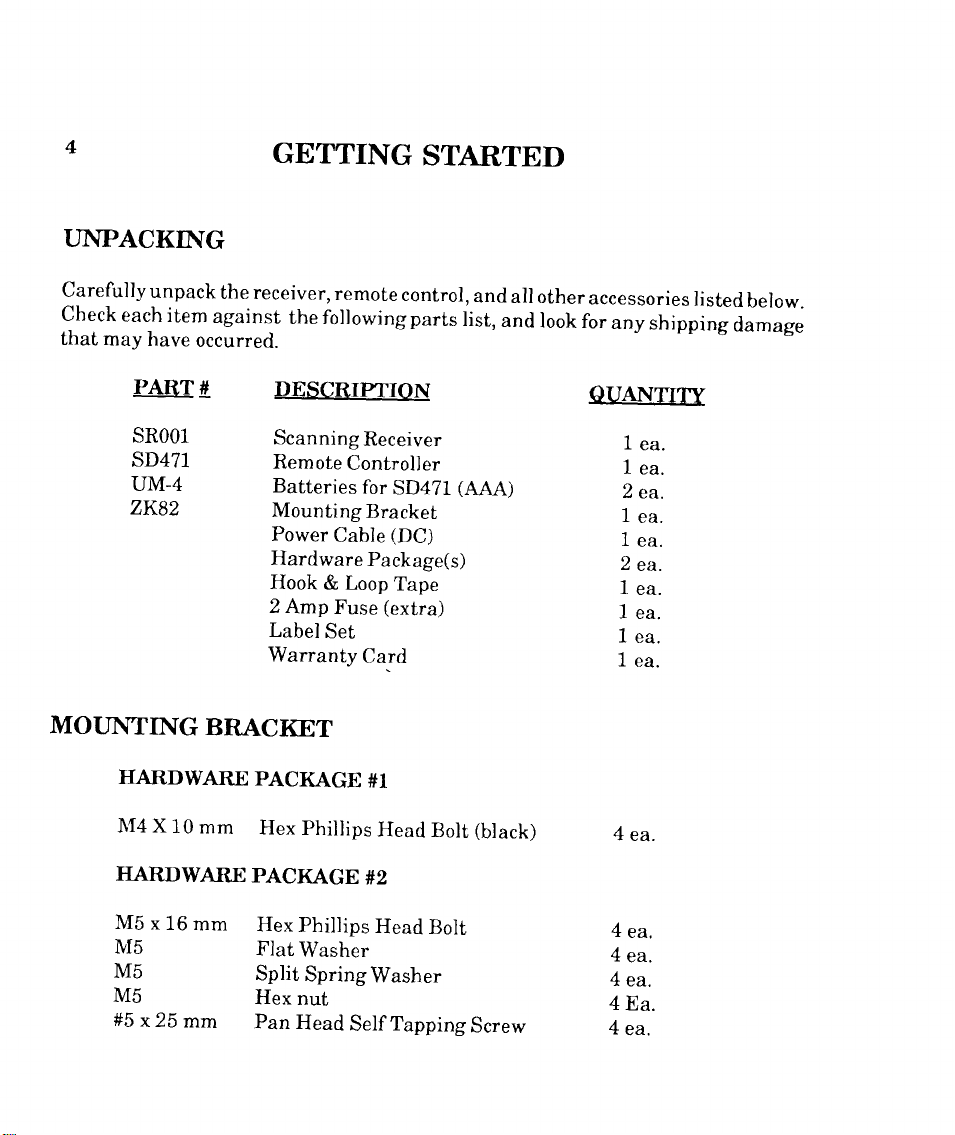
TINPACKING
GETTING
STARTED
Carefully
check
that
unpack
each item
may
have
PART
SROOl
SD471
UM-4
occurred.
d
zK82
MOTTIVTING
HARDWARE
X[4 X
BRACKET
10
mm
the receiver,
against
the following parts
DESCRIPTION
Scanning
Remote
Batteries
Mounting
Power
Hardware
Hook
2
Amp
Label
Warranty
PACKAGE
phillips
Hex
remote
Receiver
Controller
for
Bracket
Cable
Package(s)
& Loop
(extra)
Fuse
Set
Card
#1
Head
control,
SD471
(DC)
Tape
Bolt
and
list,
and
(AAA)
(black)
all other
look
accessories
for
any
shipping
OUANTTTY
1
ea.
1
ea.
2
ea.
1
ea.
1
ea.
2
ea.
1
ea.
1
ea.
1
ea.
1
ea.
4
ea.
listed
damage
below.
HARDWARE
M5
x
16
mm
NIs
M5
M5
#5
x 25
mm
PACKAGE
phillips
Hex
Flat
Washer
Split
SpringWasher
Hex
nut
Pan
Head
#2
Head
Self
Bolt
Tapping
Screw
4
ea,
4
ea.
4
ea.
4Ea.
4
ea.

INSTALI,ATION
The
SR001
performance.
and operate. However, it should have at least two
the rear heat
mounted
be
is
not
in
the
Receiver
It
sink
so
direct air
can be installed and used
should be
for
that
installed
ventilation and heat dissipation.
it
not interfere
does
flow ofa heater vent.
so the digital display and controls
with the safe
MOUNTING
BRACKET
MOBII.E
INSTATTATION
UNDER DASH BOARD
The
mounting
as a stand. If
holes as a template for
screws. Mount
receiver
remaining hardware in
bracket
you
desire
the bracket
to
the bracket
can
to
case
installed
be
permanently
determining the best
your
with
you
four
wish to
with the
top of
on
install
choice
of
(4)
black
change the
the bracket, use the mountingbracket
location to
supplied hardware.
hex screws
in
position
any
inches
operation
receiver,
the
mounbing
without
are
(50
If
used
mm)
air
of
space
in
a vehicle, it
of the vehicle
FIXED
INSTALLATION
or under the receiver
drill starting
(M4
x 10
location
holes
Then
mm).
at a later
affecting
easy to
around
should
and
for the
mount the
Save the
time.
its
see
You may
place
external speaker specified at BQ
available at
also wish
the speaker
your
authorized Shinrva
connect an optional external speaker which
to
in a more
convenient
(ohms)
Dealer.
may
allow
listening location.
such as the optional Shinwa Model
For
best results,
you
to
use an
ZP72l
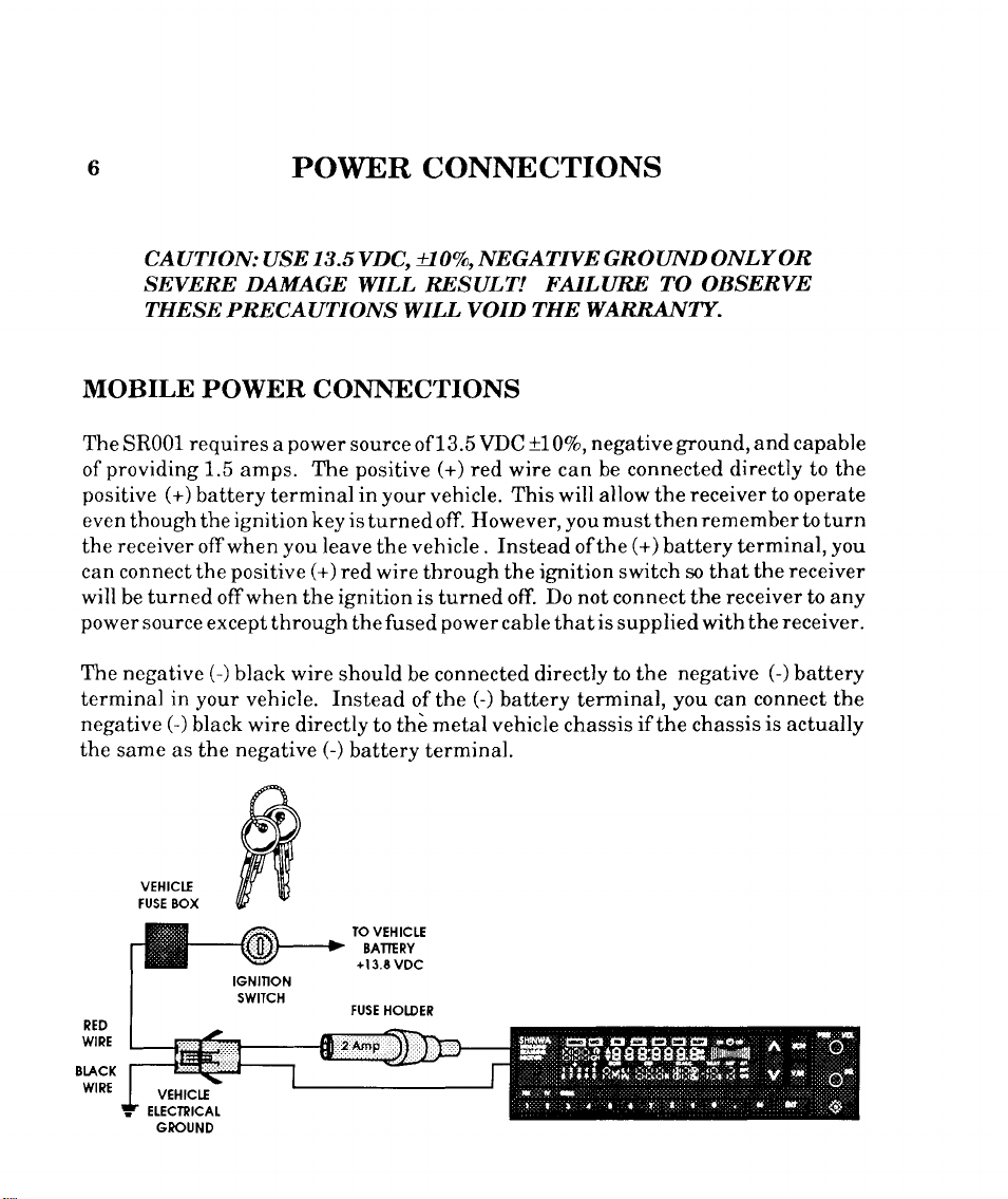
POWER
CONNECTIONS
CAUTION:
SEVERE DAMAGE
TH E
SB PRECAUTIONS W ILL V OID
MOBILE POWER
The
SR001
providing
of
positive
eventhoughtheignitionkeyisturnedoff.
receiver
the
can connect the
will
be
power
The negative
terminal
negative
the
same as the
requires
1.5
amps.
(+)
battery terminal
offwhen
positive
turned
source
offwhen the
except
(-)
black
in your
(-)
vehicle.
black wire directly
negative
13.5VDC,
USE
WILL RESULT!
CONNECTIONS
power
a
you
through
source of 13.5 VDC
positive
The
your
in
leave
the vehicle .
(+)
red
wire
ignition
the fused
wire
should
Instead
to the
(-)
battery terminal.
!70Vo, NEGATM
(+)
red
vehicle.
However,youmustthenremembertoturn
through
is turned off. Do not connect the
power
be connected
(-)
of the
metal vehicle
GROUND ONLY
FAILURE
TH E WARRANTY.
+707o,
negative
wire can be
This
will
Instead
ignition switch so that
the
cable that
directly
battery
connected directly to the
allow the
(+)
the
of
is
supplied with
to the
terminal,
if
chassis
the chassis
OR
T:O
OBSERVE
ground,
and capable
receiver to operate
battery terminal,
receiver
the
receiver to any
receiver.
the
negative
you
(-)
connect the
can
is
battery
actually
you
RED
WIRE
Bt-ACX
WIRE
vEHtctf
rUSE BOX
IO VEHICTE
BAITERY
+13.E
VDC
TUSE
HOIDER
7'
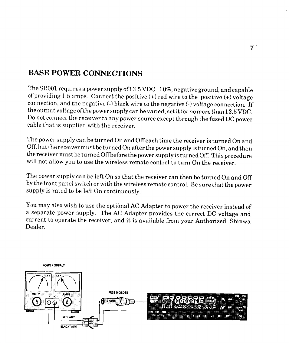
BASE
The
of
connection,
the
Do
cable
The
off,
the receiver
will
The
by
supply
You
a
separate
current
Dealer.
POWER
sR001 requires
providing
output
not
that
power
butthereceivermust
not
power
front panel
the
may
1.5
and
voltage
connect
is
supplied
supply
must
allow you
supply
rated
is
also
wish
power
to
operate
the receiver
to
CONNECTIONS
power
a
amps.
the negative
of
the
can
be
turned
to
use
can
switch
be left
to
use the
supply.
the
supply
Connect
power
with
be
turned On
be turned
the
be left
or
On continuously.
receiver,
the
(-)
black wire
supply
to
any
the receiver.
Offbefore
wireless remote
On so
rvith
the
optional
The AC
and
of 13.5
vD
positive
to
can be varied,
power
source except
and
Offeach
on
afterthe
power
the
that
the receiver
rvireless
AC
Adapter
Adapter
is
it
available from your
+\\qn,negative
C
(+)
red
wire to
tbe negative
set it for no
through
time the
power
supplyisturned
supply is
control
remote
provides
turned
to turn
can
then
control. Be sure
power
to
the correct
ground,
positive
the
(-)
voltage
more
the fused
receiver
is
Off.
on
the
be turned
the receiver
DC
Authorized
and capable
(+)
voltage
connection.
than 13.5
turned
on,
This
receiver.
that
voltage
VDC.
power
DC
On
andthen
procedure
On
and
power
the
instead
and
Shinwa
If
and
Off
of
POWET
sUPPI.Y
8
All
antennas
designed
broadband
narrow
greater
compared to
strength
tions
Your
receive.
that
different
vehicle
signal
to
bands of frequency ranges.
received
over
gain,
for
choice of
Ideally,
are available in
antenna
mounting.
strength on the
ANTENNA
are designed for
be
extremely narrow
to
cover a broad frequency
signal strength
a broadband
a broader range offrequencies.
directional
antenna(s)
you
should consider
the market
companies,
You
may
particular
use
on specific frequency ranges. Antennas
band
to cover
range,
A narrow
on
antenna
or omni-directional
make
will
place.
and
choice
narrow
the
that typically
a significant difference in
one ofthe
These
are available
two different antennas
frequencies you
a very narrow
or dual-band
band antenna will typically
frequency range it is
offers a
Each
antenna
signal
antennas
patterns,
specially
for
base station
are interested in
frequency range,
to cover two different
designed
lower received
has
its own
mounting.
and
the sigaal strength
designed
are
so
scanner
manufactured
mounting
you
receive
monitoring.
are also
very
provide
for
as
signal
specifica-
you
antennas
many
by
and
maximum
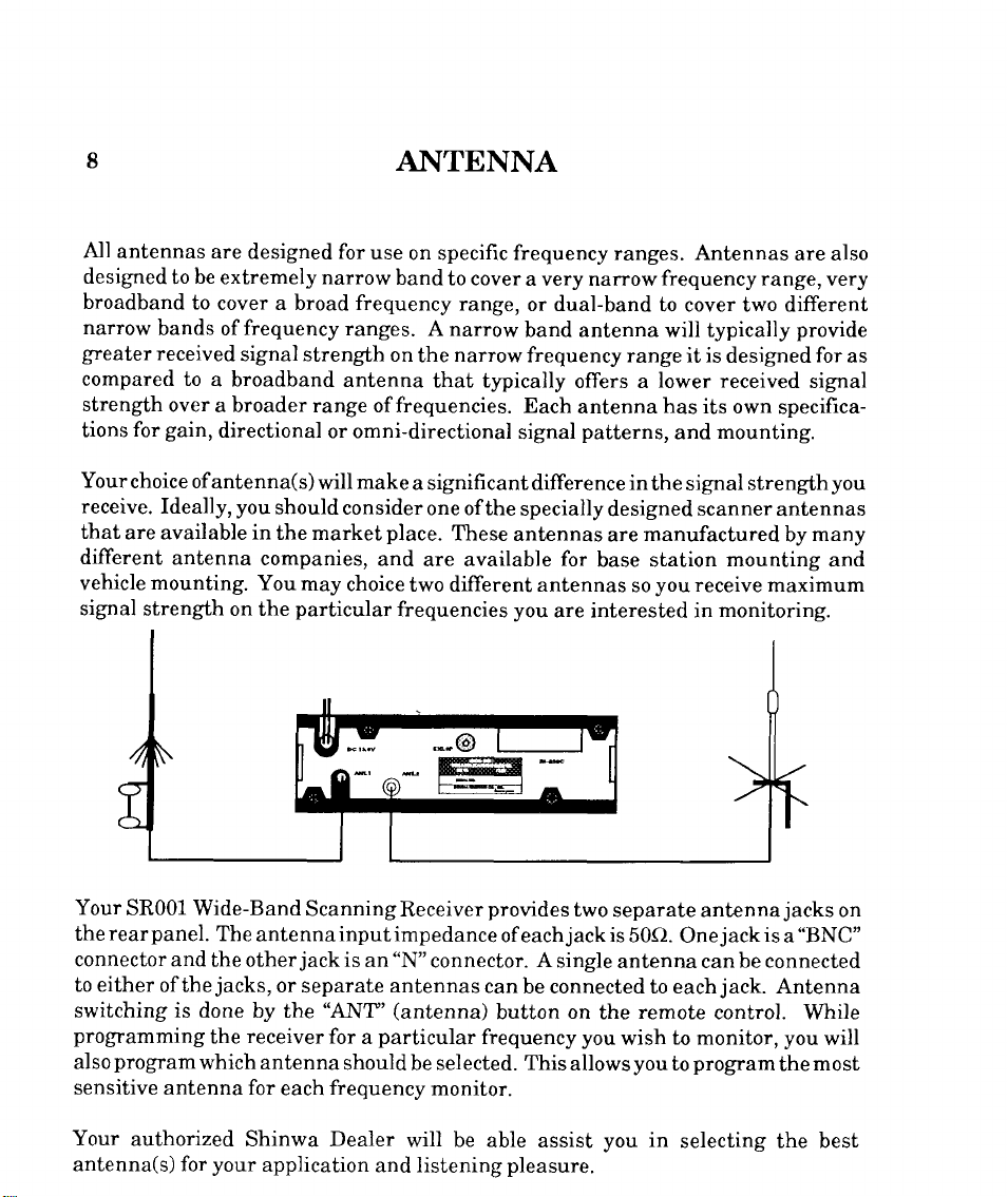
Your
SR001 Wide-Band
panel.
rear
the
connector and
to either
switching is
programming
also
sensitive
Your
antenna(s) for
ofthe
program
antenna for
authorized
done by the "ANT'
which
-;
ScanningReceiverprovides
The
antenna
the otherjack is
jacks,
receiver
the
antenna
Shinwa Dealer
your
application
or
separate
for
frequency
each
input impedance
should
.-.@
ffi*
|_-GL"c=l
O
"N"
an
a
connector. A single
antennas
(antenna)
particular
selected. This
be
monitor.
will be
and listening
;r
two
separate antenna
jack
of each
can
be connected to each
button
frequency
able assist
pleasure.
is
50O.
antenna can
on
the
you
wish
allows
you in
you
jack
One
be connected
jack.
remote
control. While
to monitor,
program
to
selecting the best
jacks
"BNC"
is
a
Antenna
you
will
most
the
on

This
chartisintended
with all
functions
maximum
repeated
receiver.
features
and
performance
in
QUICK
as
functions
and
perform
the back ofthe manual in case
REFERENCE CHART
aquick referenceafteryouhave
receiver.
of the
of
all
and enjoyment while using
programming
the
becomecompletelyfamiliar
Please read
examples to
receiver. The chart is also
the
you
wish to cut-it-out and
through
help
all the control
you
achieve
keep it
with
I
the
1.
2.
Indicates
is displayed on the LCD
Crystal
Indicates
front
should be
what mode or
Display)
what button on the
panel
pressed.
remote
or
of the
control
function
(Liquid
receiver.

SROO1
QUICK
REFERENCE
CIIART
FUNCTION
ENTER
A FRE().
INTO
TIIE
w'o
CIL\NGE TITE
FUNCTION
A PREVIOUSLY
ENTL'RED
ENTERAT.RDQ
INTO
MEMOITY'MEMO''
CTIANNF]L
R.ECALLING
MEMORY
CIIANNET,WHEN
INITTO'IMODE
RECAIIINGA
MEMORY
CIIANNEL WHEN
''ME]!TO''
IN
1'0 SCIIN
OF
FIREQ.
A
A
MODE
OPERATION
PRESS'EI{I''
ENTER
Tr[t FREQ.
PRESS'ENT''
PRESS'MODN'"
'STEP"
TITEN
SELECT
ENTER
PRESS
ENTER MEM CII
PRESS'EN'I';
'r6N'1r'&
PRESS'TNT'
ENTEIT MEM CH
PRESS'ENT"; OR
'ENTil g rrfirr
PRESS'SCAI]""
OR'ANT''
CIIANGE
FUNCTION
TIIE FREQ.,
PRESS'M",
MEM CII
PRESS'ENT'
'V/nif"'Slilf"
rr n 'r
OR
OII
OR
rr { rr
tt
!f
PRIISS
PRESS
#, &
OR
"V'r
"V"
tr
#,
#, &
MODE
'vFo"
'MODE",
'STEP"
OR
'ANT''
'MEMO''
OR
ilat
'vFO"
'TYIEMO"
"a"
OR
ilV il
ITEMARKS
SCANNING
AVAILABLE
EIVI'IiRING A
FREQ.
NOT
POSSIBIJ
WHEN
DISPI.AYED
FUNCTION
POSSIBLE WHEN
TIIF
FI,1\SIIING
POSSItsLE IF
TTIE
NOT DISPLAYED
I'OSSIBLE
TIIF
NOT DISPLAYED
PRI'SS'SCA]Y'
ACNIN
TTIIS
NOT
WHEN
TTIE
"."
IS
IS
"o"
fS
"o"
IF
IS
"o"
TO STOI'
MODE
IS
CTIANGE TTM SCAN
I.'UNCTION
RESUME
SETTING THE
"oIY'OR
FUNCTION
OF TIIE
SCAN
MODE
"OFtr''
TIMER
PRESS'SCAN.C''
TO SELECT
'AUD",
A SCAN
PRESS TIMER
"OiV'OR
ENTER
PRESS'ENT"
OR
''CAFI'"
''rIM"
MODE
"OFI.-'
TIME,
AS
"cAIl",
''AUI)'"
OR
''TIM'
CA]\'BE CHANGED
"c"
TIIIS
FUNCTION
WIIILE
MODE
MAXIMUM
99
HRS & 59 MIN
FROM
PRESEIYT
INAIIY
TTME IS
THE
TIME
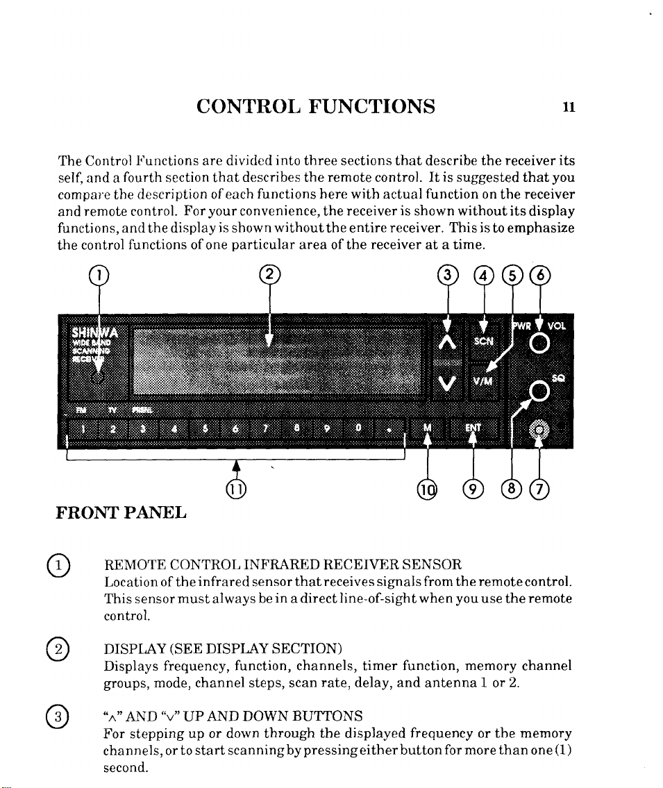
CONTROL FUNCTIONS
ll
The
Control
self, and a
compale the
remote control.
and
functions,andthedisplayisshownwithouttheentirereceiver.
control
the
Functions are
fourth
section that describes
description of each
For your
functions of
one
divided
particular
into
three sections that
the remote control. It
functions here
convenience, the receiver
area of the
with actual
receiver
describe
is
suggested that
function
is
shown without its
Thisistoemphasize
at a time.
FRONT PANEL
the receiver
you
receiver
on the
display
its
REMOTE
Location
This sensor
control.
DISPI,AY
Displays
groups, mode, channel steps, scan
"n" AND
For stepping
channels,
second.
CONTROL
infrared
of the
must
(SEE
frequency,
"v"
IJP
up or dolvn through
start
or to
INFRARED
sensor
always
DISPI,AY SECTION)
function, channels, timer function,
AND DOWN
scanningby
thatreceives signals from the
in
be
a direct
BUTTONS
pressingeither
RECEIVER
line-of-sight
rate,
delay,
the
displayed
SENSOR
remote
you
when
and
antennal or
frequency or tbe memory
button
use
memory
for more than
control.
remote
the
channel
2.
one
(1)
t2
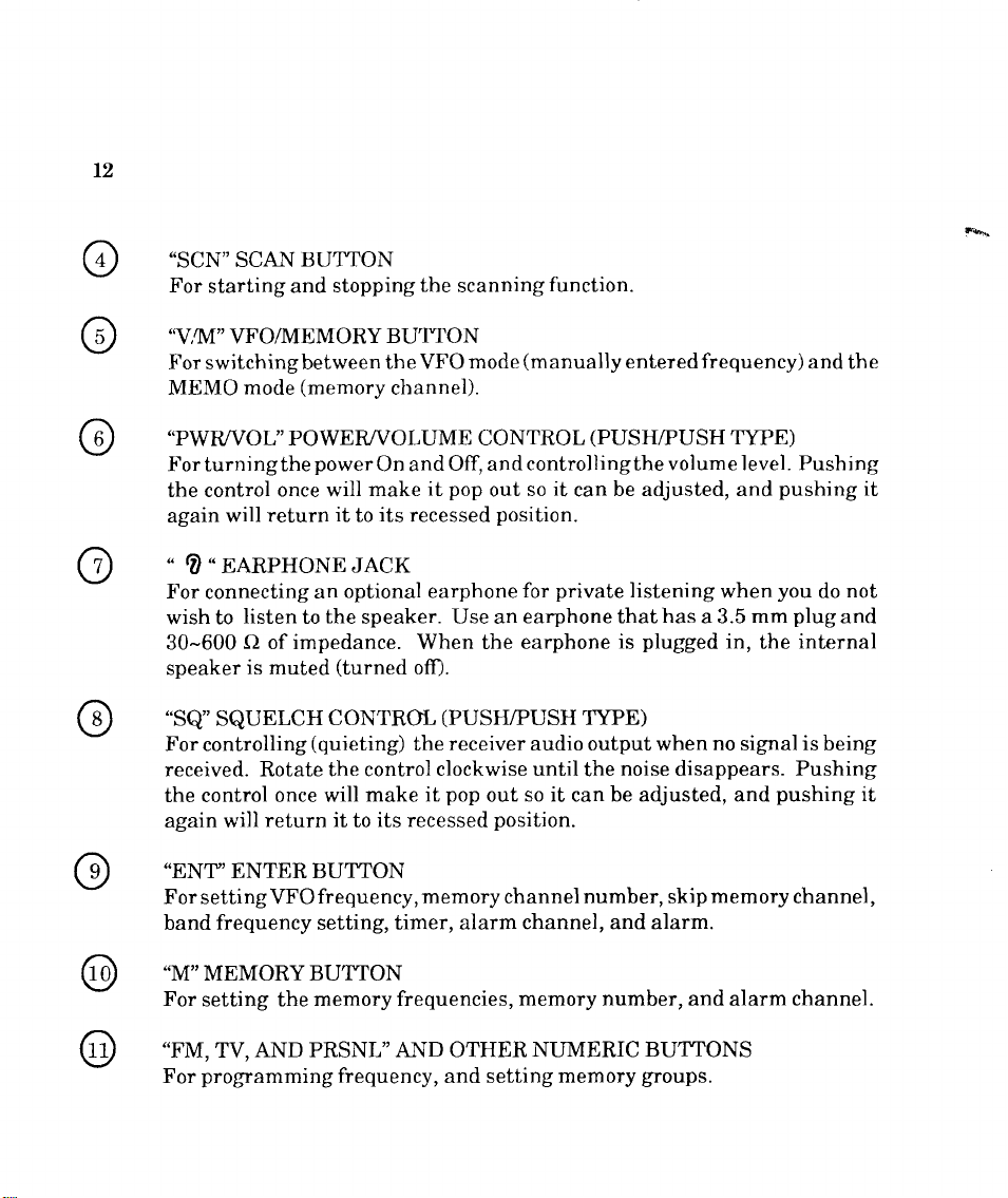
"SCN" SCAN
For
starting and
.\.,M"
VFO/MEMORY
For switchingbetween
MEMO
"PWR,/VO L" POWE R,/VO
Forturningthe
the control
again will
"
?"EARPHONEJACK
For
connecting
wish to
30-600
speaker
"SQ"
SQUELCH
For controlling
received. Rotate the control
the control
again will
"ENTO'ENTER BUTTON
For settingVFOfrequency,
frequency
band
BUTTON
stopping
(memory
mode
powerOn
once will
return
listen
O
of impedance. When the
is muted
return it
it
optional earphone
an
the
to
(turned
CONTROL
(quieting)
once will
setting,
to
to
the
BUTTON
the VFO
clrannel).
LUME
and
it
make
its
recessed
speaker. IJse an
off).
the
make it
its
recessed
memory
timer, alarm
scanning
mode
C O
Off, and
pop
(PUSH/PUSH
receiver
clockwise until
pop
function.
(manually
NTRO L
controllingthe volume level. Pushing
it
so
out
position.
private
for
earphone that
earphone
audio output when
so it
out
position.
channel
channel, and alarm.
enteredfrequency)
(
PUS H/PU
be adjusted, and
can
listening
is
TYPE)
noise
the
be adjusted, and
can
number,
SH
has
a 3.5
plugged
disappears.
skip
TYI'E
pushing
you
when
mm
in,
the
no
signal
pushing
memory
and the
)
not
do
plug
and
internal
is
being
Pushing
channel,
it
it
"M" MEMORY BUTTON
For
setting the
"FM,
TV,
programming frequency,
For
memory frequencies,
AND PRSNL'AND OTHER NIIMERIC
memory number, and
and setbing
memory
alarm
BUTTONS
groups.
channel.
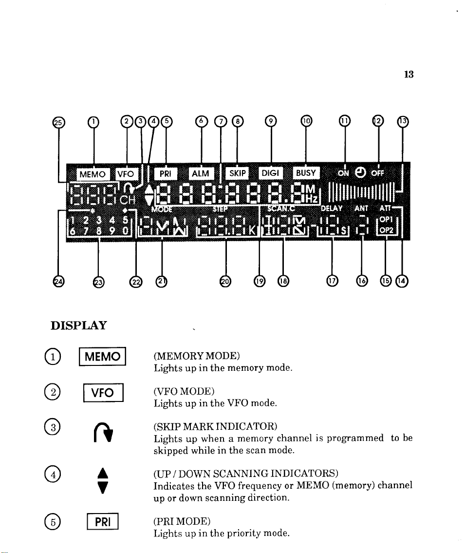
DISPLAY
l3
o
@
@
@
@
lMEMol
vFol
f
ft
A
V
E
(MEMORYMODE)
memory
in
up
Lights
(VFO
MODE)
Lights up
(SKIP
Lights up when
skipped
(LP
DOWN SCANNING
/
Indicates
down
up or
(PRI
MODE)
Lights
the
in
VFO
the
MARKINDICATOR)
a
in the scan
while
the VFO
scanning
priority mode.
in
up
the
mode.
mode.
memory
frequency or
direction.
channel
mode.
INDICATORS)
is
MEMO
programmed
(memory)
channel
to
be
14
@
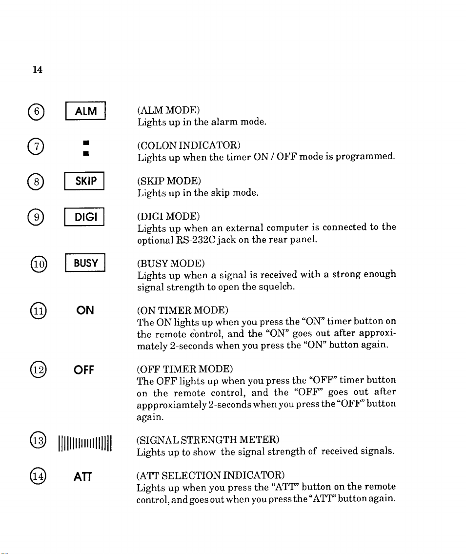
IALMI
(AIM
MODE)
Lights up
in
the
alarm
mode.
o
@
@
@
@
I
I
sKrPl
I
prcll
I
Brrsvl
I
ON
OFF
(COLON
Lights up
(SKIP
Lights up
(DTGI
Lights up
optional
(BUSY
Lights
signal strength
(ON
The
the
mately
(OFF
The OFF
on the
appproxiamtely
again.
INDICATOR)
the timer
when
MODE)
in
skip
the
MODE)
an external
when
RS-232C
MODE)
up when
TIMER
lights up when
ON
remote cbntrol,
2-seconds when
TIMER
lights up
remote
a signal
to open
MODE)
MODE)
control,
2-seconds
mode.
jack
on
the squelch.
you
and the
you
when
/ OFF
ON
computer
panel.
rear
the
is received
press
the
goes
"ON"
press
the
press
you
and the
when
the
you
"OFF"
press
programmed.
is
mode
is connected
a strong
with
"ON" timer
out after
"ON" button
"OFF' timer
goes
"OFF" button
the
the
to
enough
button
out after
on
approxi-
again.
button
@
llllnr*rrrllll
ATT
(SIGNAL
Lights up to
(ATT
Lights up when
control, and
STRENGTH
show
SELECTION
goes
METER)
the signal
INDICATOR)
press
you
outwhen
the
youpress
received sigaals.
strength
"ATT''button
of
"ATT''button
the
on
the
remote
again.
 Loading...