


SHINOBI
Gaia404 / 408 / 416-60 / 416-120
Cha ssis Asse mbly Guide
Version 1.0
Published August 2009
Copyright©2009 ASRock INC. All rights reserved.
Copyright©2009 Huper Laboratories CO., LTD. All rights reserved.
11
1
11
Copyright Notice:Copyright Notice:
Copyright Notice:
Copyright Notice:Copyright Notice:
No part of this manual may be reproduced, transcribed, transmitted, or translated in
any language, in any form or by any means without the written consent of hupeLab
and ASRock Inc., except duplication of documentation by the purchaser for backup
purpose.
Products and corporate names appearing in this manual may or may not be registered trademarks or copyrights of their respective companies, and are used only for
identification or explanation and to the owners’ benefit without intent to infringe.
Disclaimer:Disclaimer:
Disclaimer:
Disclaimer:Disclaimer:
Specifications and inf ormation contained in this manual are provided for information al
use only. It is subject to change without notice and should not be recognized as a
commitment by huperLab and ASRock. huperLab and ASRock assume no responsibility for any errors or omissions that may appear in this manual. With respect to the
contents of this manual, huperLab and ASRock do not provide any kind of warranty,
either expressed or implied.
In no event should huperLab and ASRock, its directors, of ficers, e mployees, or agents
be liable for any indirect, special, incidental, or consequential damages (including
damages for loss of profits, loss of business, loss of data, interruption of business and
the like).
(EC conformity marking)
This device complies with Part 15 of the FCC Rules. Operation is subject to the
following two conditions:
(1) This device may not cause harmful interference, and
(2) This device must accept any interference received, including interference that
may cause undesired operation.
CALIFORNIA, USA ONLY
The Lithium battery adopted on this motherboard contains Perchlorate, a toxic
substance controlled in Perchlorate Best Management Practices (BMP) regulations
passed by the California Legislature. When you discard the Lithium battery in
California, USA, please follow the related regulations in advance.
“Perchlorate Material-special handling may apply, see
www.dtsc.ca.gov/hazardouswaste/perchlorate”
For more product details, please visit ASRock website at www.asrock.com
22
2
22

ContentsContents
Contents
ContentsContents
I. IntroductionI. Introduction
I. Introduction
I. IntroductionI. Introduction
I.1 Package Contents .......................................................... 5
I.2 Recommended Tools...................................................... 5
I.3 Recommended Working Environment ........................... 5
II. RII. R
emoval of Chassis Componentsemoval of Chassis Components
II. R
emoval of Chassis Components
II. RII. R
emoval of Chassis Componentsemoval of Chassis Components
II.1 Chassis Internal View .................................................... 6
Figure 1. Inside Motherboard.................................................................. 6
II.2 Removal of Modules Inside Chassis............................. 7
Figure 2. Chassis Cover Removal .......................................................... 7
Figure 3. Opened Chassis...................................................................... 7
Figure 4. Fan, SSD Bracket, HDD Bracket Removal.............................. 8
Figure 5. Cold-Swap Removal ................................................................ 9
Figure 6. BNC Board Removal ............................................................... 9
II.3 Comparison ................................................................... 10
Figure 7. Comparison of Before and After .............................................. 10
II. Motherboard InstallationII. Motherboard Installation
II. Motherboard Installation
II. Motherboard InstallationII. Motherboard Installation
III.1 Motherboard Configuration .......................................... 11
Figure 8. Motherboard Configuration...................................................... 11
III.2 Motherboard Installation............................................... 12
Figure 9. Motherboard Installation .......................................................... 12
Figure 10. Connect ATX PSU ................................................................. 13
Figure 11. BNC Board Installation .......................................................... 13
Figure 12. Cold-Swap, SSD Bracket Installation .................................... 14
Hardware Information & Installation ....................................................... 15
Figure 13. Optinal Hard Drive Installation.............................................. 16
Figure 14. Fan Module Installation......................................................... 17
Figure 15. Front Bezel Installation .......................................................... 18
Figure 16. Chassis Cover Installation ................................................... 18
............................................................................................................
......................................................
............................................................................................................
........................................
....................
........................................
..................................................................
.................................
..................................................................
4 4
4
4 4
6 6
6
6 6
11 11
11
11 11
33
3
33

I. IntroductionI. Introduction
I. Introduction
I. IntroductionI. Introduction
Thank you for purchasing huperLab
reliable motherboard produced under huperLab’s consistently stringent quality control.
It delivers excellent performance with robust design conforming to huperLab’s commitment to quality and endurance.
This is an illustrated guide describes in details to instruct you assemble your own
computer. Part 1 contain configuration of the Chassis and step-by-step guide to the
hardware removal. Part 2 contain the configuration of the motherboard and step-bystep assembly guide to the system installation.
Gaia404 / Gaia408 / Gaia416
motherboard, a
Pre-removal / installation Precautions
Pay attention to the following precautions before you install motherboard components or change any motherboard settings.
1. Unplug the power cord from the wall socket before touching any component.
2. T o avoid damaging the motherboard components due to static ele ctricity, NEVER
place your motherboard directly on the carpet or the like. Also remember to use
a grounded wrist strap or touch a safety grounded object before you handle
components.
3. Hold components by the edges and do not touch the ICs.
4. Whenever you uninstall any component, place it on a grounded antistatic pad or
in the bag that comes with the component.
5. The motherboard and chassis a ccessories contain senitive components. Therefore,
make sure to store unused items in a dust-free and anti static environment to
lower the chance of electro-magnetic interference between them. Dust can affect
the performance of the system.
44
4
44
I.1 PI.1 P
ackack
I.1 P
I.1 PI.1 P
Motherboard Accessories
Chassis Accessorie s
20 x Screws
Fan Module
BNC Board
BNC Bracket
HDD Cage
SSD Bracket
I.2 RI.2 R
I.2 R
I.2 RI.2 R
age Contentsage Contents
ack
age Contents
ackack
age Contentsage Contents
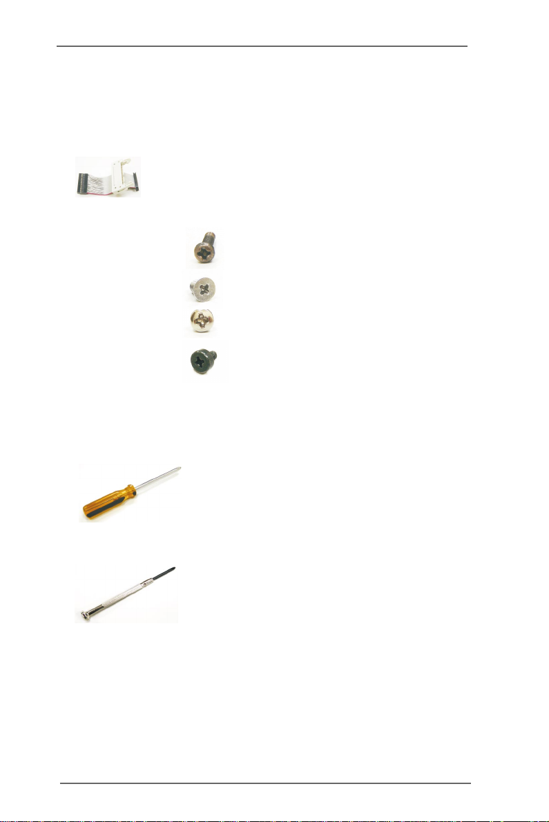
4 x Screws (SCREW M3*5L (F) W-ZN #2)
1 x BNC Card Cable
(SCREW M3*12L (P) #2)
(SCREW M3*5L (F) W-ZN #1)
HDD Bracket
Cold-swap Bay
ecommended Tecommended T
ecommended T
ecommended Tecommended T
Philips head Screwdriver (Or Star Screwdriver)
oolsools
ools
oolsools
(SCREW M3*5L (F) W-ZN #2)
(For Optional SATA Hard Drive)
Flat head Screwdriver
Magnatized Screwdriver (Optional)
Forceps (for pulling out jumpers and screws) (Optional)
I.3 RI.3 R
ecommended Wecommended W
I.3 R
ecommended W
I.3 RI.3 R
ecommended Wecommended W
In environments with ambient temperatures between 0C and 40C.
A flat surface and enough space to move is available when the system is
assembled.
orking Environemntorking Environemnt
orking Environemnt
orking Environemntorking Environemnt
55
5
55
II. PII. P
arar
II. P
II. PII. P
AURA H304 / AURA H308 / AURA H316-60 / AURA H316-120
DVR.
t One Rt One R
ar
t One R
arar
t One Rt One R
emoval of Chassisemoval of Chassis
emoval of Chassis
emoval of Chassisemoval of Chassis
ComponentsComponents
Components
ComponentsComponents
Intelligent Hybrid
II.1 Chassis Internal ViewII.1 Chassis Internal View
II.1 Chassis Internal View
II.1 Chassis Internal ViewII.1 Chassis Internal View
1
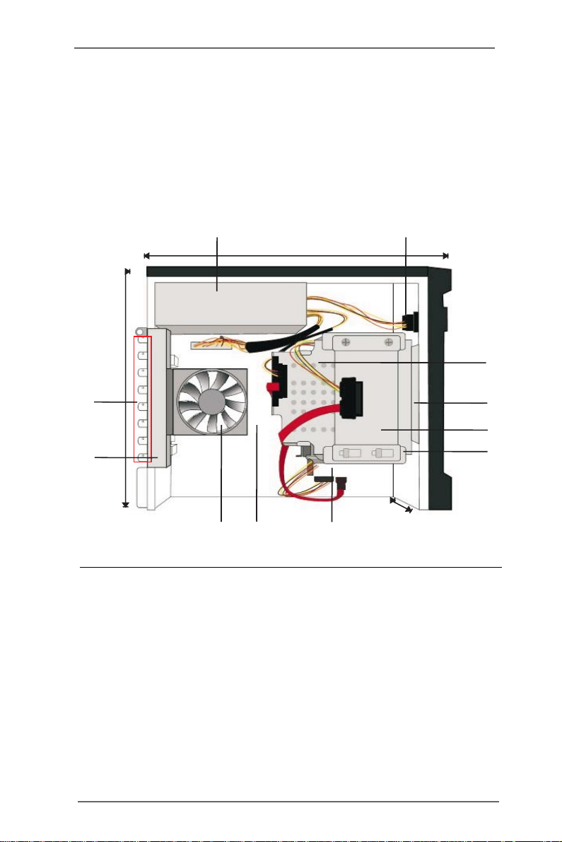
31.0cm (12.2in)
28.5cm (11.2in)
11
10
8
Figure 1. Inside the Chassis
1. Power Supply
2. A/C Power Device
3. Cold-Swap Bay for SATA Hard Drive
4. Hard-Disk Drive Bracket
5. SSD Bracket
6. Hard-Disk Drive Cage
7. Internal SATA Hard Drive bay
8. System Board
9. System Cooling Fan Module
10. BNC Board with Lightning Protection
11. BNC Ports
10.2cm (4.0in)
79
4
2
34
5 6
66
6
66

II.2 RII.2 R
emoval of modules inside Chassisemoval of modules inside Chassis
II.2 R
emoval of modules inside Chassis
II.2 RII.2 R
emoval of modules inside Chassisemoval of modules inside Chassis
* Please make sure to disconnect power supply and peripherals before
removing the system components.
* Keep all the screws in a secure place for later use.
Step 1. Remove the chassis cover. Remove three screws
securing the chassis cover to the BNC board.
Front
Back
Figure 2.Chassis Cover Removal
Step 2. Carefully slide the chassis cover back and up with the rear
panel facing you. Set aside the chassis cover.
Figure 3. Opened Chassis
77
7
77

Step 3. Remove the fan module. Remove one flat screws securing
the fan to the BNC board and two screws securing the fan
to the cold-swap bay. See Figure 4.
Step 4. Remove the SSD bracket by remove two screws securing
the SSD bracket to the HDD cage. Push the bracket away
from the securing hocks before lift up the bracket.
Step 3
Step 4
Step 5
Figure 4. Fan, SSD bracket, HDD bracket removal
88
8
88

Step 5. Remove the front bezel by disconnect the cover hooks.
Then, remove two screws securing the HDD bracket to
the cold-swap bay. See Figure 4.
*Move the cables around while removing the components.
*Prevent the cables from rubbing each other.
*This will harm the cables.
Step 6. Remove the cold-swap bay. Remove seven screws
securing the cold-swap bay to the HDD cage. Then,
gentally push one end of the cold swap bay to the side that
is facing out.
Front
Figure 5. Cold-Swap Bay Removal
99
9
99

Step 6. Remove the BNC board. Remove six screws securing
the BNC board to the chassis.
Figure 6. BNC Board Removal
III.3 ComparisonIII.3 Comparison
III.3 Comparison
III.3 ComparisonIII.3 Comparison
BefBef
oror
or
oror
ee
e
ee
Bef
BefBef
Figure 7. Comparison of before and after
1010
10
1010
AfterAfter
After
AfterAfter

III. Motherboard InstallationIII. Motherboard Installation
III. Motherboard Installation
III. Motherboard InstallationIII. Motherboard Installation
Gaia404 (A330GC-H4) / Gaia408 (A330GC-H8) / Gaia416-60 (A330GC-H16-60) /
Gaia416-120 (A330GC-H16-120) huperVision 4000 DSS Server Board.
III.1 MotherboardIII.1 Motherboard
III.1 Motherboard
III.1 MotherboardIII.1 Motherboard
ConfigurationConfiguration
Configuration
ConfigurationConfiguration
1
17.0cm (6.7 in)
Keyboard
Mouse
PS2
PS2
USB 2.0
T: USB 0
B: USB 1
USB 2.0
T: USB 2
B: USB 3
Bottom:
Mic In
6
CLRCMOS1
CMOS Battery
Top:
RJ-45
Top:
RJ-45
Line Out
Center:
Line In
Top:
AUDIO
CODEC
SYS_FAN1
VGA1
AVIN PORT
P9
P1
COM1
COM1
Powered by
P5
1
1
P7
Super
I/O
PCIE1
Figure 8. Motherboard Configuration
DSS Serve Board
FSB800
DDRII_2 (64 bit, 240-pin module)
FSB800
DDRII_1 (64 bit, 240-pin module)
huperLab
A330GC-H16
P8
RoHS
Intel
ICH7
Gaia416
4Mb
BIOS
1
P1
SATAII_4
SATAII_3
PLED PWRBTN
1
1
1
1
PS2_USB_PWR1
HDLED RESET
USB6_7
USB6_7
USB4_5
IDE1
IDE1
17.0cm (6.7 in)
17.0cm (6.7 in)
SATAII_2
23 45
SATAII_1
NB_FAN1
PANEL1
1. ATX Power Supply
2. SATAII Connector (SATAII_2; Red)
3. SATAII Connector (SATAII_1; Red)
4. System Panel Header (PANEL1; Orange)
5. USB 2.0 Header (USB 6_7; Blue)
6. Video In (P5)
1111
11
1111

III.2 MotherboardIII.2 Motherboard
III.2 Motherboard
III.2 MotherboardIII.2 Motherboard
*Place screws into the holes indicated by circles to secure the
motherboard to the chassis.
*Do not over-tighten the screws! Doing so may damage the chassis
and motherboard.
*Please make sure to disconnect power supply and peripherals
before removing the system components.
* Keep all the screws in a secure place for later use.
*Do not turn on power during the whole installation process.
InstallationInstallation
Installation
InstallationInstallation
Step 1. Place the motherboard on the system board. Firstly, match
the mounting holes on the motherboard with the metal
spacers H2 & H4. Press four corners gently and fasten four
screws to secure the motherboard to the mounting plate.
H2
H4
Figure 9. Motherboard Installation
1212
12
1212

Step 2. Connect the ATX power connector from the ATX power
supply to the motherboard.
Figure 10. Connect ATX PSU
Step 3. Install the BNC board to the motherboard. Insert the BNC
card cable to video in (see P.11 No.6).
Side
Figure 11. BNC board Installation
1313
13
1313

Step 4. Install the cold-swap bay. Gentally push half way of the
cold swap bay into the HDD cage. Connect the SATA cable
to the SATA II_2 connector(see P.11 No. 2) and connect the
power connector from the ATX power supply on one side of
the HDD cage. See Figure 12.
Step 5. Install the SSD bracket by place the bracket on the top of
HDD cage and secure the hooks. Connect the SATA cable
to the SATA II_1 connector(see P.11 No. 3) and connect the
power connector from the ATX power supply on another
side of the HDD cage. Now, push the cold-swap bay all the
way into the HDD cage. Fasten seven screws to secure the
cold-swap and two screws to secure the SSD bracket to the
HDD cage. See Figure 12.
SATAI I 2_
Figure 12. Cold-Swap, SSD bracket installation
1414
14
1414
Step 4
SATAI I 1_
Step 5

Hardware Information & Installation:
1.If your system includes the optional internal SSD hard drive, it is
suggested to install the machine’s operating system on the SSD
hard drive and store the video recording data on one or two hard
drive.
2.If your system does not include the optional internal SSD hard
drive and plan to install two hard drives, it is suggested to install
the machine¡¦ s operating system on the internal SATA hard drive
and store the video recording data on the cold swap hard drive.
3.If your system does not include the optional internal SSD hard
drive and only pla n to install one SATA hard drive, it is suggested
to utilize the cold swa p hard drive bay first.
Cold swap hard drive
Internal SATA hard drive
SA TA Cable
1515
15
1515

Step 6. Optional hard drive installation.
Installing cold swap hard drive-- Insert the hard drive to the
HDD bracket a nd fasten two screws on each side to secure
the bracket to the cold swap bay.
Installing internal SATA hard drive-- Fa sten two screws on
two side of the hard drive before insert the hard drive to the
HDD cage. The screws will secure the hard drive on the
HDD cage. Plug one end of the SATA cable to the hard
drive and another end to the SATAII_3 connector.
SATA II _3
Step 6
Figure 13. Optional Hard Drive Installation
1616
16
1616

Step 7. Install the fan module. Connect CPU fan to CPU fan
connector and fasten one flat screws to secure the fan
module to the BNC board and two screws to the cold-swap
bay. See Figure 12.
*Move the cables around while installing the components.
*Prevent the cables from rubbing each other.
*This will harm the cables.
Step 7
Figure 14. Fan Module Installation
1717
17
1717

Step 8. Install the front bezel. Make sure all the hooks clicked.
Figure 15. Front bezel installation
Step 9. Install the chassis cover. Gentally slide the chassis cover
toward the front bezel. Fasten three screws to secure the
chassis cover to BNC board.
Figure 16. Chassis Cover Installation
1818
18
1818
 Loading...