

Page 1
SHINING 3D - EinScan-Pro series - User Manual - June 2019
1
USER MANUAL
EinScan-Pro series
Version 3.0.0.0 - June 2019
Page 2

SHINING 3D - EinScan-Pro series - User Manual - June 2019
2
Table of Contents
About SHINING 3D ......................................................................................................... 5
1. Hardware .................................................................................................................... 6
1.1. Packing List ...................................................................................................... 6
1.2. Specifications .................................................................................................. 7
1.2.1. EinScan Pro Plus ................................................................................... 7
1.2.2. EinScan Pro ........................................................................................... 8
1.3. Hardware introduction .................................................................................... 9
1.4. PC requirements ............................................................................................. 9
1.5. Set Up ............................................................................................................ 10
2. Software ................................................................................................................... 12
2.1. Download ...................................................................................................... 12
2.2. Software installation ..................................................................................... 13
2.3. Uninstall Software ......................................................................................... 18
2.4. Update ........................................................................................................... 19
2.5. Device activation ........................................................................................... 21
2.6. Interface and Parameter ............................................................................... 23
2.6.1. Navigate ............................................................................................. 24
2.6.2. Settings ............................................................................................... 24
2.6.3. EinScan community ............................................................................ 26
2.6.4. Help Mode ......................................................................................... 27
2.6.5. Alerts .................................................................................................. 28
3. Calibration ................................................................................................................ 31
3.1. Precautions and Use ..................................................................................... 31
3.2. Operation ...................................................................................................... 31
3.2.1. Camera Calibration ............................................................................ 32
3.2.2. HD Calibration (Only required for EinScan Pro) ................................. 35
3.2.3. Accuracy test ...................................................................................... 36
4. Before Scan .............................................................................................................. 37
4.1. Object ............................................................................................................ 37
4.2. Preparation ................................................................................................... 38
4.3. Select Scan Mode .......................................................................................... 39
4.4. Scan Workflow .............................................................................................. 41
5. Fixed Mode (Industrial Pack Required) .................................................................... 42
5.1. Set Up ............................................................................................................ 42
5.1.1. Create a Project .................................................................................. 42
5.1.2. Working Distance ............................................................................... 43
5.1.3. Interface ............................................................................................. 44
5.1.4. Adjust Brightness ............................................................................... 44
5.2. Scan with Fixed Mode ................................................................................... 45
5.2.1. Capture ............................................................................................... 45
5.2.2. Edit Scan ............................................................................................. 45
5.3. Scans & Groups ............................................................................................. 47
5.3.1. Create Groups .................................................................................... 47
5.3.2. Edit scan(s)/group(s) .......................................................................... 48
5.4. Alignment ...................................................................................................... 48
6. HD Mode .................................................................................................................. 50
Page 3

SHINING 3D - EinScan-Pro series - User Manual - June 2019
3
6.1. Handheld Scanner Key Function ................................................................... 50
6.2. Before Scan ................................................................................................... 50
6.3. Scan ............................................................................................................... 53
6.3.1. Preview ............................................................................................... 53
6.3.2. Scan Distance ..................................................................................... 54
6.3.3. Brightness........................................................................................... 55
6.3.4. Start Scan ........................................................................................... 56
6.3.5. Alignment ........................................................................................... 57
6.4. Pause Menu .................................................................................................. 58
6.4.1. Auto Save ........................................................................................... 58
6.4.2. Edit Menu ........................................................................................... 59
7. Rapid Mode .............................................................................................................. 61
7.1. Handheld Scanner Key Functions .................................................................. 61
7.2. Before Scan ................................................................................................... 62
7.2.1. Alignment Conditions ........................................................................ 62
7.2.2. Resolution .......................................................................................... 64
7.3. Scan ............................................................................................................... 65
7.3.1. Preview ............................................................................................... 65
7.3.2. Scan Distance ..................................................................................... 66
7.3.3. Brightness........................................................................................... 67
7.3.4. Start Scan ........................................................................................... 68
7.3.5. Alignment ........................................................................................... 69
7.4. Pause Menu .................................................................................................. 71
7.4.1. Auto Save ........................................................................................... 71
7.4.2. Edit Menu ........................................................................................... 71
7.5. Generate Point-cloud .................................................................................... 72
8. Post Processing ........................................................................................................ 74
8.1. Edit Data ........................................................................................................ 74
8.1.1. Pause Menu ....................................................................................... 74
8.1.2. Edit Menu ........................................................................................... 74
8.2. Create mesh .................................................................................................. 76
8.2.1. Watertight / Unwatertight ................................................................. 76
8.3. Mesh Editing ................................................................................................. 77
8.3.1. Data Simplification ............................................................................. 77
8.3.2. Hole Filling .......................................................................................... 78
8.3.3. Smooth ............................................................................................... 81
8.3.4. Sharpen .............................................................................................. 82
8.3.5. Go back to scan .................................................................................. 83
8.4. Save ............................................................................................................... 84
8.4.1. Export Data ........................................................................................ 84
8.4.2. Scale Data ........................................................................................... 85
8.4.3. Share Data .......................................................................................... 86
8.4.4. Third-party Software .......................................................................... 87
8.4.5. Model Preview ........................................................................................... 88
9. Color pack ................................................................................................................ 90
9.1. Hardware ....................................................................................................... 90
9.1.1. Content............................................................................................... 90
Page 4

SHINING 3D - EinScan-Pro series - User Manual - June 2019
4
9.1.2. Installation ......................................................................................... 90
9.2. Calibration ..................................................................................................... 92
9.2.1. Normal Calibration ............................................................................. 92
9.2.2. White Balance .................................................................................... 92
9.3. Fixed Mode.................................................................................................... 94
9.3.1. Scan .................................................................................................... 94
9.3.2. Alignment ........................................................................................... 95
9.4. Rapid Mode ................................................................................................... 96
9.4.1. Scan .................................................................................................... 96
9.4.2. Alignment ........................................................................................... 97
9.5. Post Processing ............................................................................................. 97
9.5.1. Point-cloud Editing ............................................................................. 97
9.5.2. Create Mesh ....................................................................................... 97
9.5.3. Texture remapping ............................................................................. 98
9.5.4. Texture Layout Optimization .............................................................. 99
9.5.5. Brightness & Contrast ...................................................................... 100
9.5.6. Export Data ...................................................................................... 101
9.6. Best Practice ................................................................................................ 101
10. Industrial Pack ...................................................................................................... 102
10.1. Content...................................................................................................... 102
10.2. Installation ................................................................................................ 102
10.3. Scan ........................................................................................................... 103
10.3.1. With/Without Turntable ................................................................ 103
10.4. Turntable Steps ......................................................................................... 104
10.5. Alignment Condition ................................................................................. 104
10.5.1. Turntable Coded Target Alignment ................................................ 104
10.5.2. Feature Alignment ......................................................................... 105
10.5.3. Markers Alignment and Global Markers Alignment ...................... 106
11. HD Prime Pack ...................................................................................................... 108
11.1 Hardware .................................................................................................... 108
11.1.1. Content .......................................................................................... 108
11.1.2. Specifications ................................................................................. 109
11.1.3. Installation ..................................................................................... 109
11.1.4. Firmware Upgrade ......................................................................... 110
11.1.5. Calibration ...................................................................................... 110
11.2. Before scan ................................................................................................ 110
11.2.1. Align Mode ..................................................................................... 111
11.2.2. Resolution ...................................................................................... 112
11.3. HD Prime scan ........................................................................................... 113
11.3.1. Preview ........................................................................................... 113
11.3.2. Brightness ...................................................................................... 114
11.3.3. Scan with markers .......................................................................... 115
11.3.4. Scan without Features ................................................................... 116
11.4. Pause menu ............................................................................................... 117
11.4.1. Auto-save ....................................................................................... 117
11.5. Edit menu .................................................................................................. 118
12. Support and Contact ............................................................................................ 120
Page 5

SHINING 3D - EinScan-Pro series - User Manual - June 2019
5
12.1. User Community ....................................................................................... 120
12.1.1. Log In .............................................................................................. 120
12.1.2. Validate Your Warranty .................................................................. 121
12.1.3. Submit a Ticket ............................................................................... 122
12.2. Contact Us ................................................................................................. 124
About SHINING 3D
Page 6

SHINING 3D - EinScan-Pro series - User Manual - June 2019
6
1. Hardware
Item
quantity
unit
Standard Version
Scan body
1
set
Power adapter
1
piece
Power cable
1
piece
Data cable
1
piece
USB drive
1
piece
Calibration board
1
piece
Calibration board support
1
piece
Markers
1
pack
1.1. Packing List
The items listed in the packing list refer to the components and material that should be
included in the package. The components may be different as listed when you purchase
other accessories or change any item with your supplier. Please check carefully when
opening the package.
Page 7

SHINING 3D - EinScan-Pro series - User Manual - June 2019
7
1.2. Specifications
Model
EinScan Pro Plus
Scan Mode
Handheld HD Scan
Handheld Rapid Scan
Fixed Scan with
Turntable
(with Add-on:
industrial pack)
Fixed Scan without
Turntable
(with Add-on:
industrial pack)
Scan Accuracy
Up to 0.1 mm
Up to 0.3 mm
0.05mm
(Single shot
accuracy)
0.05mm
(Single shot
accuracy)
Volumetric
Accuracy
0.3 mm/m (Markers Alignment)
N/A
N/A
Scan Speed
15 FPS
550,000points/sec
10 FPS
450,000points/sec
Single Scan: <2sec
Single Scan: <2sec
Point Distance
0.2mm~3.0mm
0.7mm~3.0mm
0.24mm
Single Scan
Range
300*170mm
Depth of Field
±100 mm
Working
Distance
500mm
Light source
LED
Align Mode
Markers Alignment,
feature (With HD
Prime pack)
Markers Alignment,
Feature Alignment
(geometrical features)
Hybrid Alignment
(Markers and Feature)
Turntable Coded
Targets, Feature,
Markers, Manual
Alignment
Markers, Feature,
Manual Alignment
Texture Scan
No
Yes (With Color Pack add-on)
Outdoor
Operation
Set up shelter or cover to avoid direct sunlight
Special Scan
Object
For transparent, highly reflective or some dark objects, please spray with powder before
scanning.
Printable Data
Output
Able to export watertight 3D model directly to 3D printing
Data Format
OBJ, STL, ASC, PLY, 3MF, P3
Scanner Body
Weight
0.8 kg
Supported OS
Win7/Win8/Win10
64 bit
1.2.1. EinScan Pro Plus
Page 8

SHINING 3D - EinScan-Pro series - User Manual - June 2019
8
1.2.2. EinScan Pro
Model
EinScan Pro
Scan Mode
Handheld HD Scan
Handheld Rapid Scan
Fixed Scan with
Turntable
(with Add-on:
industrial pack)
Fixed Scan without
Turntable
(with Add-on:
industrial pack)
Scan Accuracy
Up to 0.1mm
Up to 0.3mm
0.05mm
(Single shot
accuracy)
0.05mm
(Single shot accuracy)
Volumetric
Accuracy
0.3 mm/m (Markers Alignment)
N/A
N/A
Scan Speed
15 FPS
550,000points/sec
10 FPS
450,000points/sec
Single Scan:
<2sec
Single Scan: <2sec
Point Distance
0.2 mm-2 mm
0.5 mm-2mm
0.16 mm
Single Scan
Range
210*150mm
Depth of Field
±100 mm
Working
Distance
400mm
Light source
LED
Align Mode
Markers Alignment
Feature Alignment
(geometrical features)
Hybrid Alignment
(Markers and Feature),
Markers alignment (R2
add-on)
Turntable Coded
Targets, Feature,
Markers, Manual
Alignment
Markers, Feature,
Manual Alignment
Texture Scan
No
Yes (Color Pack add-on)
Outdoor
Operation
Set up shelter or cover to avoid direct sunlight
Special Scan
Object
For the transparent, highly reflective or some dark objects, please spray with powder
before scanning.
Printable Data
Output
Yes
Data Format
OBJ, STL, ASC, PLY, 3MF, P3
Scanner Body
Weight
0.8 kg
Supported OS
Win7/Win8/Win10
64bit
Page 9
SHINING 3D - EinScan-Pro series - User Manual - June 2019
9
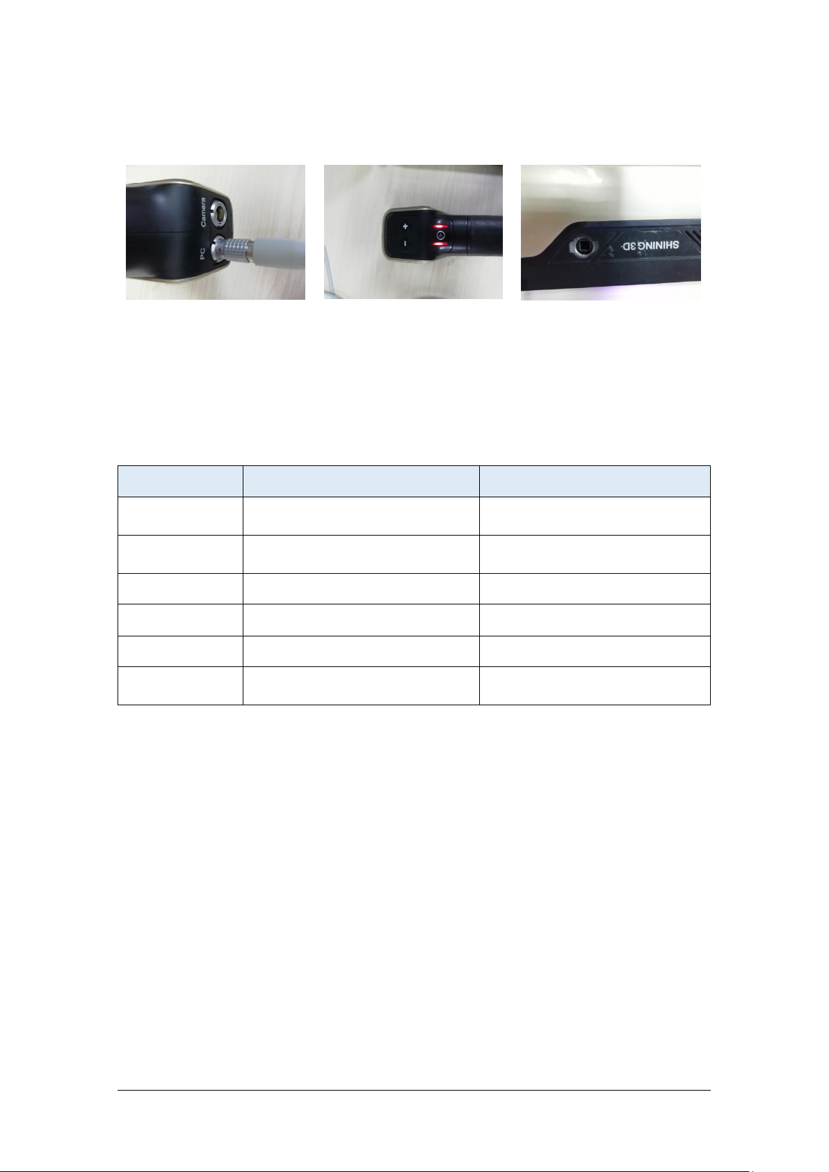
1.3. Hardware introduction
Cable port
+/- buttons
Play button
add-on slot
Model
Required
Recommended
Processor
Intel ® xeon E3-1230, Intel ®I53470, Intel ® I7-3770
I7-8700
Display card
Nvidia Quadro P1000 or higher;
Nvidia GTX660 or higher
NVIDIA GTX1060 or higher
Display memory
>4G
>4G
Memory Storage
8G
32G or more
USB
At least one USB 2.0 or 3.0
2 USB 2.0
Screen display
1920*1080 DPI: 100%; 125%
3840*2106 DPI: 100%; 200%
1920*1080 DPI: 100%; 125%
3840*2106 DPI: 100%; 200%
1.4. PC requirements
Page 10
SHINING 3D - EinScan-Pro series - User Manual - June 2019
10
1.5. Set Up
Hardware set-up
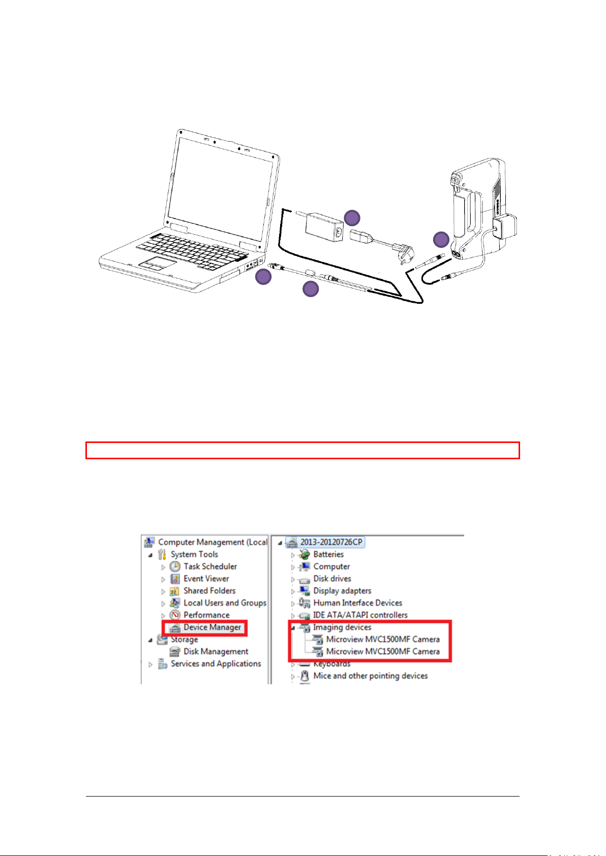
⚠Note: Make sure the cable will stay well plugged in during the operation.
Device Manager, display of the scanner
2 3 4
1
Plug the data cable on the PC port of the scanner (1). The red dot on the cable should
be on up.
Connect the scanner cable to a USB port (2)
Connect the power cable and power adapter. (3-4)
The camera port is intended for the Color camera [see 9.1.2] or the HD prime [see
11.1.2]
After plugged into the computer, check the Device Manager. The scanner should be
displayed like the following picture: under Imaging devices or Cameras, 2 “Microview
MMVC1500MF Camera”
Other cameras should be disable, Right click > disable device.
After the scan, right click > enable device, Windows will run the driver again.
Page 11
SHINING 3D - EinScan-Pro series - User Manual - June 2019
11
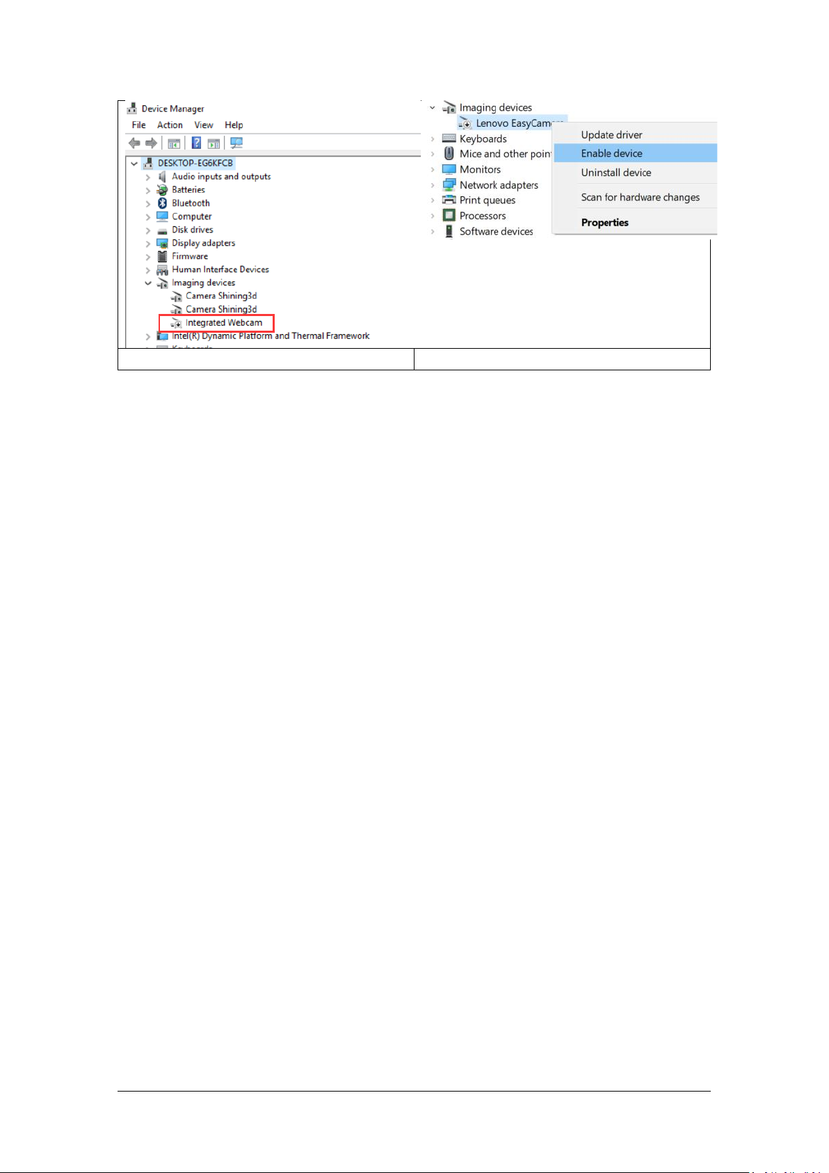
Other camera in the Device Manager
Enable/ disable device on project file
If the drivers are not installed properly, or the Alert “device off-line” keeps coming
back. Right click on the “Microview MVC1500MF Camera” and uninstall the driver.
Unplug and re-plug the USB, Windows will re-install the drivers by itself.
Page 12
SHINING 3D - EinScan-Pro series - User Manual - June 2019
12
2. Software
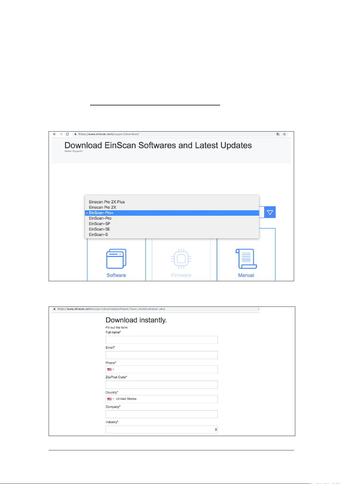
2.1. Download
Step 1: Go to https://www.einscan.com/software-download.
Click “EinScan Software Download” to download the latest version software for
EinScan.
Step 2: Register using the form. All filed with * must be filled in.
Page 13
SHINING 3D - EinScan-Pro series - User Manual - June 2019
13
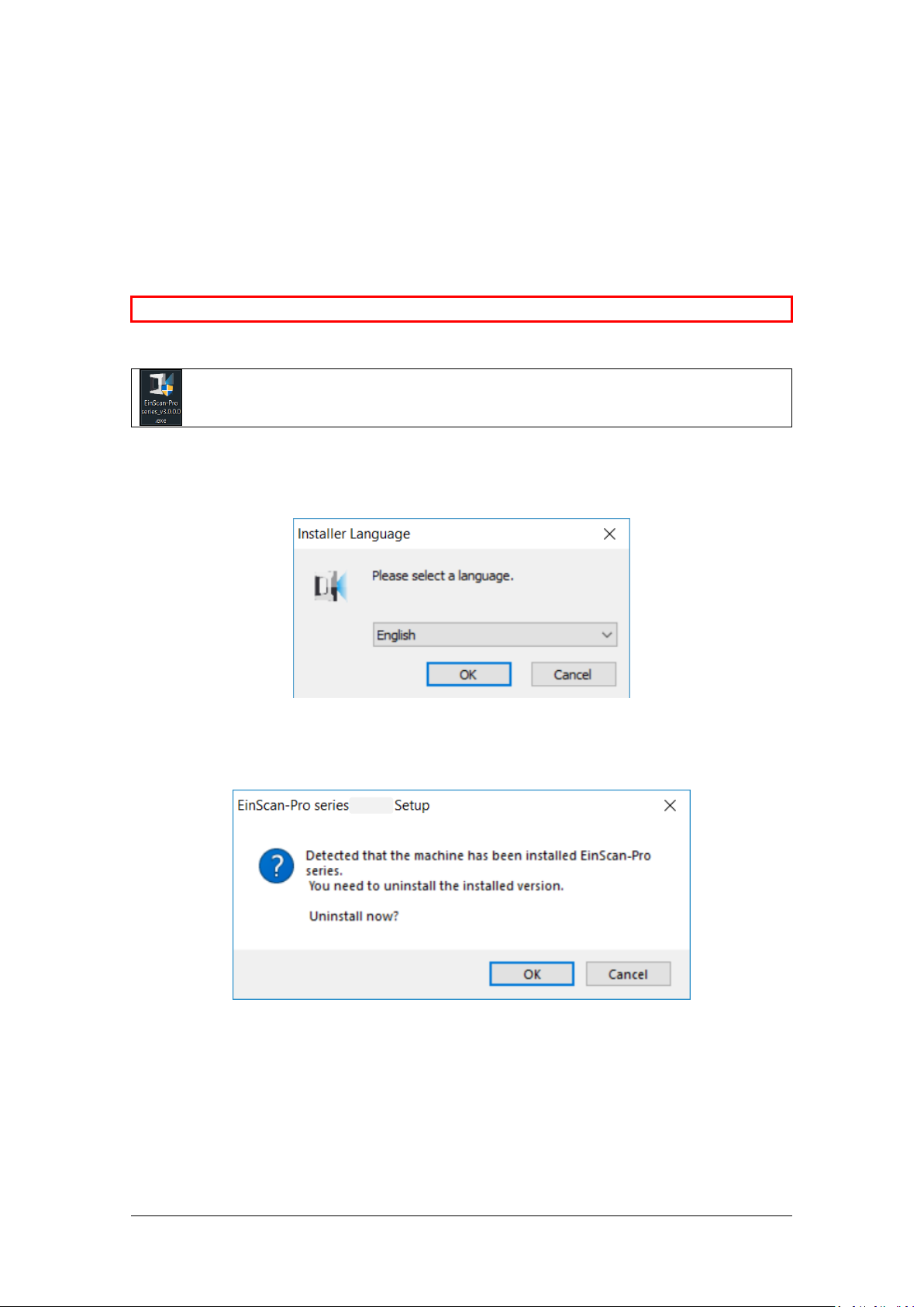
⚠Note: Administrator rights are required for the installation of the software only.
Double click installation package, accept the modification on your computer
Select installation language
Installation conflict
Step 3: Download the installer. Save or Save as in the desired location on your
computer.
2.2. Software installation
Choose the installation language, then click OK.
If a previous version of EinScan-Pro serires software is found it will need to be
unistalled first.
Page 14
SHINING 3D - EinScan-Pro series - User Manual - June 2019
14
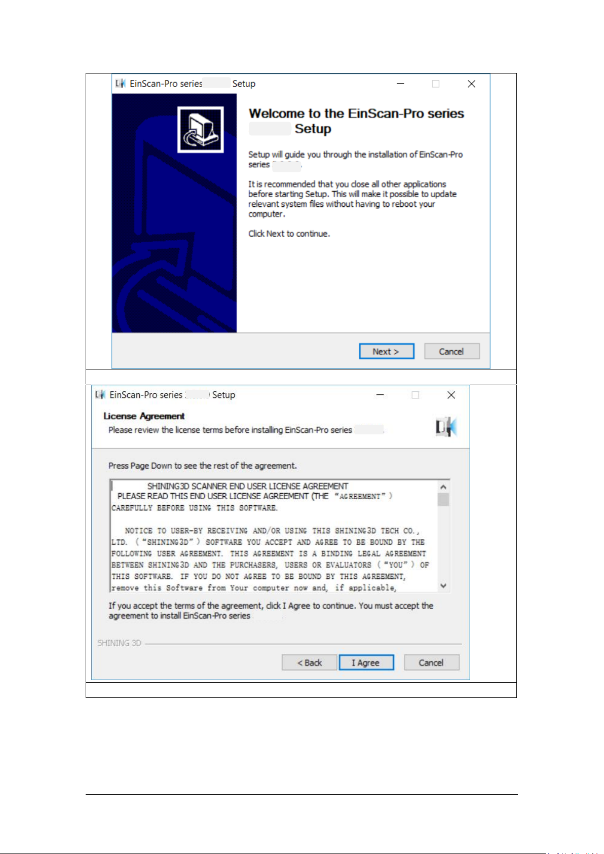
Follow the instruction on the pop-up window
You must accept the agreement to install EXScan Pro.
Page 15
SHINING 3D - EinScan-Pro series - User Manual - June 2019
15
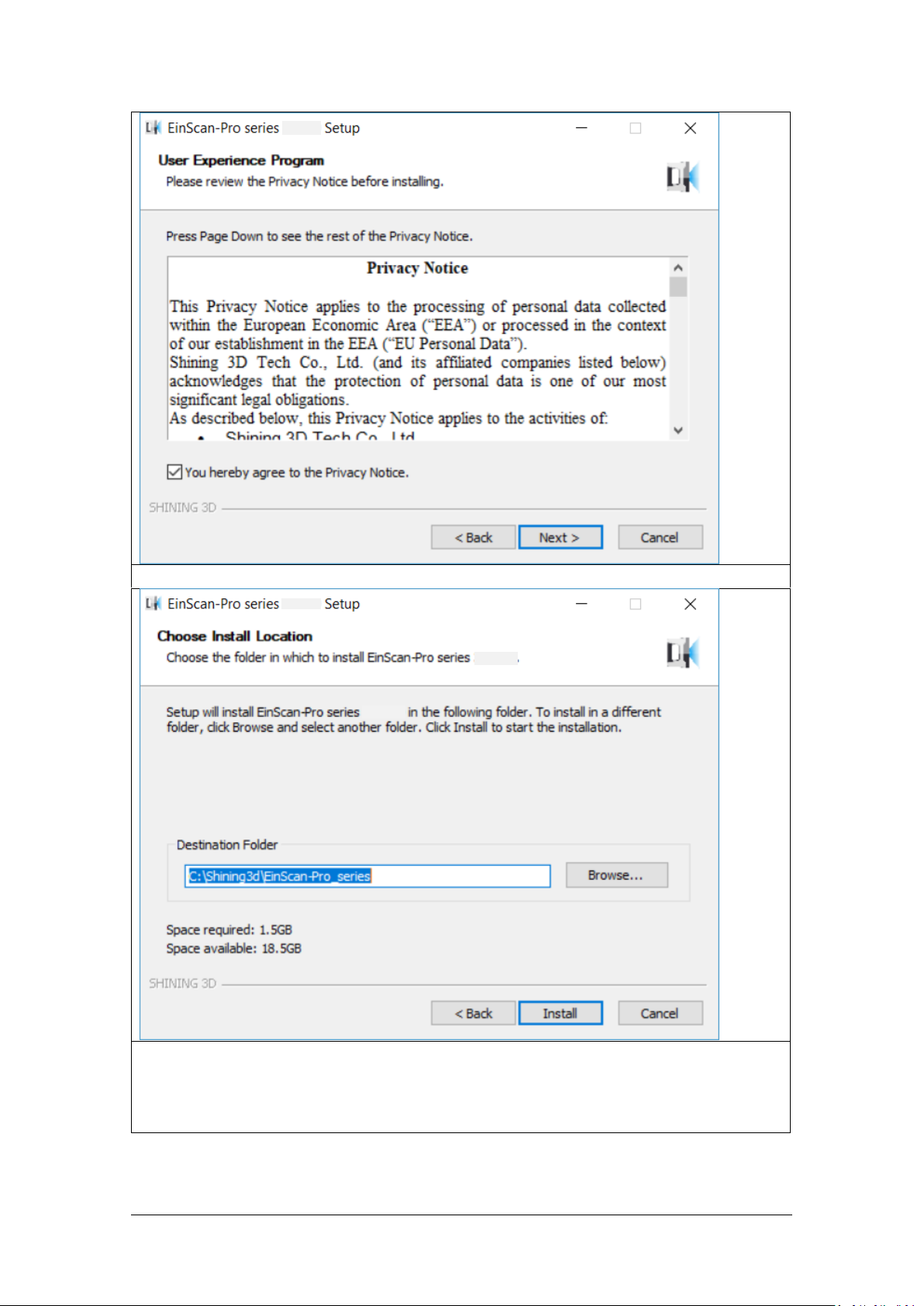
Click the Checkbox and click Next to approve the Privacy Notice
Choose the default installation path or click the Browse button to select the
installation path. Default installation path is recommended.
Page 16
SHINING 3D - EinScan-Pro series - User Manual - June 2019
16
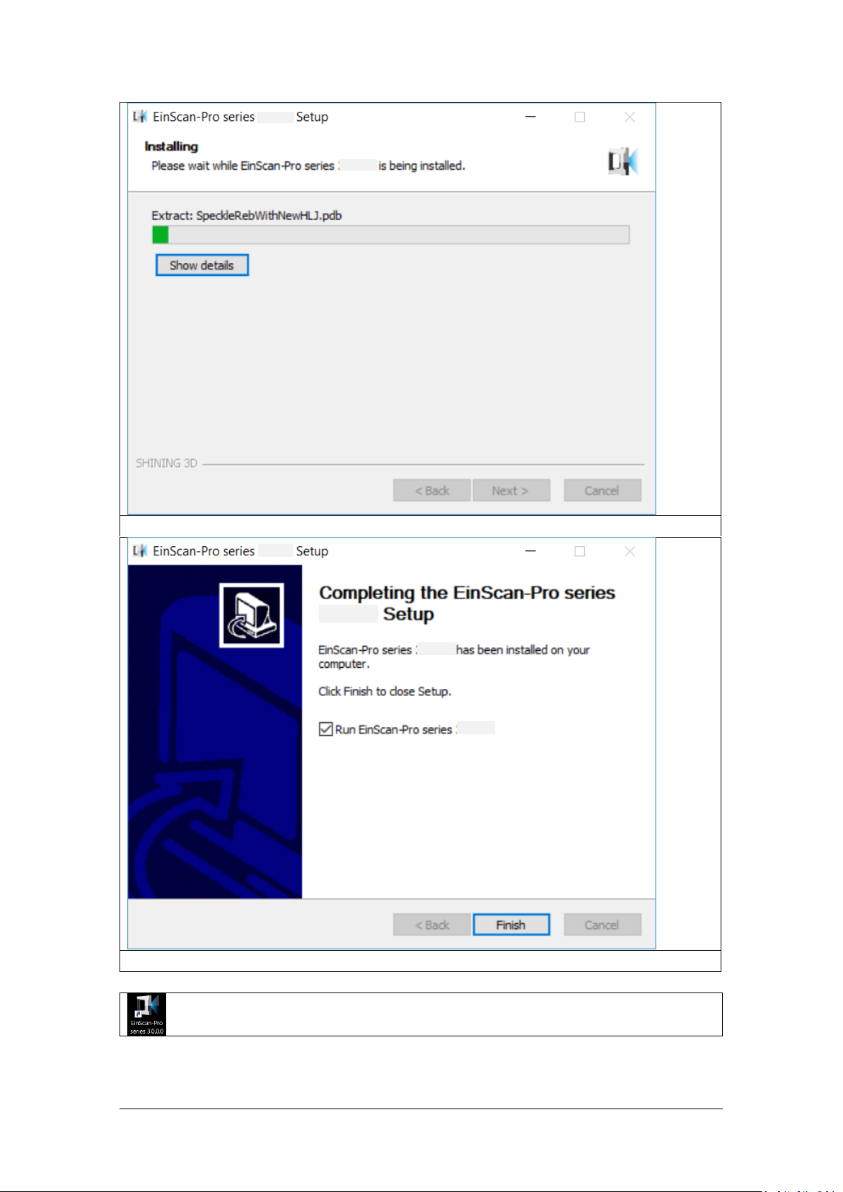
Wait for the installation to be completed
Click the Checkbox and click Finish. The software will start automatically
When the installation is completed, there will be a shortcut Icon of the
software on the desktop.
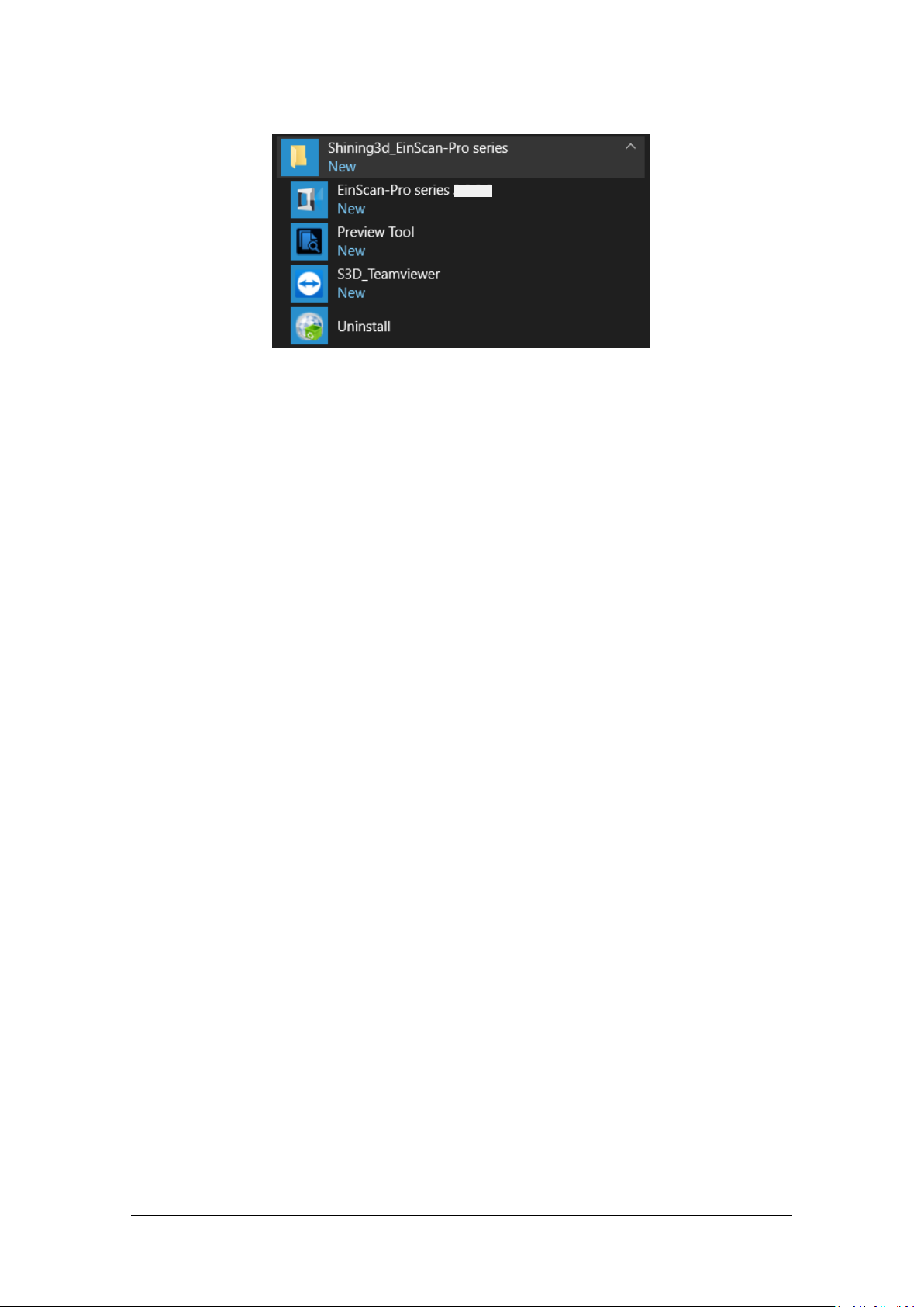
The shortcut in the Start Menu is shown as below:
Page 17
SHINING 3D - EinScan-Pro series - User Manual - June 2019
17
EXScan Pro on the start menu
Page 18
SHINING 3D - EinScan-Pro series - User Manual - June 2019
18
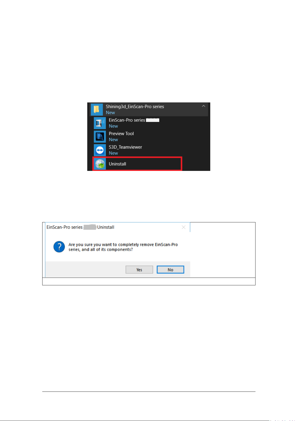
start menu > Shining3d_EinScan-Pro series > Uninstall
Click Yes to uninstall the software
2.3. Uninstall Software
To install upgraded version of EinScan-Pro series in the future, you may need
uninstall previous software first.
To uninstall the software, when the software is closed, in the start menu Click
Uninstall.
Or go to Control Panel > Programs > Program and Features, choose EinScan-Pro
series and right click to uninstall.
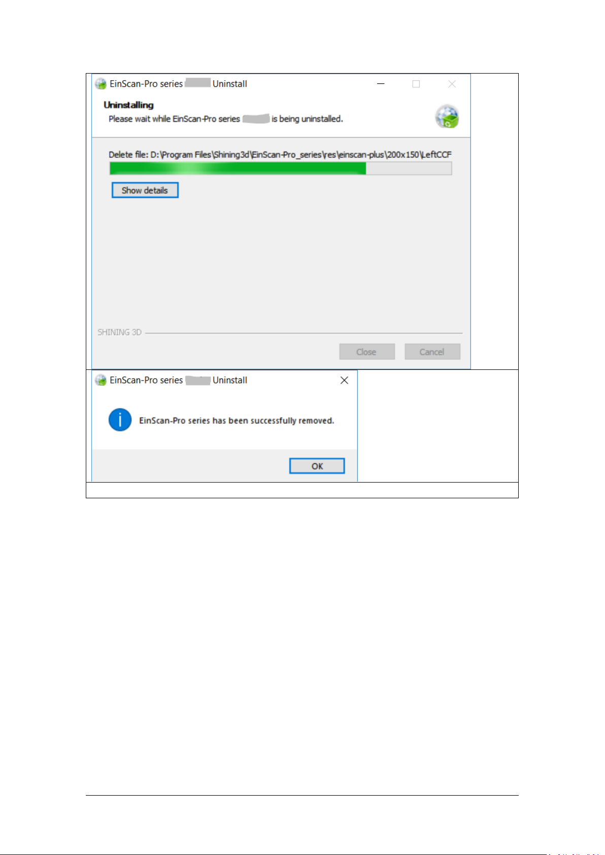
Follow the instructions step by step.
Page 19
SHINING 3D - EinScan-Pro series - User Manual - June 2019
19
Click OK
Then delete the Shining3D folder and its content in (C:).
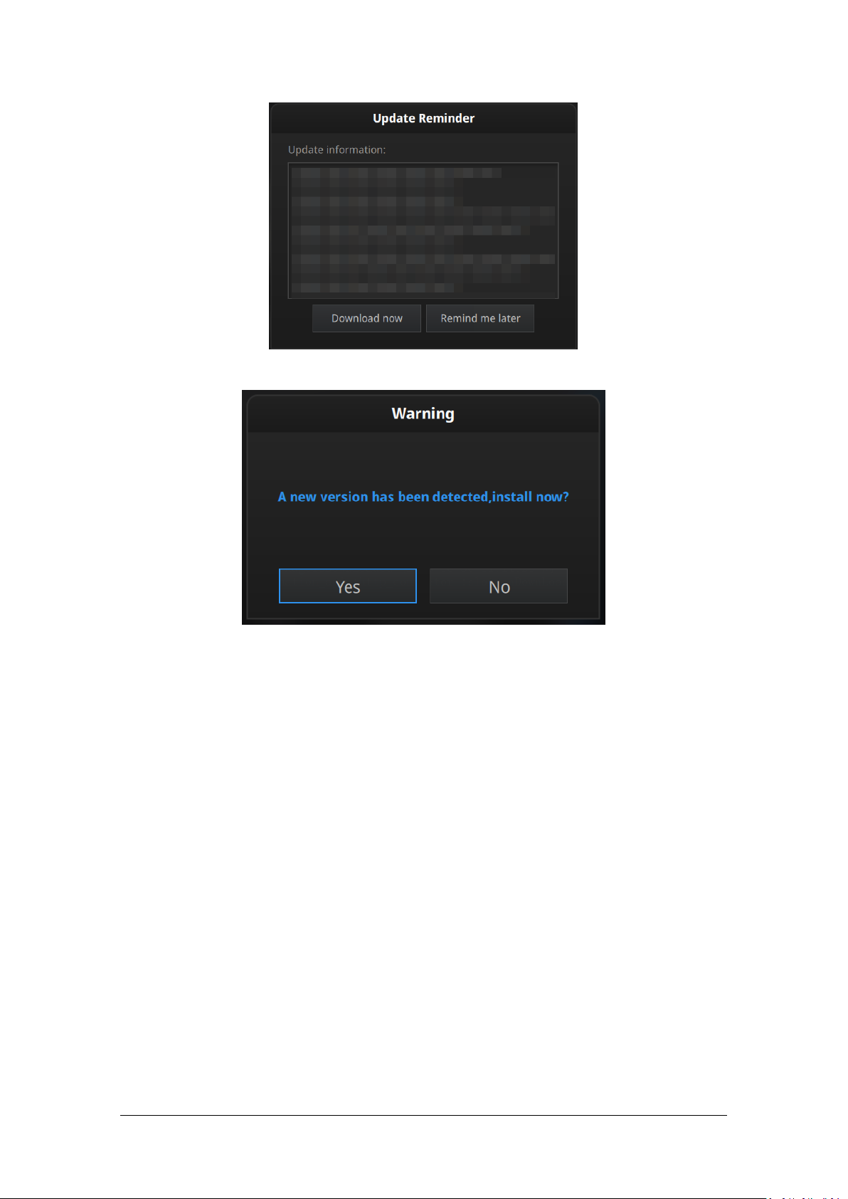
2.4. Update
Make sure to run the latest version of EinScan-Pro series.
If a new version is available, a pop-up will show when you start the software.
Page 20
SHINING 3D - EinScan-Pro series - User Manual - June 2019
20
Update Reminder
Click Yes to update the software version
Page 21
SHINING 3D - EinScan-Pro series - User Manual - June 2019
21
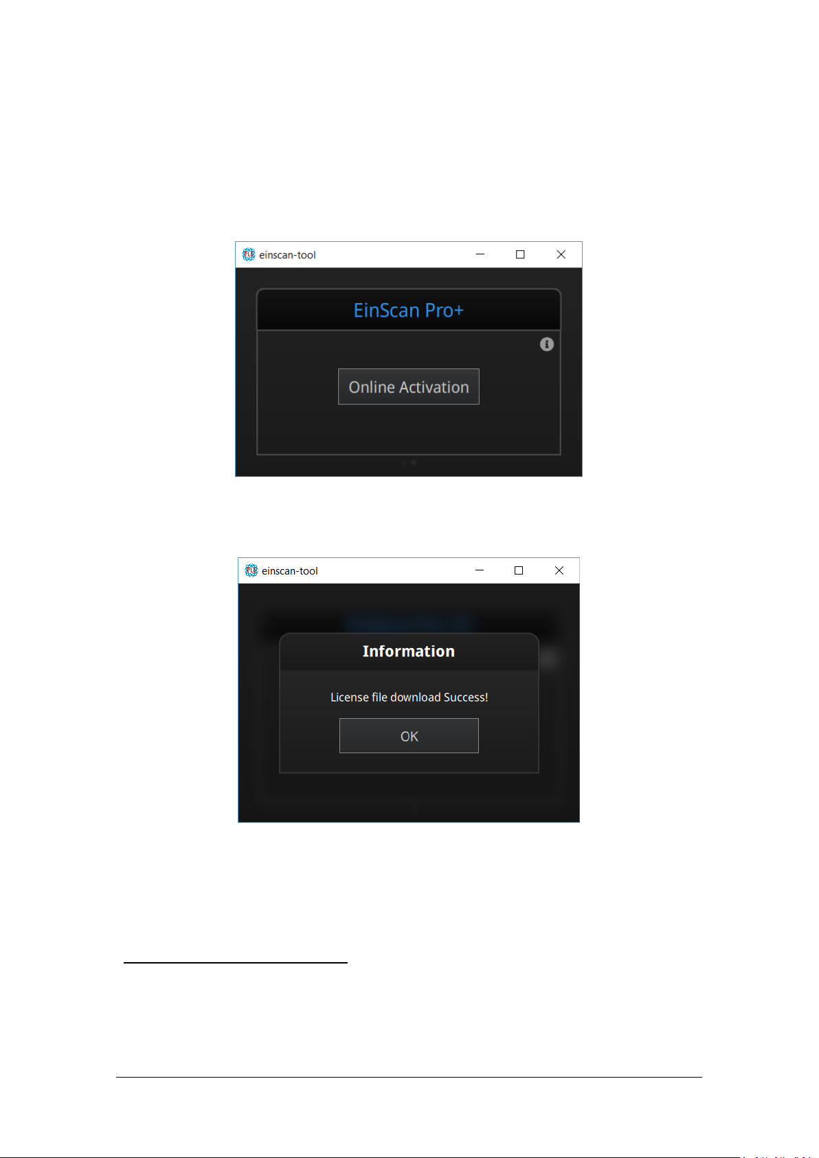
Activation tool
Click OK to continue
2.5. Device activation
When you use the device for the first time, hardware activation will be required.
If your computer is connected to the internet, click “online activation”.
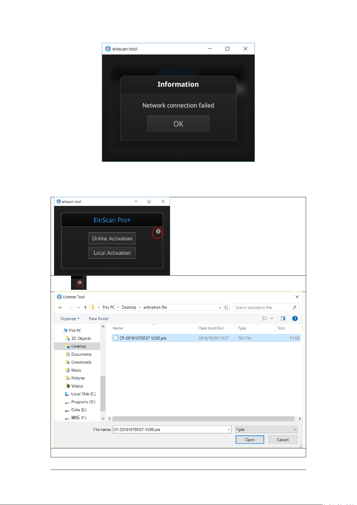
If the computer is not connected to the internet, you can also find the Ple file from
the USB drive.
If the activation fails, send a request for activation file to
einscan_support@shining3d.com and mention your serial number. You can find the
serial number from the sticker on the scanner or label on packing box listing as
“EinscanXXX-XXXXXXXXXX”.
Page 22
SHINING 3D - EinScan-Pro series - User Manual - June 2019
22
Connection failed, check your internet connection or do local activation
click “ ” to reveal the “Local activation” button
Save the .PLE file on your PC, then on the activation menu.
Page 23
SHINING 3D - EinScan-Pro series - User Manual - June 2019
23
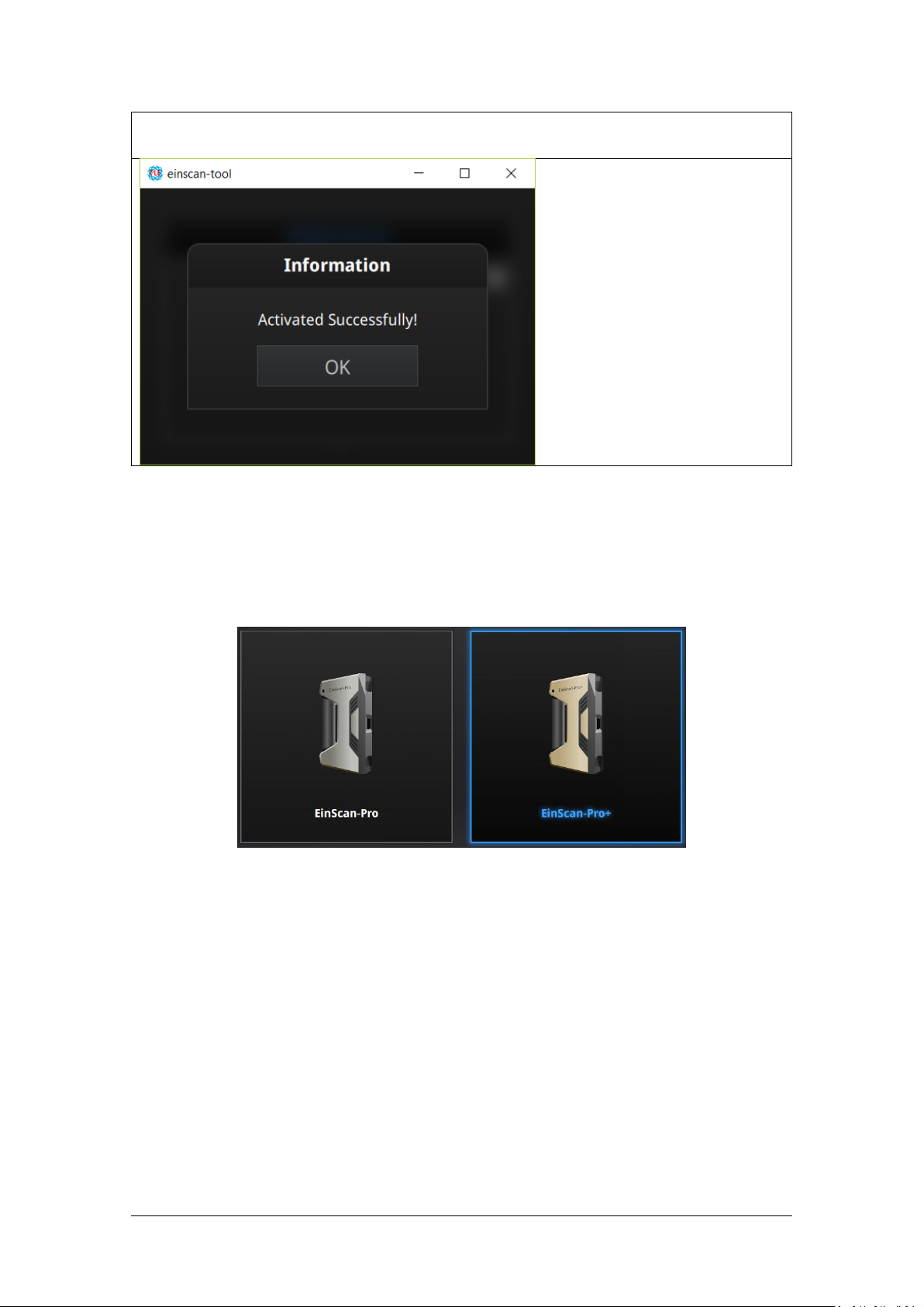
Browse and import the .PLE file.
Selection of scanner type
2.6. Interface and Parameter
At first, after opening the software, click on the icon to choose between Pro and Pro+
Next the scan mode selection will display.
Page 24
SHINING 3D - EinScan-Pro series - User Manual - June 2019
24
2.6.1. Navigate
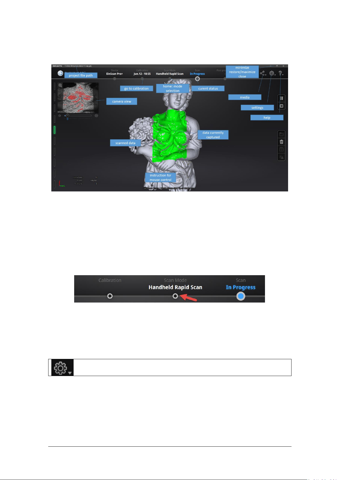
Interface navigation
Navigation bar
Click the settings logo from the upper right to open the drop down menu.
Left mouse: rotate
Middle mouse: move the data
Scroll up and down: zoom in or out
Keyboard:
Spacebar to scan again or restart the scan & validate
Delete key to delete selected data
Esc key to exit current pop-up
Navigate between different menu by click on the circle.
2.6.2. Settings
Page 25
SHINING 3D - EinScan-Pro series - User Manual - June 2019
25
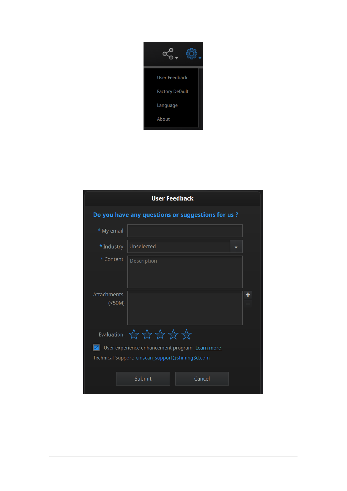
Drop down menu
Feedback window
Feedback
If you have any questions or suggestions, please share with us by clicking “Feedback”.
Please leave your email in “My E-mail”.
User Experience Enhancement Program
To help us improve the quality and user experience of EinScan, we hope to be
allowed to collect usage experience information. This information will not contain
your personal information or scanned data, and will not be accessible to any third
Page 26
SHINING 3D - EinScan-Pro series - User Manual - June 2019
26
party. This checkbox is selected by default, and we strongly recommend you keep it
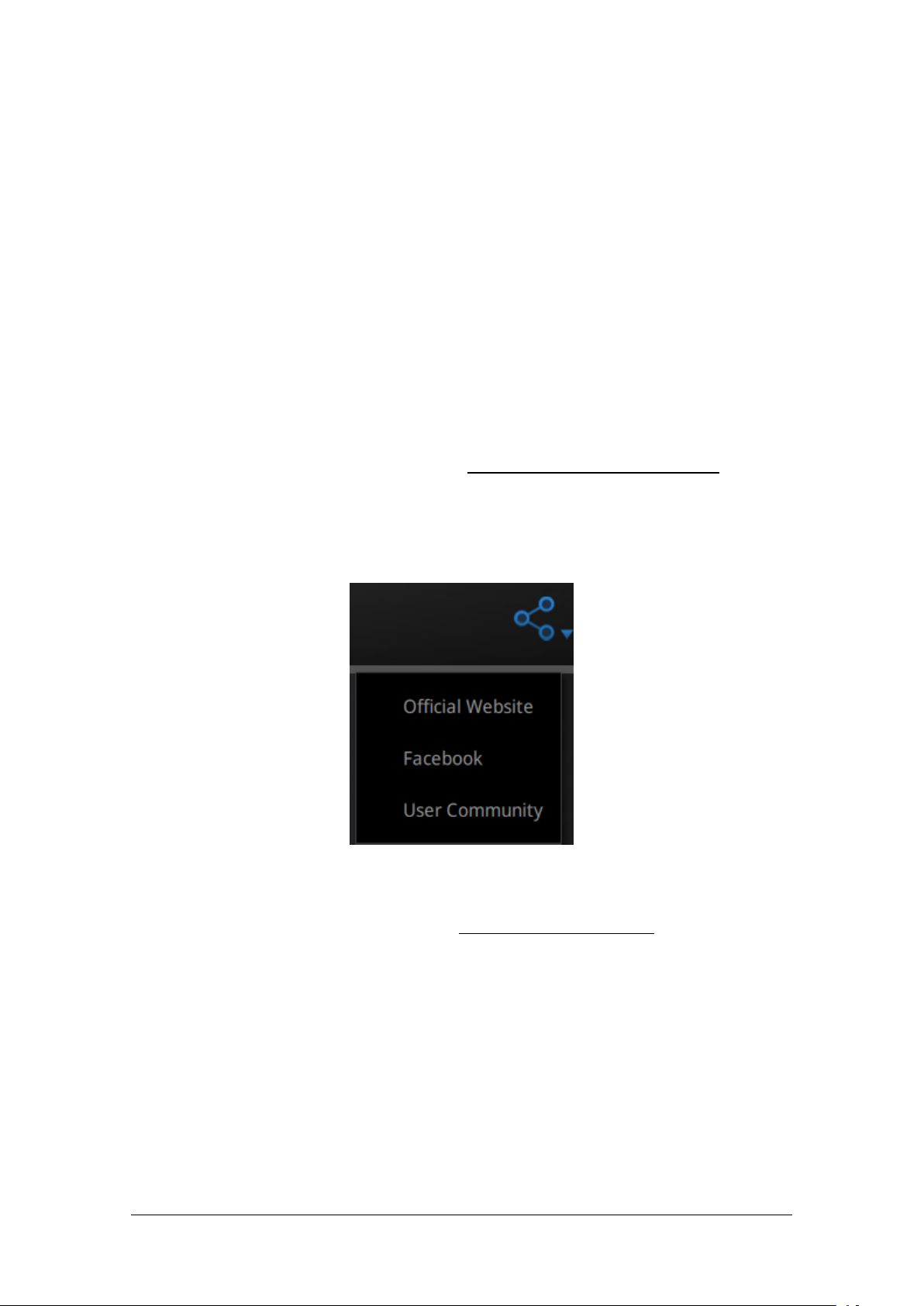
Community drop down menu
checked. As a reward, the User Experience Enhancement Program will continuously
keep you informed with the newest software update information, to assure you get
free software updates and enjoy the latest improvements based on your collective
feedback. If you close the User Experience Enhancement Program, you might not be
informed with software updates automatically.
Factory Default
All settings modifications will go back to the original settings.
Language
Select the language for the interface, click apply to change, restarting the software is
not needed
About
For version information and support, email einscan_support@shining3d.com.
2.6.3. EinScan community
● Official Website
Redirects to SHINING3D’s official website (http://www.einscan.com/) for Einscan
product and information.
● Facebook
Redirects to facebook “EinScan Expert” for EinScan users to discuss and share the
ideas, achievements and experience.
● User Community
Redirects to the platform for EinScan users to validate the warranty and submit
support ticket when necessary. Service live software updates, manual, video
download can be accessed in user community. Register your EinScan at
community.shining3d.com
Page 27
SHINING 3D - EinScan-Pro series - User Manual - June 2019
27
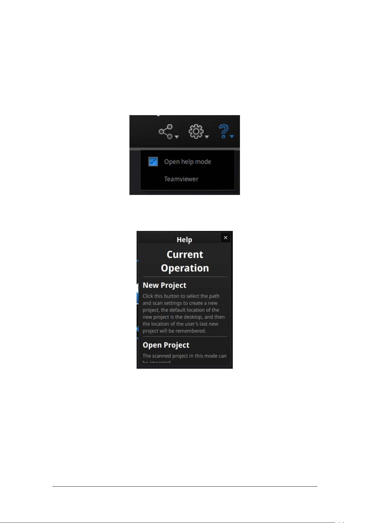
Help window
2.6.4. Help Mode
● Open Help Mode
Click the question mark in the upper right bar, and open the help mode from the
drop-down menu.
Drop down menu
Display the help tool related to the current interface.
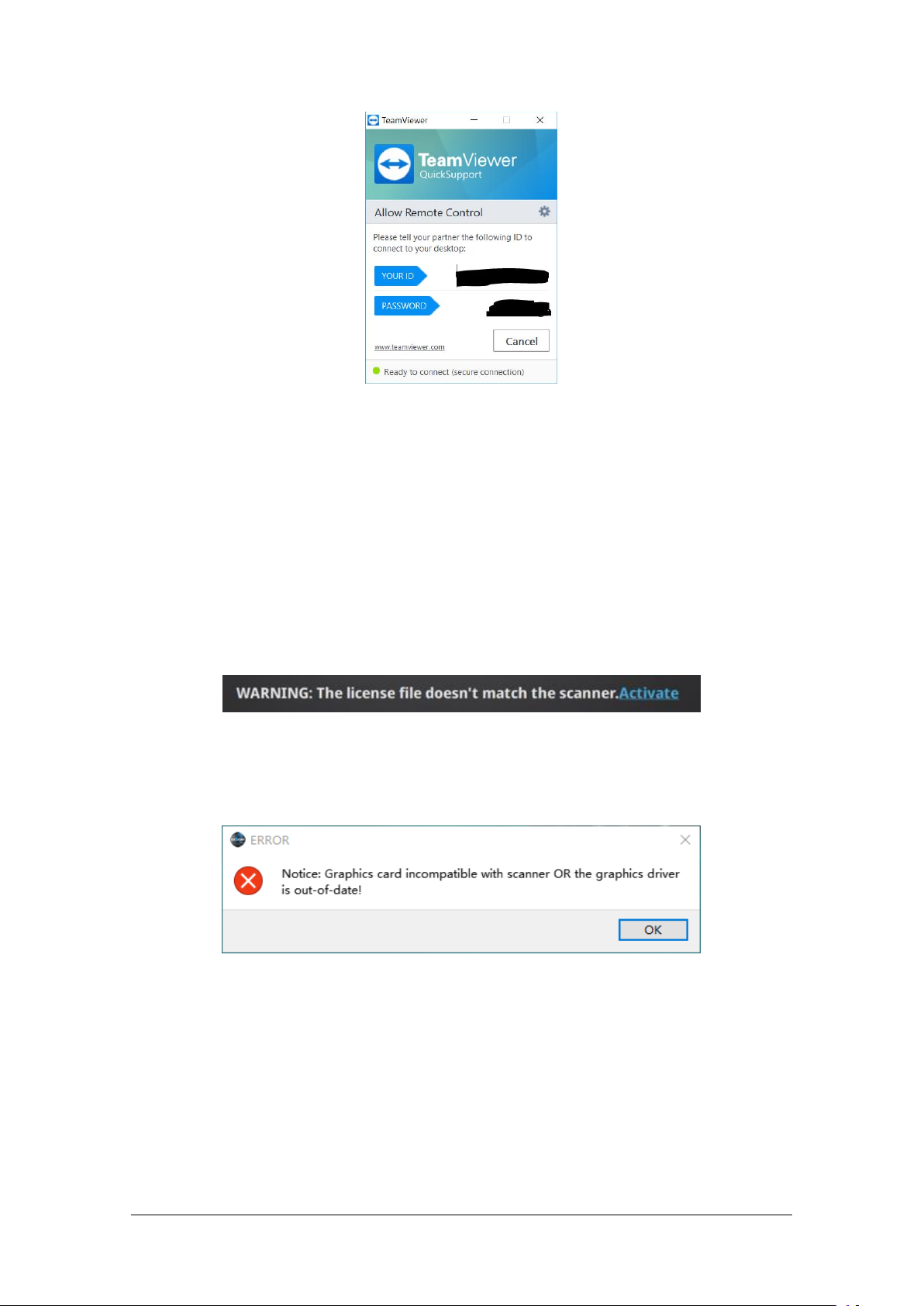
● Teamviewer
It opens S3D_teamviewer.exe, for online customer support access or display to other
screen or portable screen. Share your ID and password to allow our technicians to
remote control of your computer during online technical support
Page 28
SHINING 3D - EinScan-Pro series - User Manual - June 2019
28
Share the Your ID and password to allow access
Device fails to activate
Graphics card incompatible
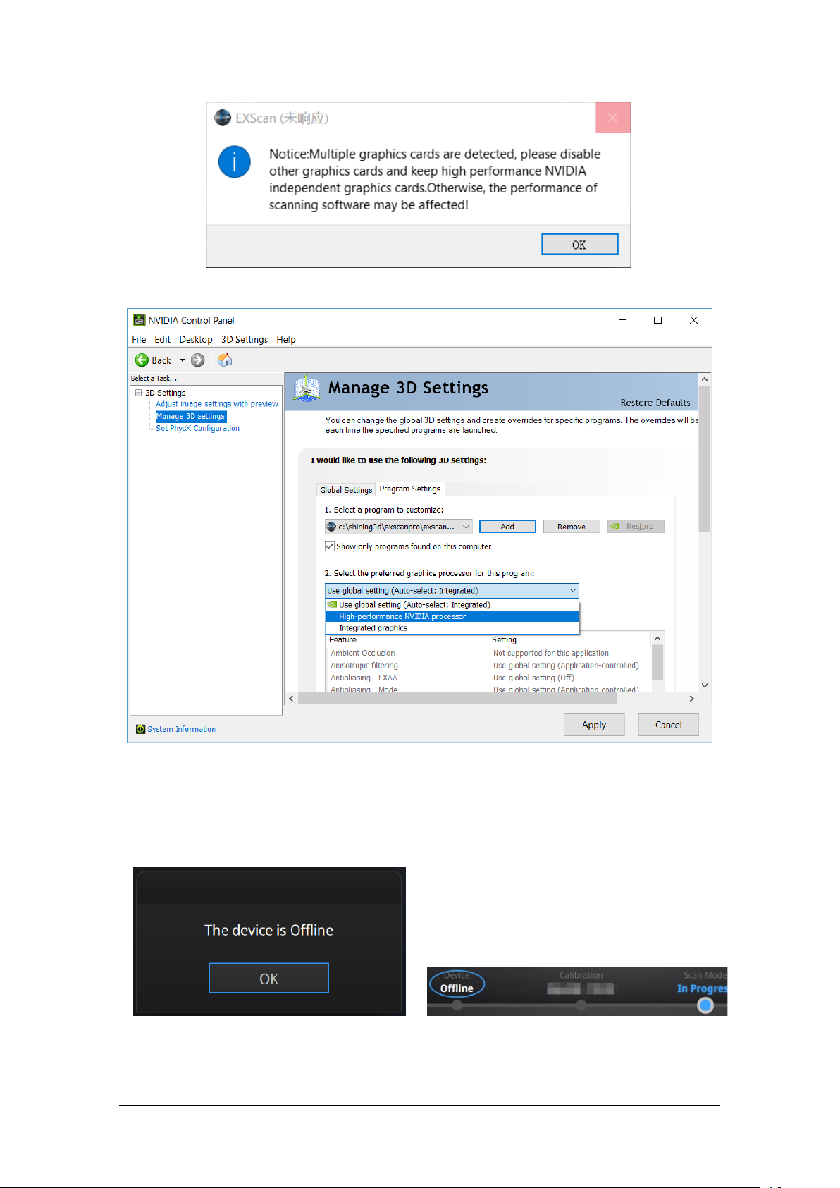
2.6.5. Alerts
A pop-up alert will notify the user of a hardware or configuration issue. Check and
restart the software. If the error persists, please contact support by emailing
einscan_support@shining3d.com.
Fail to activate
For activation failure, make sure the scanner is well connected. Redo the activation.
For incorrect configuration
Try another USB port and update your graphics card drivers and restart the software.
If the computer has multiple graphic card, access to the NVIDIA Control Panel (right
click on the desktop). In Manage 3D Settings > Program Settings, Add EinScan
software. Then change the preferred graphic processor for this program. Select
NVIDIA processor. Click Apply to save the settings.
Page 29
SHINING 3D - EinScan-Pro series - User Manual - June 2019
29
Multiple graphic card detected
Change graphic card preferences for EXScan
Device offline or connection loose
Offline status in navigation bar
Device offline
When the device is offline, meaning the scanner is not connected to PC, please check
the connection and restart the software.
Mode not available
Page 30

SHINING 3D - EinScan-Pro series - User Manual - June 2019
30
Add-on is required for this function
Page 31

SHINING 3D - EinScan-Pro series - User Manual - June 2019
31
3. Calibration
⚠Notes:
Make sure to protect the calibration board and keep it clean, no scratches or
stains on the black surface with white circles.
The Calibration board is matched to the Device with same Serial Number. Doing
the calibration with an incorrect calibration board will fail to generate good scan
data or optimum accuracy.
Clean with clear water only, do not use alcohol or chemical liquid to clean the
calibration board
3.1. Precautions and Use
Calibration is the process to ensure the device will scan with the optimal accuracy
and scan quality. The parameters of the scanner will be recalculated during the
calibration.
Under the following situations, you should calibrate the device:
◆ Device change
◆ After device enduring bumpy transportation
◆ After device accuracy decreases
◆ The device has not been calibrated for 15 days or more
◆ After device plugged in with color camera
3.2. Operation
After installation, when you open the software for the first time the software will
enter the calibration mode by default. You can also choose Calibration on the
navigation bar to enter calibration process later.
Page 32

SHINING 3D - EinScan-Pro series - User Manual - June 2019
32
Calibration interface
3.2.1. Camera Calibration
Scan on the front side of the board (black surface with white circles) for calibration.
Follow the instructions video on the screen to capture the 5 different steps. The
calibration board needs to be placed in five positions of different heights during
calibration, each captures five pictures. Place the board according to the software
guide.
Step 1, place the calibration board flat in accordance with the direction in the
picture, keep the cross pattern projected by the scanner in the white frame on the
calibration board.
Then lift the scanner to change the distance between the projector and calibration
board according to the software guide.
Page 33

SHINING 3D - EinScan-Pro series - User Manual - June 2019
33
On-screen instruction during calibration step 1
Click Start in the software or press Play button on the scanner to
capture automatically
or play button
⚠Notes:
When the distance bar is ticked, it means pictures of this position are collected.
Blue means the current position.
Keep the cross in the white square area when moving the scanner
During calibration, keep the scanner vertical, not parallel to the calibration
board.
Do not move the board during the capture
During the capture process, LED rings blink and a cross is projected. Move the
scanner from top to bottom or from bottom to top slowly and steadily, until every
step in the rangefinder is green, which means the first capture is complete. The
software will play a beep sign. During capture, lift the scanner up when software
shows “too close”; move the scanner down when software shows “too far”.
When pictures of one position are well collected, the software will turn to the next
position with buzzer as below:
Page 34

SHINING 3D - EinScan-Pro series - User Manual - June 2019
34
Calibration step 2
Calibration board on its support for step 2
Place the calibration board on the support according to the instruction. The
collection is the same as above. When all five positions photos are captured, the
software will calibrate the camera automatically. You will see the result as below.
Calibration will take longer or fail if you did not follow all instructions properly. When
calibration succeeds, click “Next” to move on to the HD calibration or white balance
as the software indicates. Or it will go back to the scan mode selection interface if
there is no other calibration required.
Page 35

SHINING 3D - EinScan-Pro series - User Manual - June 2019
35
Camera calibration result
If calibration fails, click “Redo calibration” to start the same calibration again from
the beginning.
Calibration failed
Click “Next” to perform HD calibration or white balance as the software indicates. Or
it will go back to the scan mode selection interface if there is no other calibration
required.
3.2.2. HD Calibration (Only required for EinScan Pro)
On the back side of the calibration board (white) follow the instructions on the video
and on the screen to capture the different position. The software will then calculate.
Page 36

SHINING 3D - EinScan-Pro series - User Manual - June 2019
36
HD calibration result
Click Start in the software or press Play button on the
scanner to capture automatically
or press
Go back to the scan mode selection page by clicking “Next” at the bottom left.
3.2.3. Accuracy test
While scanning, if markers cannot be recognized, tracking is easily lost or
misalignment happens often, Accuracy Diagnostic is suggested.
Same as camera calibration step1, scan on the front side of the calibration board
(black) to do an accuracy test.
During the capture process, LED rings blink and a cross is projected. Move the
scanner from top to bottom or from bottom to top slowly and steadily, until the
rangefinder is completely filled with green bars.
Follow the instructions on the video and on the screen to capture the different
pictures.
Page 37

SHINING 3D - EinScan-Pro series - User Manual - June 2019
37
Accuracy error result
How it works: The software calculates point position and compare it to the known
value. The deviation is display as result
If the result is more than 0.1 mm (accuracy for handheld mode), redo the calibration,
and test again.
Go back to scan mode selection page by clicking “Next”.
4. Before Scan
4.1. Object
EinScan Pro series can scan objects from 30*30*30mm ^3 to 4m length.
We do not recommend scanning:
Page 38

SHINING 3D - EinScan-Pro series - User Manual - June 2019
38
● moving or vibrating objects, which cause the shape of object changed during
Example of an object, difficult to scan
The pure black letters are
hard to be captured by
the scanner.
The silver bottom is highly
reflective, so it also hard
to be seen by the scanner.
The can is
symmetrical and
has no geometry
features on the
surface. It is
difficult for the
software to align
the scanned data.
scanning process.
● lattice structures with many small deep holes
During scanning the shape of the object needs to be maintained without any changes
(human bodies must be held still, for example).
4.2. Preparation
To align data if geometry features are not sufficient, you need to stick markers or
pieces of clay on the surface of scanned objects to create extra “features”.
When you stick markers on the surface of the object, you need to follow the
following rules:
(1) Make sure sticking at least 4 markers in each frame (one scanning field of view).
Control the number of markers seen on the camera view.
(2) Stick markers in a random, non-linear pattern (see example below).
(3) Markers should be stuck on the flat surface area and keep the marker surface
flat.
(4) Use the markers provided with the device only. Other markers can result bad
accuracy or not to be seen.
Page 39

SHINING 3D - EinScan-Pro series - User Manual - June 2019
39
Object with markers
Markers surrounding the object
If the object is small enough for each frame (scanning field of view), markers can be
placed around the object. Make sure the object will not move from its support
during the scan, which means the position relationship between the object and
markers should not be changed.
Before scanning transparent, highly reflective and black objects, you should spray
white powder on the surface (see example above).
Page 40

SHINING 3D - EinScan-Pro series - User Manual - June 2019
40
4.3. Select Scan Mode
Mode
Accuracy
Speed
Resolution
Align mode
Fixed scan
With turntable
(industrial pack)
****
****
*****
Turntable coded target,
features, Markers, manual
Fixed scan
No turntable
****
*
*****
Markers, features, manual
Handheld HD
scan
*** * ***
Markers
Handheld Rapid
scan
*
**
**
Features
R2 : markers, hybrid
Mode
Accuracy
Speed
Resolution
Align mode
Fixed scan
With turntable
(industrial pack)
****
****
****
Turntable coded target,
features. markers, manual
Fixed scan
No turntable
****
*
****
Markers, features,
manual
Handheld HD
scan
***
***
***
Markers
HD prime pack : features
Handheld Rapid
scan
*
****
**
Features,
markers, hybrid
Chart to choose scan mode with Pro
Chart to choose scan mode with Pro+
The tables above show the details of each scan mode that can be selected. For
limitations of each scan mode, refer to the specifications presented previously.
Page 41

SHINING 3D - EinScan-Pro series - User Manual - June 2019
41
4.4. Scan Workflow
Page 42

SHINING 3D - EinScan-Pro series - User Manual - June 2019
42
5. Fixed Mode (Industrial Pack Required)
Create a project, fixed scan
Fixed Scan Mode is designed for achieving high resolution and high accuracy
scanning for small (from 30*30*30 mm^3) to medium size objects.
In this mode, the scanner and the object are fixed during a single scan. The relative
position between the scanner and the object can be changed to capture different
area of the object on separated single scans. Successive single scans are aligned
automatically or manually based on the common area or markers to generate a
whole scanned data.
The add-on “Industrial Pack” is dedicated to this mode, with a tripod and a turntable
Perfect for object fitting on a Φ 150mm disc.
Tips: The objects’ footprint can be bigger than 150mm in Fixed Scan with Turntable if
you do not need to use codes on the turntable for auto alignment. You can instead
use geometry features or markers on the object’s surface for automatic alignment, or
use manual alignment mode to get the whole scanned data.
The texture camera (Color Pack add-on) can be used in this mode.
5.1. Set Up
5.1.1. Create a Project
Enter the interface of New Project and Open Project. The initial default project save
location is on the desktop unless the user opts to change this. Click “New Project”,
enter the project name, then click ‘Save’ to enter the scan parameters window.
Texture scan is only active when the texture camera (Color Pack) is attached to the
scanner.
Page 43

SHINING 3D - EinScan-Pro series - User Manual - June 2019
43
In the new project interface, you have the option to click browse to import a Global
Browse to load a GMF
⚠Notes:
GMF file is suggested for scanning large size object with high accuracy.
When using the global markers file, new markers cannot be scanned. Global
markers points can be deleted.
Pro
Pro+
Closer limit (mm)
300
400
Optimal distance (mm)
400
500
Upper limit (mm)
400
600
Set up for fixed mode
⚠Note: The tripod is NOT included in the Standard Pack, but it is included in Industrial
Pack together with a turntable.
Marker File (GMF) as .ASC, .TCT or .P3. Global Marker File is normally captured by a
Photogrammetry System to achieve a high accuracy Markers Frame for large object,
in which you can scan the object in detail and match the global accuracy of Markers
Frame.
5.1.2. Working Distance
Adjust the distance between the object and device. Make sure the scanner will not
move during the scanning.
At the proper working distance, the cross should be seen clearly with a sharp contour
on the surface.
Page 44

SHINING 3D - EinScan-Pro series - User Manual - June 2019
44
5.1.3. Interface
Scan interface, Fixed mode
⚠Note: Right Click on the camera preview to display the Right camera in the window.
You will see the parts shown in the window from right camera. The parts which can be
seen by both cameras will be captured. Adjust the position and orientation of the
scanner or the object accordingly to finish the scan from different direction.
Drag to adjust the brightness setting
Turn HDR ON to scan contrasting textures
5.1.4. Adjust Brightness
Click and drag the button to adjust the brightness. The correct brightness setting will
depend on the lighting in the environment and the texture of the object.
To scan an object with high contrasting texture, such as something white and black,
select HDR. Each single scan will take longer to capture.
Page 45

SHINING 3D - EinScan-Pro series - User Manual - June 2019
45
5.2. Scan with Fixed Mode
Click the button or press space bar to start scanning
Click the pause button, and the scanning will pause; Click again to resume
scanning.
Edit buttons:
①Deselect
②Revert
③Delete
④Undo
⑤Show/Hide texture (for data with color texture only)
⑥Shift + Left mouse: choose data
⑦Ctrl + Left mouse: deselect selected data
5.2.1. Capture
When the scan is completed the data is automatically saved in the project file.
5.2.2. Edit Scan
After the single scan is completed you can edit the data.
SHIFT + Left mouse: Select unwanted points, the selected points will turn red
Ctrl + Left mouse: Deselect selected data.
Page 46

SHINING 3D - EinScan-Pro series - User Manual - June 2019
46
Delete selected data
Click the button or the “Delete” on the keyboard to delete selected data.
Undo
You can only undo the most recent deleted data.
Show/Hide Stripes (for data with color texture only)
Click the button to switch the texture option between display and hide.
Press the space bar on the keyboard to save data and exit the single-scan
editing. The edited data is saved in the project file
Cancel editions on the data
click the button to delete current data
If you are not satisfied with current scanning data, or there is not enough
overlapping regions or markers between neighboring scans for registration,
Then change the position of the scanner or the object to scan again.
Page 47

SHINING 3D - EinScan-Pro series - User Manual - June 2019
47
5.3. Scans & Groups
Scans & Groups tab
Create a group with the selected scans and/or group(s)
Click the button to delete the selected scan(s) and/or group(s)
Scan or group visible / invisible
⚠Notes:
By default, the scanned data in one rotation of turntable (industrial pack) belong
to one group. The group can be deleted or split to realign with other group data
or single data.
Disable texture (color pack) to select scan by left mouse on the 3d view
5.3.1. Create Groups
Left mouse: Select scan/group on the scan list or on the 3d view
SHIFT/Ctrl + Left mouse: Select multiple scans/groups
A new group will be generated by all selected scans. (sub-group cannot be created)
Right click on the selected scan/group to access more options on drop down menu.
Page 48

SHINING 3D - EinScan-Pro series - User Manual - June 2019
48
5.3.2. Edit scan(s)/group(s)
Click the button to open the Manual Alignment interface
Drag and drop single scan or group to the float and fixed window
click the button to remove the scan/group from fixed or float window
Texture visible ON/OFF (color pack only)
Double click on a group or a scan, to enter the edition mode. The edition are applied
to the selected data only. Modifications will not affect the rest of the data.
Shift + left mouse: select data on the 3d view, and enter the edition mode. the
edition is applied on the visible data only.
See [5.2.2.Edit Scan] for the edition functions.
5.4. Alignment
If you use markers, the data will automatically align with the marker positions. If not,
an automatic alignment will be calculated with a best-fit of the single scan to the
previous scans according to the geometric features. If the object is not with enough
geometric features, you can use manual alignment.
Single scan or group can be dropped into both windows. Scans in the group are not
allowed. Split the group first if it is needed.
SHIFT + click left mouse button to select at least 3 non-collinear corresponding
points in the 3D preview windows for Manual Alignment, as shown below.
Ctrl+Z: cancel last point picked
Page 49

SHINING 3D - EinScan-Pro series - User Manual - June 2019
49
Select 3 points to align the data
How it works: The software calculates the best fit alignment from the picked points,
and refine the alignment by best fit of all the points of the floating to the points of
the fixed.
Click Confirm to validate the modification and go back to the scan interface
Click Reset to go back to the scan interface
Click Next to continue to align scans
Page 50

SHINING 3D - EinScan-Pro series - User Manual - June 2019
50
6. HD Mode
⚠Note: The texture can’t be captured when scanning in HD mode or HD Prime.
HD mode means the hand-held scan mode with high resolution and high accuracy.
When the operator holds the scanner in hand and moves around the object, the data
is instantaneously captured and matched with previously captured data.
HD mode uses markers to align the data during the scanning process.
Prime (HD Prime pack add-on) can be used in this mode if your device is EinScan
Pro+. It improves a faster scanning speed and enables the feature alignment
(Markers-free) for scanning objects with enough geometry.
6.1. Handheld Scanner Key Function
6.2. Before Scan
Enter the interface of New Project or Open Project. The default project is saved to
the desktop. You can change the saving path, and then the newly created project will
be saved to the new location. Click “New Project”, input the project name, then click
‘Save’ to enter the scan parameters window. Feature alignment is only active when
the HD Prime pack is attached and the scanned object has enough geometric
features. It is only applicable to the EinScan Pro+.
Page 51

SHINING 3D - EinScan-Pro series - User Manual - June 2019
51
Project interface
HD mode scan parameters window
Resolution
Select a resolution for the project. The higher the resolution, the better the details,
but this may lead to larger files and processing times. Choose High (0.2mm), Medium
(0.5mm) or Low (1.0mm) or drag the cursor to choose another point-distance setting
from 0.2mm to 3.0mm.
Global Marker File
If you want to use a previously created Global Marker File (GMF), you may click
browse to import one as .ASC, .TCT or .P3.
Page 52

SHINING 3D - EinScan-Pro series - User Manual - June 2019
52
Browse to load a GMF
Page 53

SHINING 3D - EinScan-Pro series - User Manual - June 2019
53
6.3. Scan
Start Preview mode
or press
Preview mode on HD mode for Pro+
Exit Preview mode and start the scan
or press
6.3.1. Preview
Hold the scanner to face the object (there must be enough markers on the surface),
press the Play button or click Preview to run into Preview mode. In this mode, it will
start to show data for preview, but not record this data.
In this mode, you can:
● Check the working distance
● Adjust the brightness sensitivity
● Ensure that the markers are well captured.
Page 54

SHINING 3D - EinScan-Pro series - User Manual - June 2019
54
⚠Notes:
Preview mode will start every time a new project is built or an existing project is
imported.
After exiting preview and starting the scan, the preview mode will not be shown
again in this scanning project.
To access preview mode on a current project, reopen it.
Pro
Pro+
Closer limit (mm)
300
450
Optimal distance (mm)
400
500
Upper limit (mm)
400
550
Click Start in software or press the Play button to exit the preview mode and start the
scan
6.3.2. Scan Distance
The rangefinder on the left side reveals different colors based on the distance
between the scanner and the object. At the correct distance, it will show green. It
shows red if the distance is too close or blue when the distance is too far.
On the scanner, the information is displayed on the colored LED. As with the
rangefinder on the screen, if it is too close it will show red and if it is too far it will
show blue, and green is perfect.
Adjust the scanner position until the range finder’s color turns green.
Page 55

SHINING 3D - EinScan-Pro series - User Manual - June 2019
55
Too Close
Good
Too Far
Double-
press
Enter/Exit the exposure adjustment menu
Exposure adjustment menu, press +/- or click and drag the cursor
6.3.3. Brightness
When scanning or in Preview mode, double-click the Play button to adjust the
brightness by pressing “+” or “-”buttons on the scanner, or click and drag the cursor
under the camera preview to the left (-) or right (+).
Adjust the brightness according to the following illustration: Red means overexposed,
black is underexposed, and white or light grey is good.
Page 56

SHINING 3D - EinScan-Pro series - User Manual - June 2019
56
The lines and the markers should be seen clearly, the lowest brightness where this is
Too bright ❌
Good ✔
Too dark ✔
Start/Restart scan
OR press
possible is optimal. An overexposed scan will capture more noise.
Double-click the Play button to exit the brightness adjustment window.
6.3.4. Start Scan
Press the Play button or click Start in software to start scanning and recording data.
100 lines are projected with Pro+, while 7 lines are projected with Pro.
During scanning make sure to keep the scanner perpendicular to the surface, keep a
proper distance from the object, and adjust the brightness depending on the
ambient light and texture of the object.
Page 57

SHINING 3D - EinScan-Pro series - User Manual - June 2019
57
Scan interface, HD mode
Enter pause menu
OR press
Press the Play button or click Pause in the software to pause the scan.
6.3.5. Alignment
The software will recognize the markers (displayed in red), record data and align with
previously collected markers (displayed in green). The data is captured along the
lines, as shown below.
To record the data, a minimum of 4 markers (displayed in red) in each frame (every
scanning field of view) has to be captured.
Page 58

SHINING 3D - EinScan-Pro series - User Manual - June 2019
58
Interface with markers
Track lost alert
⚠Note: If you have imported a global marker file, new markers cannot be added
during the scan
Enter pause menu
or press
Stick markers on the object in a random pattern, avoiding sticking all markers in one
line. To check the rules of sticking markers, please refer to section 4.2, Preparation.
If the position tracking fails, the “Track lost” alert will appear, and you will need to go
back to an area with previously recorded markers to recover the tracking again and
continue scanning.
6.4. Pause Menu
In offline mode, the data can be loaded at this step for editing.
6.4.1. Auto Save
Page 59

SHINING 3D - EinScan-Pro series - User Manual - June 2019
59
Continue scan
or press
Generate point cloud
Edit buttons:
①Deselect
②Revert
③Delete
④Undo
⑤Show/Hide texture (color pack only)
⑥Shift + Left mouse: choose data
⑦Ctrl + Left mouse: deselect selected data
Delete selected data
Click the button or “DELETE” on the keyboard to delete the selected data.
Undo
You can only undo the most recently deleted data.
⚠Note: Handheld scan mode does not support the deletion of markers.
End the editing
Press the Play button or click Pause in the software to enter the Pause menu. The
data will be automatically saved in the project file.
Press the Play button or click Start in the software to continue the scan,
Click Stop to generate a point cloud: an optimized 3D point cloud will be generated.
Or you may select data to use the Edit tools.
6.4.2. Edit Menu
SHIFT + Left mouse:Select redundant area, the selected section will be displayed in
red, as shown below.
Ctrl + Left mouse: Deselect the selected data
Page 60

SHINING 3D - EinScan-Pro series - User Manual - June 2019
60
Revoke all and exit editing
Click Check to End the editing and confirm to save the edition in the project file and
go back to the Previous menu.
Page 61

SHINING 3D - EinScan-Pro series - User Manual - June 2019
61
Scan example with Rapid mode
7. Rapid Mode
Rapid mode means Handheld Rapid Mode which is the fastest handheld scanning
mode but has a resolution and accuracy that are lower than the HD mode. This mode
is handheld, so the operator moves the scanner around the object, and the data is
instantaneously captured and matched with previously captured data.
Features or markers can be used for alignment. Hybrid Alignment (Markers and
Feature) is also valid in this mode.
The texture camera (color pack add-on) can be used in this mode to scan 3D data in
color texture. Prime (HD Prime pack) is not compatible with this mode.
Rapid mode can be used on objects from 30mm to 4m. With Rapid mode, you can
achieve a large size scan efficiently. In this example, the statue is 1m*1.5m*1.5m.
7.1. Handheld Scanner Key Functions
Page 62

SHINING 3D - EinScan-Pro series - User Manual - June 2019
62
Project interface
Rapid mode scan parameters window with Pro+
7.2. Before Scan
Enter the New Project or Open Project interface. The default project is saved to the
desktop. You can change the saving path, and then the newly created project will be
saved to the new location you chose. Click “New Project”, input the project name,
then click ‘Save’ to enter the scan parameters window.
7.2.1. Alignment Conditions
Marker Alignment (Pro+ or R2 add-on)
The surface of the object requires markers. When the scan starts the markers are
required, otherwise “Track lost” will be displayed.
Page 63

SHINING 3D - EinScan-Pro series - User Manual - June 2019
63
At least 4 markers captured previously need to be seen by the scanner in each
Example of use of hybrid alignment
Browse to load a GMF
current scanning frame to be aligned. If not, “Track Lost” will be displayed.
When scanning a large object, Marker Alignment is the best mode at mitigating the
cumulative errors caused by large amounts of data. This results in a higher global
accuracy of the complete scanned data and is the reason we recommend this
alignment mode for large objects.
Feature Alignment
The data currently captured is “best fit” and aligned to the previously captured data
according to the geometric features of the object. “Track lost” will be displayed if
there is not enough common area captured in neighboring scans or the scanned area
has few geometric features to allow for the alignment. Rich features on the object
are required for this mode.
Hybrid Alignment (Pro+ or R2 add-on)
The software can switch between feature and marker alignment automatically during
scanning according to whether the surface of the scanned object has markers or not.
So you can put markers only on surfaces with little geometry. There is no need to
stick markers all over the object. (See the example below)
For some parts which are difficult for Feature Alignment, a reminder will show up to
suggest you stick markers on the area with limited geometric features.
GMF (Pro+ or R2 add-on)
With Markers and Mixed alignment, you may click browse to import a previously
created Global Marker File (GMF) as .ASC, .TCT or .P3.
Page 64

SHINING 3D - EinScan-Pro series - User Manual - June 2019
64
7.2.2. Resolution
⚠Notes:
A higher resolution takes more time to scan and consumes more graphics card
memory.
With high resolution, the size of the object to be scanned will be limited. In
theory, the maximum size of scan = point distance*8192/mm. In the actual
process, the size of the object that can be scanned depends on the computer
graphics card.
When importing a project, and continuing to scan, the scanning resolution and
alignment mode will be the same as the previous setting of the imported
project.
Select a resolution for the project. The higher the resolution, the better the details.
Choose High (0.7mm Pro+, 0.5 for Pro), Medium (1.0mm) or Low (1.5mm) or drag the
cursor to choose another point distance setting from 0.5mm (Pro) or 0.7 (Pro+) to
3.0mm
Page 65

SHINING 3D - EinScan-Pro series - User Manual - June 2019
65
7.3. Scan
Start Preview mode
OR press
Preview mode on Rapid Mode
Exit Preview mode and start the scan
or press
7.3.1. Preview
Hold the scanner to face the object, Press the Play button or click Preview to run into
Preview mode. In this mode, it will start to show data for preview, but not record this
data.
In this mode, you can:
● Check the working distance
● Adjust the brightness sensitivity
● Ensure that the markers are captured well.
Page 66

SHINING 3D - EinScan-Pro series - User Manual - June 2019
66
Click Start in software or press the Play button to exit the preview mode and start the
⚠Notes:
Preview mode will start every time a new project is built or an existing project is
imported.
After exiting preview and starting the scan, the preview mode will not show
again for this scanning project.
To access preview mode on a current project, reopen it.
Pro
Pro+
Closer limit (mm)
300
450
Optimal distance (mm)
400
500
Upper limit (mm)
400
550
scan
7.3.2. Scan Distance
The rangefinder on the left side reveals different colors based on the distance
between the scanner and the object. At the correct distance, it will show green. It
shows red if the distance is too close or blue if it is too far.
On the scanner, the information displays on the colored LED. If it is too close it will
show red and if it is too far it will show blue. Green shows it is a good distance away
from the object.
Adjust the scanner position until the rangefinder color turns green.
Page 67

SHINING 3D - EinScan-Pro series - User Manual - June 2019
67
Too Close
Good
Too Far
Double-
click
Enter/Exit the exposure adjustment menu
Exposure adjustment menu, Press +/- or drag the cursor
7.3.3. Brightness
When scanning or in Preview mode Press twice Play button, you can adjust the
brightness by pressing “+” or “-” button on the scanner, or click and drag the cursor
under the camera preview to left (-) or right (+).
Adjust the brightness according to the following illustration: Red means overexposed,
Black is underexposed, white or light grey is good.
Page 68

SHINING 3D - EinScan-Pro series - User Manual - June 2019
68
Too bright ✔
Good
Too dark ✔
Start/Restart scan
or press
Press twice Play button to exit the brightness adjustment window.
7.3.4. Start Scan
Press the Play button or Click Start in software to start scanning and recording data.
During scanning, make sure to keep the scanner perpendicular to the surface, keep
the distance in a proper range, and adjust the brightness depending on the ambient
light and texture of the object.
Page 69

SHINING 3D - EinScan-Pro series - User Manual - June 2019
69
Scan interface, Rapid Mode
Enter Pause menu
or press
Track lost alert
Not enough feature alert
Press the Play button or click Pause in the software to pause the scan.
7.3.5. Alignment
Feature Alignment:
When you start scanning, shine the scanner on the object for around 3 seconds, and
start to move when the scan data shows on the computer. The currently captured
area is green, and previously captured data is grey. To improve the scan efficiency,
the scanner movement should be continuous and uniform.
If the scan presents purple color and a “Track lost” alert appears, it indicates that the
scan cannot match the current data with your previous data. You need to go back to
any previously scanned area to recover the tracking again and continue scanning.
The software will prevent from misalignment when scanning featureless surfaces
Marker Alignment (Pro+ or R2 add-on):
If the surface of the object has markers, the software will recognize the markers
(displayed in red), record data and align with previously collected markers (displayed
in green). The green area is the current scan, as shown below. To record data a
minimum of 4 markers (display in red) has to be captured.
Page 70

SHINING 3D - EinScan-Pro series - User Manual - June 2019
70
Interface with markers
Track lost alert
⚠Note: If you have imported a global marker file, new markers cannot be added
during the scan
Stick markers on the object in a random pattern, and avoiding sticking all markers in
one line. You can check the rules of sticking markers by referring to section 4.2
Preparation.
If the position tracking fails, “Track lost” alert will appear, meaning you need to go
back to an area with previously recorded markers to recover the tracking again and
continue scan.
Hybrid Alignment (Pro+ or R2 add-on):
The software switches between features and marker alignment automatically if at
least 4 markers are collected simultaneously. For objects with few geometric features
which are difficult for feature alignment, an alert will suggest sticking markers on
these areas.
Page 71

SHINING 3D - EinScan-Pro series - User Manual - June 2019
71
Add-markers alert
Enter pause menu
or press
Continue scan
or press
Generate point cloud
Here the “flat objects” means areas with few geometric features.
7.4. Pause Menu
In offline mode, the data can be loaded at this step for editing.
7.4.1. Auto Save
Click Pause in the software or press Play button to enter the Pause menu. The data
will be automatically saved in the project file.
Press the Play button or click Start in the software to continue scanning.
Click Stop to generate point cloud: an optimized 3D point cloud will be generated.
Or select data to use editing tools.
7.4.2. Edit Menu
SHIFT + Left mouse:Select unwanted data, the selected section will be displayed in
red, as shown below.
Ctrl + Left mouse: Deselect the selected data
Page 72

SHINING 3D - EinScan-Pro series - User Manual - June 2019
72
Edit buttons:
①Deselect
②Revert
③Delete
④Undo
⑤Show/Hide texture (when installed with a
color pack)
⑥Shift + Left mouse: choose data
⑦Ctrl + Left mouse: deselect selected data
Delete selected data
Click the button or “DELETE” on the keyboard to delete selected data.
Undo
You can only undo the most recently deleted data.
Show/Hide texture (when Color Pack is attached)
Click the button to switch between displaying and hiding the texture.
⚠Notes:
Handheld scan modes do not support the deletion of markers.
In Rapid Mode using feature alignment, if you use the edit button to delete all
the data, the most recently deleted data will be restored when you continue
scanning.
End the editing
Revoke all and exit editing
Click Check to End the editing and confirm to save the edition in the project file and
go back to the Previous menu.
7.5. Generate Point-cloud
When finished editing, an optimized point-cloud will be generated. This step is
accessible in Offline mode.
When scanning without markers, choose between Quality and Speed priority for the
point-cloud optimization and click Apply.
Page 73

SHINING 3D - EinScan-Pro series - User Manual - June 2019
73
Generate Point-Cloud options
Quality Priority
The misaligned data of the rigid object
can be optimized. If the non-rigid body
such as a human body is scanned, the
degree of optimization depends on the
degree of misalignment of the scanned
data. This optimization process consumes
memory and takes a long time.
Speed Priority
If the scanned data is not misaligned
during the scan, you can select this
option for a faster processing of point
cloud data.
Page 74

SHINING 3D - EinScan-Pro series - User Manual - June 2019
74
8. Post Processing
Continue scan
or press
Delete the scan
Save the data
Open/Create project
This step is accessible in Offline mode.
8.1. Edit Data
8.1.1. Pause Menu
Press the Play button or click Pause in software to continue the scan.
Click Delete to delete the whole scan.
At this step, only point-cloud (or separated point-cloud in fixed mode) can be
exported Click Save to export the data as *.ASC or the Global Marker File as *.P3.
Open or create a new project in the same scan mode currently used.
Or select data to enter use Edit menu.
8.1.2. Edit Menu
SHIFT + Left mouse:Select redundant area, the selected section will be displayed in
red, as shown below.
Ctrl + Left mouse: Deselect selected data.
Page 75

SHINING 3D - EinScan-Pro series - User Manual - June 2019
75
Edit buttons:
①Deselect
②Revert
③Delete
④Undo
⑤Show/Hide texture (when installed color
pack)
⑥Shift + Left mouse: choose data
⑦Ctrl + Left mouse: deselect selected data
Delete selected data
Click this button or “DELETE” in the keyboard to delete selected data.
Undo
You can only undo the last deleted data.
Show/Hide texture (when installed with Color Pack)
Click the button to switch the texture display and hide.
⚠Notes: During post processing of the point cloud, markers are not displayed.
End the editing
Revoke all and exit editing
Click Check to End the editing and confirm to save the edition in the project file and
go back to the Previous menu.
Page 76

SHINING 3D - EinScan-Pro series - User Manual - June 2019
76
Generate the mesh model from the scanned point cloud data
Watertight
Unwatertight
Every hole will be filled automatically.
The data can directly be 3D printed.
Unclosed model stays the way it is
scanned. Processing time is quicker than
Watertight.
Choose mesh resolution
⚠Note: If some data are not connected. Watertight will keep only the biggest data.
8.2. Create mesh
When the scan is completed, click Mesh Model.
8.2.1. Watertight / Unwatertight
2 types of mesh are available: Watertight and Unwatertight.
Select the resolution of the mesh for a watertight model.
Page 77

SHINING 3D - EinScan-Pro series - User Manual - June 2019
77
Possible error
Normal
Enter/Exit the simplification menu
Simplification menu
Possible error:
The mesh displays without shade effect.
Make sure to disable other graphic card and/or your graphic card is compatible and
reload the mesh file. (See 2.6.5 for incorrect configuration)
8.3. Mesh Editing
After meshing, the mesh edition menu will show. EinScan Pro series includes the
following mesh editing tools.
8.3.1. Data Simplification
Click the Data simplification button to display the simplification menu, click again to
close the menu
Page 78

SHINING 3D - EinScan-Pro series - User Manual - June 2019
78
After simplification, the polygon numbers, file size and level of detail of data will be
Before simplification
After simplification
Enter/Exit the Marker Filling menu
reduced accordingly. Set the ratio from 1 to 100, the default is 100%.
Click Apply to validate the modification
Click Cancel to undo the modification
Clicking Apply twice, the data will be simplified 2 times.
The comparison of detail between before simplification and after simplification (at
30% simplify proportion).
8.3.2. Hole Filling
Marker Filling
Click the Marker Filling button to display the marker filling menu, click again to close
the menu
Page 79

SHINING 3D - EinScan-Pro series - User Manual - June 2019
79
Marker Hole Filling menu
No markers fill
With markers fill
Enter/Exit the Manual Fill menu
Input the radius of the marker used.
All holes generated by markers will be automatically filled.
Click Apply to validate the modification
Click Cancel to undo the modification
Manual Fill
Click the Manual Fill button to display the Manual Fill menu, click again to close the
menu.
In this mode the hole edges are displayed green. It will get red after selected
Choose Curvature, Tangent or Flat before picking a hole
Click the edge of the hole to fill it
Click Cancel to undo the last hole filling
Page 80

SHINING 3D - EinScan-Pro series - User Manual - June 2019
80
Enter/Exit the Auto Fill menu
Auto Hole Filling menu
How it works:
Flat calculates the solution for the hole filling considering the point position on the
boundary
Tangent calculates the solution considering the point position and the normal of the
last row of triangles forming the boundary
Curvature calculates the solution considering the point position and the normal of the
2 last rows of triangles forming the boundary
Auto fill
Click the Auto Fill button to display the Auto Fill menu, click again to close the menu
Choose the hole filling type: Curvature, Tangent or Flat
Input the perimeter of the biggest hole to be filled. Less than 100mm is
recommended
Page 81

SHINING 3D - EinScan-Pro series - User Manual - June 2019
81
This function will fill every hole with a smaller perimeter than the number input
Enter/Exit the smooth menu
Smooth menu
Original
↓
Click Apply to validate the modification
Click Reset to undo the modification
8.3.3. Smooth
Click the Smooth button to display the smooth menu, click again to close the menu
Pick High (85%), Medium (50%) or Low (15%) or set the ratio from 1 to 100
Page 82

SHINING 3D - EinScan-Pro series - User Manual - June 2019
82
Smooth-Low
Smooth-Medium
Smooth- high
Enter/Exit the sharpen menu
Sharpen menu
Click Apply to validate the modification
Click Reset to undo the modification
Click Apply twice, the data will be smoothed 2 times
Smooth the possible noise on the surface of the scan data. It might remove some
small details or smooth some sharp edges at the same time. The example of before
and after smoothing is shown below.
8.3.4. Sharpen
Click the Sharpen button to display the menu, click again to close the menu
Pick High, Medium or Low
Page 83

SHINING 3D - EinScan-Pro series - User Manual - June 2019
83
Original
↓
Sharpen-Low
Sharpen-Medium
Sharpen- high
❌Note: The mesh data will NOT be saved automatically.
Exit the mesh edition mode
Click Apply to validate the modification
Click Reset to undo the modification
Click Apply twice, the data is sharpen 2 times
8.3.5. Go back to scan
Click Scan on the navigation bar to go back to scan interface and exit the post
processing status, the mesh data will be discarded. You can do more scans, redo
editions, or remesh.
Click on the navigation bar to exit the edition mode
Page 84

SHINING 3D - EinScan-Pro series - User Manual - June 2019
84
8.4. Save
Save the data
Export data
Format
Texture
Data type
Saves as
Recommended for
ASC (separated)
(fixed mode
only)
No
Separated pointclouds, with
calculated
alignment
scan_0.asc
scan_1.asc
scan_2.asc
etc…
◆ Inspection
◆ Fast export (no post-
processing needed)
◆ Complex data to post
process in another
software
ASC
(whole)
No
optimized pointcloud
scan.asc
◆ Inspection
◆ Fast export (no post-
processing needed in
hand-held mode)
◆ Large data to post
process in another
8.4.1. Export Data
Click Save to export the data.
Navigate to choose a save folder.
Input the file name.
Choose at least one file format as listed.
By default, the saving path is the project folder, the file name is “Scan data”, and the
format is .stl.
Page 85

SHINING 3D - EinScan-Pro series - User Manual - June 2019
85
software
◆ Complex data to post
process in another
software
STL
No
Mesh
scan.stl
◆ 3D printing (watertight
mesh data)
◆ Reverse Engineering
◆ Compatibility with most
mesh editing software
OBJ
Yes
(separa
ted)
Mesh,
Texture &
Matching file
scan.obj
scan.jpg
scan.mtl
◆ Artistic applications
◆ 3D rendering
◆ Compatibility with most
mesh editing software
PLY
Yes
Mesh
scan.ply
◆ Low storage
◆ Easy texture editing
3MF
Yes
Mesh
scan.3mf
◆ Low storage
◆ Compatibility with
Microsoft paint3d
P3
No
Marker position
scan.p3
◆ Global Marker File in
EinScan software
◆ Measurement of the
marker position
8.4.2. Scale Data
Scaling the volume of scanned data, while the number of triangles, the level of detail
of the scan and size of data will not be actually changed.
By default, the scale is 100% and will be exported with millimeters for reference.
The value display represents the dimensions of the smallest box containing the data
oriented to the reference axis.
Page 86

SHINING 3D - EinScan-Pro series - User Manual - June 2019
86
Scale window
Scale result
Upload the data to Sketchfab.com directly, which is a famous online 3D
data store.
Sketchfab uploader window
8.4.3. Share Data
Click Upload after mesh to share data, it will show the dialog as below.
Page 87

SHINING 3D - EinScan-Pro series - User Manual - June 2019
87
You can share your model on Sketchfab. A model title, username and user password
⚠Notes:
Sketchfab basic plan accounts can only upload data less than 50M, while Pro
plan account can share with a maximum of 200M.
Data is saved as .STL does NOT contain texture.
Import the scanned 3D data to Geomagic SHINING 3D Edition from EinScan
Pro series software
Import the scanned 3D data to Solid Edge SHINING 3D Edition from
EinScan Pro series software
⚠Note: Make sure the above software are well installed if you want to import the
scan data from EXScan Pro to Geomagic Essentials or Solid Edge directly.
are required. Register and view the shared model at http://sketchfab.com.
8.4.4. Third-party Software
It contains Geomagic and Solid Edge, you can import the data into the third-party
software.
Geomagic
Geomagic is mainly used in reverse design of grid data. If the Geomagic software has
been installed, click this button to open the Geomagic and import the merged stl
data into the Geomagic.
Solid Edge SHINING 3D Edition
Solid Edge SHINING 3D Edition is an OEM design software by SIEMEMS PLM, specially
tailored for SHINING 3D’s customers. Solid Edge SHINING 3D Edition is an innovative
3D Digital Design platform, including Reverse Engineering, Convergent Modeling,
Synchronous Modeling, Generative Design, Simulation, as well as powerful 3D/2D
CAD functions.
If Solid Edge SHINING 3D Edition software is already installed, click Solid Edge logo
from EinScan Pro series software to open Solid Edge SHINING 3D Edition. The
meshed STL data will also be imported to Solid Edge SHINING 3D Edition in a new
part project directly. In the USB drive, there are videos for reverse engineering cases
of EinScan scan data processed by Solid Edge SHINING 3D Edition. For more
information about Solid Edge, please refer to following links:
Siemens Solid Edge Global Forum
See What’s new in Solid Edge 2019
Find Solid Edge related tutorial video on YouTube channel
Page 88

SHINING 3D - EinScan-Pro series - User Manual - June 2019
88
8.4.5. Model Preview
Double click on the Model Preview short-cut on the desktop
start menu > Shining3d_EinScan-Pro series> Model Preview
Model Preview
Open the Model Preview software on the desktop or in the start menu
Drag files into the window for preview. Manipulate the data with the same control as
EXScan software
Page 89

SHINING 3D - EinScan-Pro series - User Manual - June 2019
89
STL, OBJ, PLY, ASC, or 3MF can be loaded, files from 3rd party software might fail to be
Fail to load the mesh data
❌Note: To load a OBJ textured file make sure to have the MTL and JPG files with the
same name and in the same folder than the OBJ
loaded. In this case we recommend Meshlab, a free mesh software editor, or upload
to sketchfab.
Page 90

SHINING 3D - EinScan-Pro series - User Manual - June 2019
90
Texture camera Pro
Texture camera Pro+
❌Note: Pro and Pro+ texture cameras are different. Make sure to use the
corresponding camera compatible with the scanner.
(1)
(2)
(3)
9. Color pack
9.1. Hardware
9.1.1. Content
Allen Key *1
9.1.2. Installation
Before installation, make sure the device is powered off.
Remove the add-on port cover on the top of the scanner. (1)
Screw the color camera into the slot, using the Allen key in clockwise direction (2)
Plug the cable into the Camera port of the scanner, the red dot facing up. (3)
Power on the scanner and the camera driver will start by itself.
Page 91

SHINING 3D - EinScan-Pro series - User Manual - June 2019
91
Device manager with EinScan and texture camera connected
Check the device manager to see if the texture camera will show the following
Page 92

SHINING 3D - EinScan-Pro series - User Manual - June 2019
92
9.2. Calibration
Calibration steps with Texture camera plugged.
Click Start in the software or press the Play button on the
scanner to start the calibration
or press
9.2.1. Normal Calibration
In order to ensure the matching between the texture and the 3D data, calibration
should be performed when the texture camera is plugged in.
Use the front side (black) of the calibration board for texture camera calibration. In
the calibration interface, run the Calibration with the normal method (see “camera
calibration”). The LED rings of EinScan and the texture camera will blink
synchronously.
If the calibration keeps failing, check whether the texture camera is well locked in
position.
HD calibration can be skipped if the scanner is already calibrated. (full calibration is
recommended).
After HD calibration, White Balance is suggested.
If the texture is misaligned to the 3d data during the scan, check whether the camera
is well locked, and redo the calibration.
9.2.2. White Balance
To capture an accurate color texture, White Balance calibration should be done every
time when you plug the texture camera, or when the lighting environment is
changed. The White balance can be done separately without running the full
calibration.
On the White side of the calibration board, under the same working lighting
environment. Click Start or Press Play, move up and down until you find the optimal
distance position. Stay still. While LED and white light are projected
Page 93

SHINING 3D - EinScan-Pro series - User Manual - June 2019
93
White Balance calibration interface
To guarantee a good texture, the calibration board must be kept clean. If needed,
wipe with clear water only. Do not use alcohol or chemical liquid to clean the
calibration board.
Similar to taking high-quality picture in the photo studio, the professional lighting
environment setting is key to achieve high-quality texture data.
If the texture doesn’t give you satisfaction, please optimize the lighting environment
and redo White balance.
Page 94

SHINING 3D - EinScan-Pro series - User Manual - June 2019
94
Texture/Non-texture scan option
Display Cameras
9.3. Fixed Mode
9.3.1. Scan
Create a project and choose “Texture scan”. Non-texture is selected by default, click
Apply to continue.
During scanning, display the texture camera view by Right click “Texture Camera”.
Run the same way that described above. After every single scan, the LED of the
texture camera will flash and the texture camera will record one frame data.
Page 95

SHINING 3D - EinScan-Pro series - User Manual - June 2019
95
9.3.2. Alignment
The texture is not used during automatic alignment. However, it can be helpful to
select corresponding points in manual alignment.
Data and texture are captured from a different angle. In case of sharp edges, texturedata can be misaligned, try to scan from a different angle.
If the texture is misaligned to the data, check that the camera is well placed and
locked. And redo the calibration.
Page 96

SHINING 3D - EinScan-Pro series - User Manual - June 2019
96
Texture/Non-texture scan option
Display Cameras
⚠Notes:
● The texture is not used to calculate the data alignment.
9.4. Rapid Mode
9.4.1. Scan
Create a project and choose “Texture scan”. By default, Non-texture is selected, Click
Apply to continue.
Run the same way that described above.
During the preview, the texture will not show.
During the scan, display the texture camera view by checking the “Texture Camera”
box
Page 97

SHINING 3D - EinScan-Pro series - User Manual - June 2019
97
● Data and texture are captured from a different angle. In case of sharp edges,
texture-data can be misaligned, try to scan from a different angle.
An area with texture missing
Show/Hide texture
Click this button to switch the texture between display and hide.
Generate the mesh model from the scanned point cloud data
9.4.2. Alignment
If the texture is misaligned to the data, check whether the texture camera is well
placed and locked. And redo the calibration.
If blue areas appear on the data (usually on the edge of the scan frame), it means the
texture information is missing at these areas, do another scan on the same area from
a different path.
9.5. Post Processing
9.5.1. Point-cloud Editing
During data editing, click texture to display or hide the texture.
9.5.2. Create Mesh
Click Mesh Model to generate the Mesh (watertight or unwatertight). The texture
capture is separate from the 3d data capture. If the texture has been captured, it will
Page 98

SHINING 3D - EinScan-Pro series - User Manual - June 2019
98
still be displayed on areas where holes are filled in the mesh processing. If the
Example of a watertight model with texture
Enter the texture remapping menu
Confirm texture remapping before saving
texture is missing, the corresponding mesh data will be in black.
9.5.3. Texture remapping
Click the Texture Remapping to display the Texture menu, click again to close the
menu
Texture remapping is accessible before saving the data
Page 99

SHINING 3D - EinScan-Pro series - User Manual - June 2019
99
Edition on the mesh (simplification, hole filling) will affect the texture rendering. By
doing the texture remapping, the texture information will be reapplied on the mesh.
9.5.4. Texture Layout Optimization
When generating the mesh model (watertight or unwatertight), choose “Texture
Layout Optimization” (TLO) to create an optimized arrangement for the texture file. It
will make the texture manual editing much more convenient if you are going to
process the texture in a 3rd party software.
This option has no effect on the texture itself. Click Apply to continue.
Page 100

SHINING 3D - EinScan-Pro series - User Manual - June 2019
100
TLO option in texture remapping
No optimization
Texture layout optimization
⚠Notes:
TLO requires a longer time to compute
In Fixed Mode for one single scan, TLO is the same as normal texture file.
TLO is used only with OBJ output
Modify texture
9.5.5. Brightness & Contrast
When the mesh model has been generated, use the cursors to change the Brightness
and/or contrast of the texture from -100 to +100. Click Reset to return to 0. The
default value is 0 for both.
 Loading...