


1
1 Read this first
..........................................................................................................................
5
Copyright
Disclaimer
Intended use
Warnings
WEEE
Disposal
Typographics
Warranty
...............................................................................................................................
...............................................................................................................................
.........................................................................................................................
...............................................................................................................................
....................................................................................................................................
.................................................................................................................................
........................................................................................................................
................................................................................................................................
Contact information
2 Safety information
Precautions
...................................................................................................................
...........................................................................................................................
Legend of labels and symbols
.............................................................................................................
.........................................................................................
5
5
6
7
7
7
8
8
8
9
9
11
On the device
On the carry box/package
Compliance
.........................................................................................................................
FCC compliance statement
Electrical safety
EMC notice
.........................................................................................................................
Electromagnetic emissions
Interference immunity
Separation distances
3 Overview
................................................................................................................................
Benefits of the product
.............................................................................................................
........................................................................................
..............................................................................................
..................................................................................................................
......................................................................................
...............................................................................................
................................................................................................
......................................................................................................
11
11
13
13
13
14
14
15
19
21
21

2
Intraoral Scanner User Manual
Carry box list
......................................................................................................................
21
Software overview
.............................................................................................................
System requirements
Scanner overview
..............................................................................................................
Tip and scanner body
Scanner cradle
...........................................................................................................
USB cable storage
Installing the software programs
4 Setting up the scanner
Connecting the scanner
Disconnecting the scanner
Calibrating the scanner
Scanning preparation
5
..........................................................................................................
................................................................................................
...............................................................................................
....................................................................................................
.............................................................................
.......................................................................................................
....................................................................................................
...............................................................................................
.....................................................................................................
22
23
24
24
25
26
27
28
28
30
30
34
Scanning basics
Tooth preparation
Scanner preparation
Scanning position and path
Heating the scanner tip
6 Clinical case quick guide
Connection the scanner
Calibration
Create order
...........................................................................................................................
......................................................................................................................
Scan upper jaw
Scan lower jaw
.................................................................................................................
........................................................................................................
..................................................................................................
......................................................................................
.....................................................................................................
...................................................................................................
..................................................................................................
................................................................................................................
.................................................................................................................
34
34
34
35
35
37
37
37
37
38
40

3
Scan total jaw
...................................................................................................................
40
View result data
...............................................................................................................
View result data in IntraoralScan
View data storage path
Pre-Design
Upload order
.........................................................................................................................
.....................................................................................................................
7 Using IntraoralScan
Introduction to IntraoralScan
..........................................................................................................
.............................................................................................
............................................................................................
Introduction to Dental Order System
Information
Order List
Setting
Data storage
..................................................................................................................
....................................................................................................................
.........................................................................................................................
...............................................................................................................
............................................................................
.........................................................................
41
41
43
44
44
46
46
47
48
50
53
56
Navigating IntraoralScan interface
Introduction to IntraoralScan function
Scan technique
Loading project
Dental Order System
Scan Upper/Lower Jaw
..........................................................................................................
..........................................................................................................
................................................................................................
............................................................................................
Scan Upper Jaw/Lower Jaw Implant
Scan Total Jaw
Pre-design
Upload Order
8 Using Dental Cloud
..........................................................................................................
..................................................................................................................
..............................................................................................................
.................................................................................................
.............................................................................
......................................................................
......................................................................
56
62
62
63
64
64
69
72
77
86
88

4
Intraoral Scanner User Manual
Introduction to Dental Cloud
............................................................................................
88
Register Account
Management institution
Add member
Delete member
Management cases
Order status process
9 Care and maintenance
...............................................................................................................
.................................................................................................
..................................................................................................................
.........................................................................................................
.........................................................................................................
......................................................................................................
......................................................................................
Pre-cleaning, disinfection, and sterilization
Scanner cradle care
Scanner body care
Scanner tip care
Scanner storage
..............................................................................................................
..................................................................................................
....................................................................................................
.......................................................................................................
...................................................................
88
91
91
92
92
93
97
97
98
99
101
106
Storage for transport
Daily and long-term storage
10 Hardware specification
Specifications
...................................................................................................................
Environmental requirements
...............................................................................................
...................................................................................
....................................................................................................
..........................................................................................
106
106
107
107
108

5
CHAPTER
1 Read this first
The Aoralscan 2 is an intraoral scanner that works with the
supplied software programs. With Aoralscan 2, you can perform
oral scanning and digitally acquire and save the 2D/3D color
images of a patient’s teeth for orthodontic, implant, and restoration
use.
This User Manual provides important procedures and information on
how to operate the scanner and configure the IntraoralScan
software correctly and safely. Before attempting to operate the
product, read this User Manual and strictly observe all warnings and
cautions. We suggest that you have easy access to the User
Manual whenever necessary. Pay extra attention to the information
from Safety information on chapter 2.
Copyright
Copyright ©2016 Shining3D Corporation. All rights reserved. No
part of this publication may be reproduced, transmitted, transcribed,
stored in a retrieval system or translated into any language or
computer language, in any form or by any means, electronic,
mechanical, magnetic, optical, chemical, manual or otherwise,
without the prior written permission of Shining3D Corporation.
All other logos, products, or company names mentioned in this User
Manual may be the registered trademarks or copyrights of their
respective companies, and are used for informational
purposes only.
Disclaimer
Shining3D Corporation makes no representations or warranties,
either expressed or implied, with respect to the contents hereof
and specifically disclaims any warranties, merchantability or fitness
for any particular purpose. Further, Shining3D Corporation
reserves the right to revise this publication and to make changes
from time to time in the contents hereof without obligation of

6
Intraoral Scanner User Manual
Shining3D Corporation to notify any person of such revision or changes.
Updates to hardware and/or software components are made regularly; therefore,
some of the instructions, illustrations, and specifications mentioned in this User
Manual may differ slightly from your particular situation. To obtain the most updated
and accurate information, visit en.shining3d.com for the latest version of this User
Manual.
Intended use
An optical impression system for computer assisted design and manufacturing (CAD/
CAM) is a device used to record the topographical characteristics of teeth, dental
impressions, or stone models by analog or digital methods for use in the computerassisted design and manufacturing of dental restorative prosthetic devices. Such
systems may consist of a camera, scanner, or equivalent type of sensor and a
computer with software.
WARNINGS
• Do not use the scanner for purposes other than those intended and
expressly stated above.
• This product is designed and intended for use by persons with
professions of dentistry and dental laboratory technology. The product can
not be operated by the patients themselves.
• Do not misuse the scanner, and do not use or operate the software
programs incorrectly.
• The clinical environments where the scanner and the software programs
can be used include dental clinics, dental hospitals, and dental
laboratories.
• Only trained medical personnel may use the scanner and the supplied
software programs.
• Installation, use, and operation of the scanner are subject to the law in the
jurisdictions in which it is used. Install, use, and operate the scanner only
in such ways that do not conflict with applicable laws or regulations, which
have the force of law. Use of the scanner for purposes other than those
intended and expressly stated here, as well as incorrect use or operation,
may relieve us or our agents from all or some responsibilities for resultant
noncompliance, damage, or injury.
• The users of this scanner and software are responsible for image quality
and diagnosis. They should ensure that the inspection data is being used
for the analysis and diagnosis only, and furthermore the data is sufficient
both spatially and temporally for the measurement approach being used.
• The images acquired by the scanner must be interpreted by a qualified
medical professional. The software in no way interprets these images or
provides a medical diagnosis of the patient being examined.

7
Warnings
CAUTION
The scanner must be reprocessed prior to disposal in order to prevent cross-
Before using the Aoralscan 2, read these warnings and Safety information on
chapter 2.
WARNINGS
• Do not attempt to disassemble, repair, or modify the scanner and software.
• Do not allow any liquid to get inside this scanner and its cradle. Water and
• Do not drop or apply shock/vibration to this scanner and its cradle. Strong
• Do not cut, bend, modify, place heavy objects, or step on the cables.
• To avoid electrical shock, use only supplied power adapter and connect it
• The device should not be used adjacent to or stacked with other
There are no user serviceable parts inside the scanner. Necessary
modifications must be made only by the manufacturer or its designated
agents.
moisture may cause short-circuit to the electronic components and lead to
malfunctions.
impacts may damage the components inside.
Otherwise the external insulation may be damaged and result in shortcircuit or fire.
only to properly grounded wall outlets.
equipment. If adjacent or stacked use is necessary, the device should be
observed to verify normal operation in the configuration in which it will be
used.
WEEE
Disposal of Waste Electrical and Electronic Equipment and by users in private
households in the European Union.
This symbol on the product or on the packaging indicates that this can
not be disposed of as household waste. You must dispose of your waste
equipment by handling it over to the applicable take-back scheme for
the recycling of electrical and electronic equipment and/or battery. For
more information about recycling of this equipment, please contact your
city office, the shop where you purchased the equipment or your
household waste disposal service. The recycling of materials will help to
conserve natural resources and ensure that it is recycled in a manner
that protects human health and environment.
Disposal
contamination.
8
Intraoral Scanner User Manual
All electrical and electronic devices must be disposed of separately from your other
service contract or lose the patient data or system data.
damages to your product, or result in personal injuries, or even death.
household waste in order to promote reuse, recycling and other forms of recovery, to
prevent any potential adverse effects of hazardous substances on the environment
and human health, and also to reduce the amount of waste in landfill. This includes
accessories such as power adapters, power cords, etc. Do safely dispose of the
device and its accessories in accordance with applicable laws and regulations.
For specific information on disposal of your device and the packaging, contact your
local distributor or service provider.
Typographics
Special notes, cautions, and warnings that appear throughout this User Manual are
designed to ensure that you perform specific tasks properly, preventing unnecessary
errors.
This icon marks NOTE(S); additional information for particular situation.
This icon marks CAUTION(S); improper actions or conditions that may
damage the product or injury, and consequently void your warranty or
This icon marks WARNING(S); the safety instructions that you must
precisely follow in order to avoid injury. Failure to observe can cause
Warranty
The warranty is void if unauthorized personnel perform service or maintenance on the
set of Aoralscan 2. To ensure correct product performance and to obtain warranty
service, contact technical support. For more information, see the following.
Contact information
Manufacturer
Shining 3D Tech Co., Ltd.
No.1398, Xiangbin Road, Wenyan, Xiaoshan, Hangzhou, Zhejiang, China
en.shining3d.com
Customer Support
Email:dental_support@shining3d.com
CHAPTER

9
CHAPTER
WARNING
Follow the procedures carefully and ensure that the
2 Safety information
Precautions
power/electrical/environmental
satisfied. Failure to observe the instructions or
disregard the warnings may result in damages to the
product, personal injury, or even death of the user or
the patient.
Observe the following precautions carefully.
• Do not use the hardware and software for any application until
you have read, understood, and known all the safety
information, safety procedures, and emergency procedures
contained in this chapter. Operating the hardware and software
without a proper awareness of safe use could lead to fatal
damage to the hardware or permanent data loss.
• Ensure that the connection is performed correctly by
following the instructions given in Connecting the scanner
on chapter 4.
• Use only medical grade devices with the scanner in the patient
environment.
• The hardware and software should only be used in a medical
facility under the supervision of trained personnel.
• Only authorized service labs should perform maintenance.
It is expressly prohibited to open the scanner with tools.
• The hardware and software have been fully adjusted and
tested prior to shipment from the factory. Unauthorized
modifications will void your warranty.
requirements are

10
Intraoral Scanner User Manual
• If the hardware or software is modified, appropriate inspection and testing must
be conducted to ensure continued safe use.
• Use only supplied accessories and approved software with the scanner in order
to achieve the designed performance.
• Do not use a power adapter other than the one supplied with the package.
Connecting the scanner to an unknown power adapter is very dangerous and
may lead to fire or explosion.
• Using cables or accessories other than those specified for use with the scanner
may result in increased emissions or decreased immunity of the device.
• The supplied medical grade power adapter should only be connected to a
grounded power socket.
• Do not connect USB peripherals with an extended USB cable. Extended
connection may cause unexpected usage fault.
• Always handle the scanner with care and avoid hitting or scratching the surfaces
as it contains fragile components. Dropping the scanner on the floor may cause
permanent damage. If you accidentally drop the scanner, you MUST dispose of
the scanner tip immediately and do not use the same tip again. The mirror in the
tip might shatter into small pieces, and using it again poses the highest risk of
causing serious injury to the user and patient.
• The scanner might heat up to above the normal body temperature, yet this shortterm exposure and contact with small areas will not pose a health or safety
hazard to the patient.
• Never place any objects or load on the scanner and its cradle.
• Pay close attention to the hygiene guidelines given in Pre-cleaning, disinfection,
and sterilization on chapter 9.
• Do not dispose of this scanner as unsorted municipal waste. The scanner must
be collected separately and disposed of in accordance with the local laws and
regulations. For proper disposal of this scanner, contact your local representative
of Shining3D Corporation.
11
Intraoral Scanner User Manual
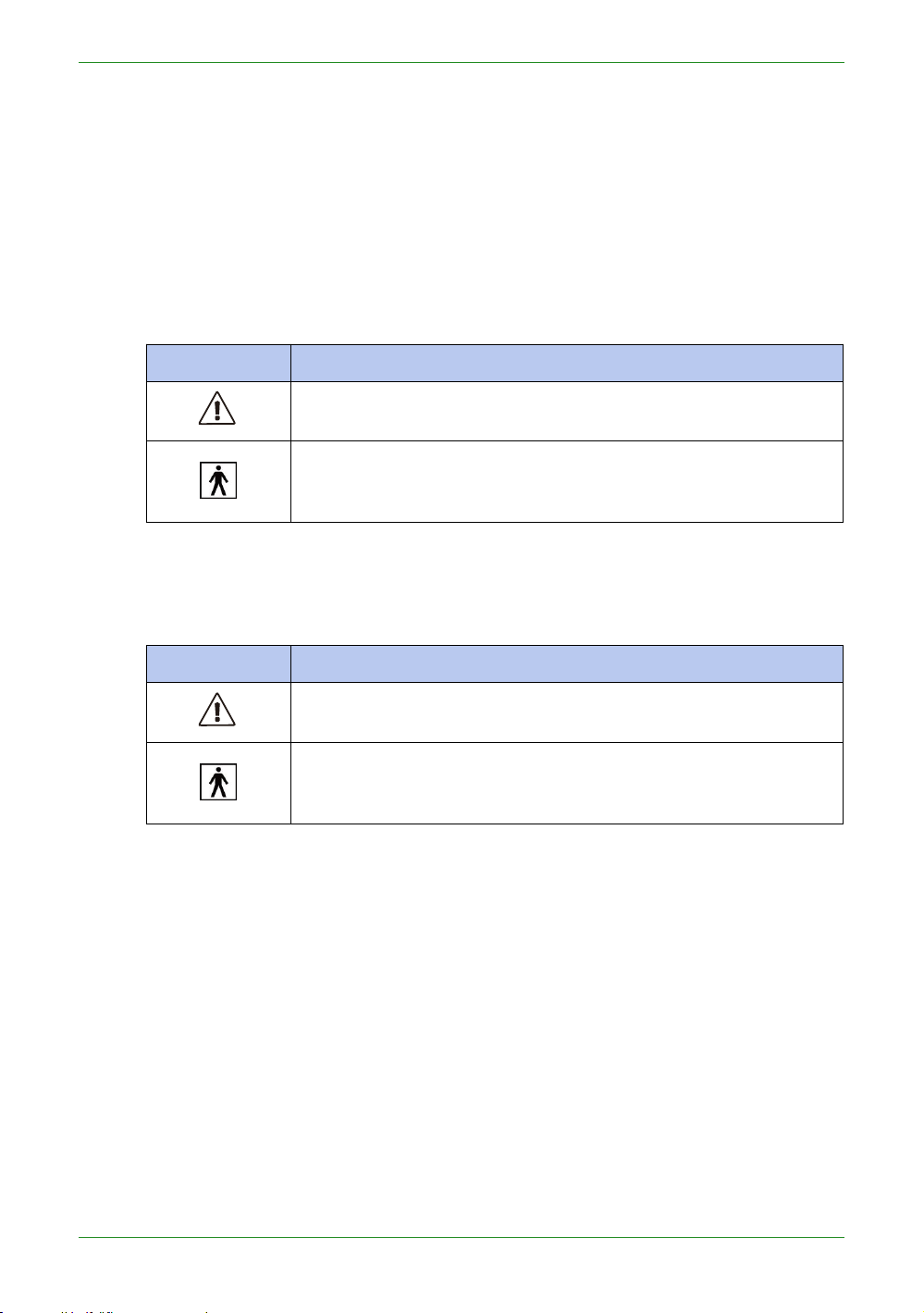
Legend of labels and symbols
Table 2-1 Labels and symbols on the device
Symbol
Explanation
General warning – caution.
Indicates that the device complies with requirements for the BF
type applied part according to IEC 60601-1, providing protection
against electric shock.
Symbol
Explanation
General warning – caution.
Indicates that the device complies with requirements for the BF
type applied part according to IEC 60601-1, providing protection
against electric shock.
The following symbols provide information on the product’s labels and regulatory
compliance.
On the device
On the carry box/package
Table 2-2 Labels and symbols on the carry box/package

12
Intraoral Scanner User Manual
Table 2-2 Labels and symbols on the carry box/package
Indicates that the user should read the operating instructions for
information on using this equipment.
Indicates that the final disposal of the device complies with Waste
Electrical & Electronic Equipment and waste regulations. It
can
no
longer be used for its intended purposes.
General warning – caution.
Indicates that the contents of the transport package are fragile
and therefore shall be handled with care.
Indicates that the transport package shall be kept dry.
Indicates correct upright position of the transport package.
Indicates the stack limits. A maximum of 6 units of identical
packages may be stacked.
Indicates temperature limits. The product must be stored in the
original shipping package in environments between -25°C and
60°C.
Indicates the humidity limits. The product must be stored in the
original shipping package in environments with 30% to 75%
relative humidity and noncondensing.
Indicates the atmospheric pressure limits. The product must be
stored in the original shipping package in environments between
700 hPa and 1060 hPa air pressure.
Indicates that the material shall be recycled.

13
Intraoral Scanner User Manual
Compliance
Anyone creating or changing a medical electrical system through a combination with
other devices in accordance with standard EN 60601-1-1:2001 based on 60601-11:2000 (specification for the safety of medical electrical systems)/UL 60601-1 Part 1:
first edition 2003 is responsible for ensuring that the requirements of these standards
are met to the full extent in order to ensure the safety of patients, operators and the
environment.
FCC compliance statement
This device complies with part 15 of the FCC Rules. Operation is subject to the
following two conditions: (1) This device may not cause harmful interference, and (2)
this device must accept any interference received, including interference that may
cause undesired operation.
Electrical safety
Only trained medical personnel should operate this scanner. The product complies
with the following standards:
Electrical
• IEC 60601-1-2:2014
• IEC 60601-1:2015/A1:2012 (ed 3.1)
• IEC 60601-1-6: 2013.Con Ed 3.1 Rev. October 29. 2013.
• IEC 62366-1:2015
• IEC 62304:2006/AMD1:2015
Classification
• Type of protection against electric shock: Class II
• The degree of protection against electric shock: Type BF
• The mode of operation: Continuous operation
• Pollution degree 2
For maximum safety, observe the following guidelines strictly:
WARNINGS
• Shock hazards exist if the power adapter is damaged or is not properly
grounded. Use only the supplied medical grade power adapter.
• To avoid the risk of electric shock, connect the scanner only to properly
grounded wall outlets.
• Only authorized service labs can make internal replacements of the
scanner and modify the software.

14
Intraoral Scanner User Manual
• Do not use the scanner if its tip or cable is damaged. Contact technical
Emission
measurement
Conformity
Electromagnetic environment -
guidelines
RF emissions
CISPR 11
Group 1
The Aoralscan 2 uses RF energy only
for its internal function. Therefore, its RF
emissions are very low and are not likely
to cause any interference in nearby
electronic equipment.
RF emissions
CISPR 11
Class B
The Aoralscan 2 is suitable for use in
all establishments, including domestic
establishments and those directly
connected to the public low-voltage
power supply network that supplies
buildings used for domestic purposes.
Harmonic emissions
IEC 61000-3-2
Class D
Voltage fluctuations/
flicker according
IEC 61000-3-3
Complies
support for replacement of the damaged equipment (see Contact
information on chapter 1).
• To avoid risk of electrical shock hazards, always inspect the scanner and
cable connections before use.
• Check the cable housing before use. Do not use if the housing is damaged
or the cable is abraded.
• All devices connected to the Aoralscan 2 shall comply with IEC 60601-1 and
IEC 60950.
EMC notice
Electromagnetic emissions
Medical electrical equipment such as the Aoralscan 2 requires special
precautions regarding electromagnetic compatibility, and must be installed and put
into service according to the following electromagnetic tables.
The Aoralscan 2 is intended for use in the electromagnetic environment specified
below. The customer or user of the Aoralscan 2 should assure that it is used in
such an environment.
Table 2-3 Guidance and manufacturer’s declaration – electromagnetic emissions

15
Intraoral Scanner User Manual
Interference immunity
Immunity test
IEC 60601
test levels
Compliance
level
Electromagnetic
environment – guidance
Electrostatic
discharge
(ESD)
IEC 61000-4-2
±8 kV contact
±15 kV air
±8 kV contact
±15 kV air
Floors should be wood,
concrete or ceramic tile. If
floors are covered with
synthetic material, a relative
humidity of at least 30% is
recommended.
Electrical fast
transient/burst
IEC 61000-4-4
±2 kV for
power supply
lines
±1 kV for
input/output
lines
±2 kV for
power supply
lines
±1 kV for
input/output
lines
Mains power quality should be
that of a typical commercial or
hospital environment.
Surge
IEC 61000-4-5
±1 kV line(s)
to line(s)
±2 kV line(s)
to earth
±1 kV
differential
mode
±2 kV
common
mode
Mains power quality should be
that of a typical commercial or
hospital environment.
The Aoralscan 2 is intended for use in the electromagnetic environment specified
below. The customer or user of the Aoralscan 2 should assure that it is used in
such an environment.
Table 2-4 Guidance and manufacturer’s declaration – electromagnetic immunity

16
Intraoral Scanner User Manual
Table 2-4 Guidance and manufacturer’s declaration – electromagnetic immunity
Immunity test
IEC 60601
test levels
Compliance
level
Electromagnetic
environment – guidance
Voltage dips,
short
interruptions
and voltage
variations on
power supply
input lines
IEC 61000-411
0% U
T
(100% dip in
UT) for 0.5/1
cycle
a
40% U
T
(60% dip in
UT) for 5
cycles
70%
UT(30%
dip in UT) for
25/30 cycles
a
(for
0.5 sec)
0% U
T
(100% dip in
UT) for 250/
300 cycles
a
(for 0.5 sec)
0% U
T
(100% dip in
UT) for 0.5/1
cycle
a
40% U
T
(60% dip in
UT) for 5
cycles
70%
UT(30%
dip in UT) for
25/30 cycles
a
(for
0.5 sec)
0% U
T
(100% dip in
UT) for 250/
300 cycles
a
(for 0.5 sec)
Mains power quality should be
that of a typical commercial or
hospital environment. If the
user of the Aoralscan 2
requires continued operation
during power mains
interruptions, it is
recommended that the
Aoralscan 2 be powered from
an uninterruptible power supply
or a battery.
Power
frequency (50/
60 Hz)
magnetic field
IEC 61000-4-8
30 A/m
30 A/m
Power frequency magnetic
fields should be at levels
characteristic of a typical
location in a typical commercial
or hospital environment.
If image distortion occurs, it
may be necessary to position
the Aoralscan 2 further from
sources of power frequency
magnetic fields or to install
magnetic
shielding.
The power
frequency magnetic field
should be measured in the
intended installation location to
assure that it is sufficiently low.
NOTE: UTis the a.c. mains voltage prior to application of the test level.
a
For example, 10/12 means 10 cycles at 50 Hz or 12 cycles at 60 Hz.

17
Intraoral Scanner User Manual
Table 2-4 Guidance and manufacturer’s declaration – electromagnetic immunity
Immunity test
IEC 60601
test levels
Compliance
level
Electromagnetic
environment – guidance
Conducted RF
3 Vrms
150 kHz to
80 MHz
outside ISM
bands
c
3 Vrms
Portable and mobile RF
communications equipment
should be used no closer
to
any
part of the Aoralscan,
including cables, than the
recommended separation
distance calculated from the
equation appliance to the
frequency of the
transmitter.
Recommended separation
distance:
d = 1.2 √P
IEC 61000-4-6
Radiated RF
IEC 61000-4-3
6 Vrms
150 kHz to
80 MHz in
ISM bands
c
3 V/m
80 MHz to
2.7 GHz
6 Vrms
3 V/m
IEC 60601-1-2: 2007
d = 1.2 √P 80 MHz to 800 MHz
d = 2.3 √P 800 MHz to 2.5 GHz
IEC 60601-1-2: 2014
d = 2.0 √P 80 MHz to 2.7 GHz
Where P is the maximum
output power rating of the
transmitter in watts (W)
according to the transmitter
manufacturer and d is the
recommended separation
distance in meters (m).
Field strengths from fixed RF
transmitters, as determined by
an electromagnetic site
surveya, should be less than
the compliance level in each
frequency rangeb.
Interference may occur in the
vicinity of equipment marked
with following symbol:

18
Intraoral Scanner User Manual
Table 2-4 Guidance and manufacturer’s declaration – electromagnetic immunity
Immunity test
IEC 60601
test levels
Compliance
level
Electromagnetic
environment – guidance
NOTE 1: At 80 MHz and 800 MHz, the higher frequency range applies.
NOTE 2: These guidelines may not apply in all situations. Electromagnetic
propagation is affected by absorption and reflection from structures,
objects and people.
a
Field strengths from fixed transmitters, such as base stations for radio (cellular/
cordless) telephones and land mobile radios, amateur radio, AM and FM radio
broadcast and TV broadcast cannot be predicted theoretically with accuracy. To
assess the electromagnetic environment due to fixed RF transmitters, an
electromagnetic site survey should be considered. If the measured field strength
in the location in which the Aoralscan 2 is used exceeds the applicable RF
compliance level above, the Aoralscan 2 should be observed to verify normal
operation. If abnormal performance is observed, additional measures may be
necessary, such as reorienting or relocating the Aoralscan 2.
b
Over the frequency range 150 kHz to 80 MHz, field strengths should be less than
3 V/m.
c
The ISM (industrial, scientific and medical) bands between 150 kHz and 80 MHz
are 6.765 MHz to 6.795 MHz; 13.553 MHz to 13.567 MHz; 26.957 MHz to 27.283
MHz; and 40.66 MHz to 40.70 MHz.
To limit exposure to electromagnetic interference from nearby equipment that can
degrade image quality or launch warning messages, it is necessary to position the
Aoralscan 2 further from sources of electromagnetic interference or install
electromagnetic shielding to block unwanted interference. The customer or the user
of the Aoralscan 2 should operate the device under EMI conditions that minimize
power supply transients, mechanical interactions, vibration, and thermal, optical, and
ionizing radiation.

19
Intraoral Scanner User Manual
Separation distances
Rated
maximum
output
power
of
transmitter
(W)
Separation distance according to frequency of
transmitter
(m)
IEC 60601-1-2 : 2007
IEC 60601-1-2 : 2014
150 kHz
to
80
MHz
d = 1.2
√P
80 MHz to
800 MHz
d = 1.2 √P
800
MHz
to
2.5
GHz
d = 2.3
√P
150 kHz
to
80
MHz
d = 1.2
√P
80 MHz to
2.7 GHz
d = 2.0 √P
0.01
0.12
0.12
0.23
0.12
0.20
0.1
0.38
0.38
0.73
0.38
0.63
1
1.2
1.2
2.3
1.2
2.0
10
3.8
3.8
7.3
3.8
6.3
10012122312
20
For transmitters rated a maximum output power not listed above, the
recommended separation distance d in meters (m) can be estimated using the
equation applicable to the frequency of the transmitter, where P is the maximum
output power rating of the transmitter in watts (W) according to the transmitter
manufacturer.
NOTE 1: At 80 MHz and 800 MHz, the separation distance for the higher frequency
range applies.
NOTE 2: These guidelines may not apply in all situations. Electromagnetic
propagation is affected by absorption and reflection from structures,
objects and people.
The Aoralscan 2 is intended for use in the electromagnetic environment in which
radiated RF disturbances are controlled. The customer or the user of the Aoralscan
2 can help prevent electromagnetic interference by maintaining a minimum distance
between portable and mobile RF communications equipment (transmitters) and the
Aoralscan 2 as recommended below, according to the maximum output power of the
communications equipment.
Table 2-5 Recommended separation distances between portable and mobile RF communications
equipment and the Aoralscan 2
The medical electrical equipment is suitable for the professional healthcare
environment per 60601-1-2:2014. It is suitable for use in physician offices, clinics,
hospitals, and other professional healthcare environments except near HF surgical
equipment and the RF shielded room of an ME system for magnetic resonance
imaging or other environments where the intensity of electromagnetic disturbances is
high.
The clinical environments where the device can be used include physician offices,
clinics, hospitals, and clinical point-of-care for diagnosis of patients except
environments where the intensity of electromagnetic disturbances is high.

20
Intraoral Scanner User Manual
WARNINGS
• Portable RF communications equipment (including peripherals such as
antenna cables and external antennas) should be used no closer than 30
cm (12 inches) to any part of the Aoralscan 2, including cables specified
by the manufacturer. Otherwise, degradation of the performance of this
equipment could result.
• If higher IMMUNITY TEST LEVELS than those specified in IEC60601-1-2
Table 9 are used, the minimum separation distance may be lowered. Lower
minimum separation distances shall be calculated using the equation
specified in IEC60601-1-2 Chapter 8.10.

21
Intraoral ScannerUser Manual
CHAPTER
3
Overview
Benefits of the product
The Aoralscan 2 is designed to provide powder-free intraoral color
scanning, with higher speeds resulting in greater accuracy and less
time-lag for image acquisition. It can be used to scan a single tooth,
multiple teeth, and whole dental arches. The captured 3D digital
impressions of teeth and soft-tissue areas are designed to be used
in conjunction with the supplied software programs ,Dental Order
System Module which helps manage the patient information and
scanned records, and Scan module which assists you in acquiring
digital impressions and is capable of exporting the scan data (in
STL/OBJ format) to CAD/CAM systems for different purposes of
dental care.
Carry box list
Check the carry box for the following items. If any item is missing or
damaged, contact your place of purchase immediately.
1. 1 x Intraoral Scanner with a USB 3.0 upstream cable (length:
2
meters)
2. 1 x scanner cradle (12 Vdc, 1.67 A)
3. 1 x protection cap
4. 2 x scanner tip (1 is already attached to the intraoral scanner
when shipped)
5. 1 x Calibrator
6. 1 x USB 3.0 cable (for the connection between the cradle and
your computer; cable length: 1.5 meters)
7. 1 x USB 3.0 cable (for the connection between the Calibrator
and your computer; cable length: 1 meter)
8. 1 x medical grade AC/DC power adapter (manufacturer:
Adapter Technology Co., Ltd.; model name: ATM020-W120U;
input: 100-240 V, 50-60 Hz, 0.45-0.27 A; output: 12 Vdc,
1.67 A; cable length: 2
meters)

22
Intraoral Scanner User Manual
9. 1 x 2-in-1 USB dongle (the license key for authorized access the
8 9 10
WARNINGS
NOTE
We recommend that you keep all the original packaging components in a safe
IntraoralScan software program for Windows)
10. 1 x carry box
4
1
2 3 4 5
6 7
• AC plug types vary by country/region.
• Using accessories, peripherals, or cables not supplied with the product or
recommended by Shining3DCorporation can affect the device in the form
of increased emissions or decreased immunity to external EMI/EMC
occurrences. Non-specified peripherals, and cables in some cases, can
also increase leakage current or compromise the safety of the grounding
scheme.
• Using accessories or power supply units other than those specified may
cause the warranty to void and result in increased emissions, decreased
EMI immunity of the device, or even damages to the device and personal
injuries.
• Use of other accessories results in non-compliance.
• Always store the 2-in-1 USB dongle in a safe place for later use.
place in case you need to transport or dispose of the scanner in the future. For
details, see Storage for transport on chapter 9.
Software overview
The Aoralscan 2 is designed to operate with the software programs included two
modules (supplied in the 2-in-1 USB dongle):

23
Intraoral ScannerUser Manual
1. Dental Order System Module
Table 3-3 System requirements
CPU
Intel Core i7-8700 or higher
Memory
16 GB or higher
Hard drive
1 TB SATA Hard Drive (7200 RPM, 6.0 Gb/s) or
higher
Graphic card (GPU)
NVIDIA GTX 1070 6GB DDR3 or higher
(supporting NVIDIA CUDA)
Operating system
Windows 10 Professional (64-bit) or later versions
of Windows operating system
I/O ports
More than 3 Type-A USB 3.0 (or higher) ports
WARNING
Designed to manage and store patient data, including cases, prescriptions, and
restoration information,realizing functions such as order creation, editing,
searching, scanning and deletion, as well as uploading, downloading,
previewing and tracking of scanned order and data. 。
2. Scan Module
The interface guides you through the entire scanning process of acquiring
intraoral digital impressions via the scanner.
For information on how to use these software programs, see Using IntraoralScan on
chapter 7
System requirements
Before installing and running the supplied software programs, your computer shall
meet the following requirements:
The computer or notebook you use shall meet the safety requirements of
IEC 60601-1 and IEC 60950.

24
Intraoral Scanner User Manual
Scanner overview
No.
Component
Function
1.
Scanner tip
Use the tip to scan the upper jaw, lower jaw, or full jaw.
The tip(s) can be autoclaved up to 20 times.
2.
Heater
The anti-condensation heater prevents fogging on the
mirror to ensure successful scanning.
3.
Exhaust vents
Allows the heat produced by the operation of scanner to
be dissipated from the case.
4.
Intake vent
Allows the ambient cool air to enter into the case to help
cool down the heat produced by the operation of scanner.
NOTE
When scanning, do not hold the scanner in
the way that covers or blocks the intake and
exhaust vents. Otherwise the scanner may
become overheated.
5.
LED ring light
Indicates the status of your scanner.
• Blinking green: the scanner is in preparation/warm-up
mode.
• Solid green: the scanner is ready for use.
• Solid blue: the scanner is processing the alignment of
scanned data.
• Solid amber: an error occurs and needs your attention.
Table 3-1 Introduction to the scanner tip and scanner body
Tip and scanner body
1
2
6
3
3
Table 3-1 Introduction to the scanner tip and scanner body
4
5

25
Intraoral ScannerUser Manual
No.
Component
Function
6.
Scanner body
Hold the scanner body on the sides and rotate the
scanner body to obtain the best scan angle. The scanner
body may get warm during scanning, yet the temperature
won’t cause harm to the user and the patient.
Scanner cradle
6
5
3
4
No.
Component
Function
1.
Cradle
Place the scanner in the cradle when you are not using it.
2.
LED indicator
Indicates the status of the cradle.
• Solid green: power on.
• LED off: power off.
3.
Power switch
To receive power from the power outlet, turn it on; to stop
receiving power from the power outlet, turn it off.
4.
Power
connector
Connect the power plug from the supplied power adapter
to this power connector, and plug the power adapter to
the power outlet.
5.
USB
3.0
downstream
port
For connecting the scanner cradle and the USB port of
your computer using the supplied USB cable.
This port transfers data between the Aoralscan 2
and your computer.
6.
USB 3.0
upstream port
Connect the scanner cable to this port.
This port provides power supply and data communication
between the scanner and cradle. For details, see
Connecting the scanner on chapter 4.
NOTES
2
Table 3-2 Introduction to the scanner cradle
1
• When the scanner is left idle for 10 minutes (including being placed on a
26
Intraoral Scanner User Manual
desk), it will go into standby mode. After 1 minute of inactivity, it will
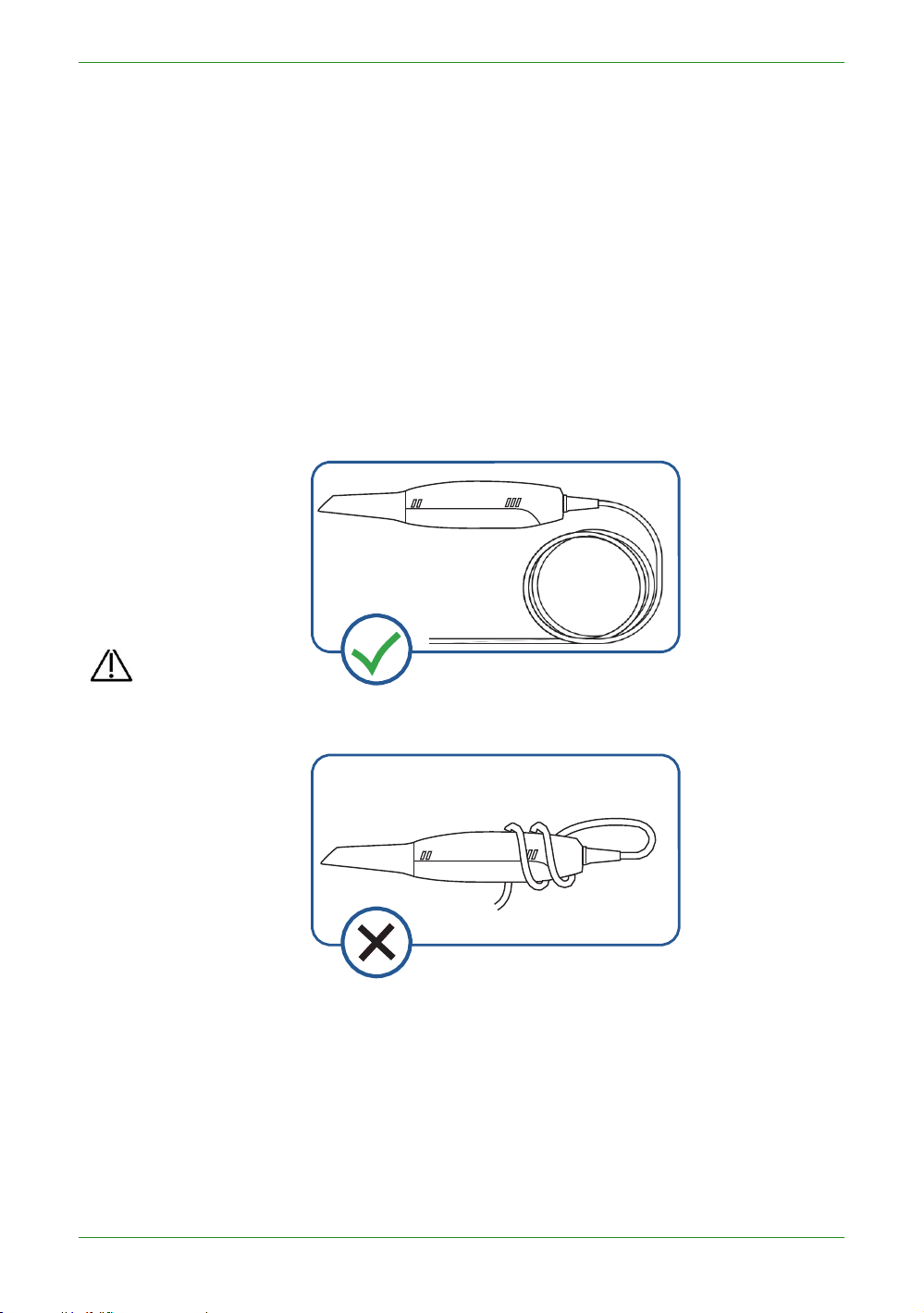
CAUTION
Do NOT roll the cable over the handle of the scanner or even bend the cable
automatically go into sleep mode, and the LED ring light on the end of the
scanner body will also go off.
• To activate the scanner, place it in the cradle. The scanner will go into
standby mode within 3 minutes. If the scanner is left idle for more than 1
minute, it will automatically go into sleep mode.
• To lower the temperature inside scanner body, the cooling fan still
operates for about 30 minutes after the scanner goes into standby or sleep
mode. Then it will stop spinning.
• The scanner tip is being heated whenever power is supplied, even if the
scanner is in standby or sleep mode.
USB cable storage
To prevent the USB cable from getting damaged by excessive bending or twisting,
you should loosely coil the cable and avoid making kinks or sharp bends.
sharply. The illustration below demonstrates improper cable storage.

27
Intraoral ScannerUser Manual
Installing the software programs
The supplied 2-in-1 USB dongle contains the IntraoralScan software program.
CAUTIONS
• Install the software programs in accordance with the instructions given
here.
• When the installation is completed, do not plug the power adapter to the
wall outlet or turn on the scanner yet. See Setting up the scanner on
chapter 4 for more necessary procedures to get started.
Follow the steps below to complete the installation of software programs:
1. Insert the supplied 2-in-1 USB dongle into the USB port of your computer.
2. Find the file named IntraoralScanX.X.X.X.exe and run it as administrator.
3. The IntraoralScan InstallShield Wizard window appears to start the
installation.
4. Specify a language from the drop-down list.
5. Click OK.
6. Follow the on-screen instructions to complete the installation.
When done, four shortcut icons, and , will appear on your
desktop for quick access.

28
Intraoral Scanner User Manual
CHAPTER
WARNING
Ensure that you use only the supplied power adapter,
4 Setting up the scanner
Connecting the scanner
CAUTIONS
• Ensure the supplied software programs are installed
on your computer before the connection.
• Install the scanner in accordance with the
instructions stated in this User Manual.
• Use the scanner only in dental laboratories, dental
clinics, and equivalent environment.
• Do not install, place, and use the scanner in dusty
and damp environment or in the areas of
temperature extremes or in direct sunlight.
• Prepare a flat surface, e.g. your desk, for the scanner
and the cradle. Do not place them on a slanted
surface.
• Before the installation is completed, do not plug the
power adapter into the wall outlet or turn on the
scanner until you are instructed to do so.
• Always return the scanner to the cradle when it is
not in use. Do not place the scanner in heated or wet
surfaces as this can cause damage to the tip and
scanner.
• It is normal that the scanner gets warm when in use.
power cable, and USB cable.
29
Intraoral Scanner User Manual
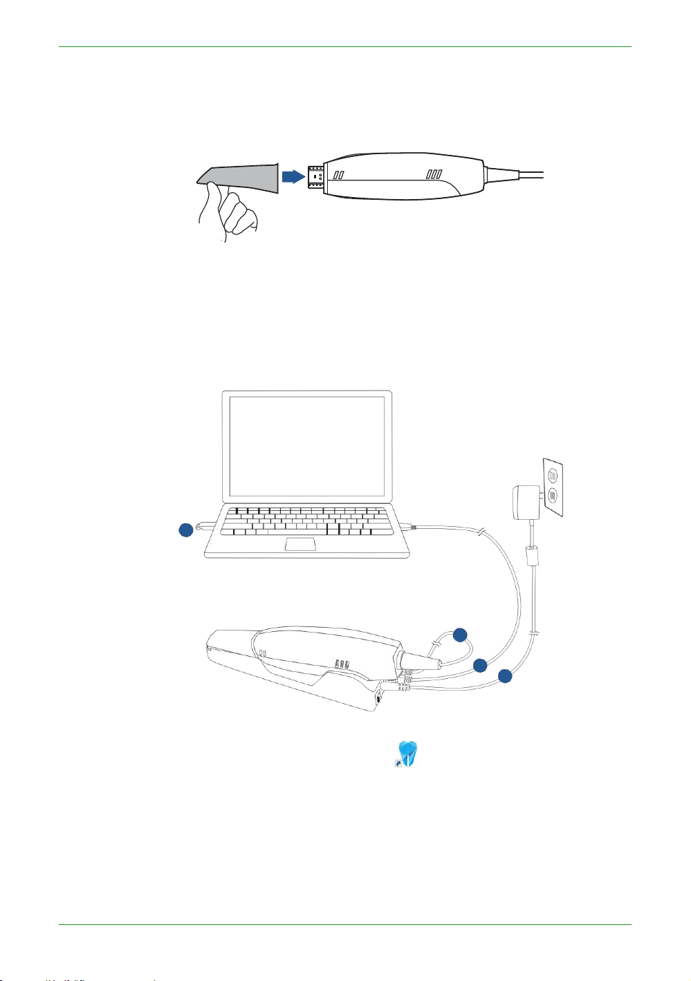
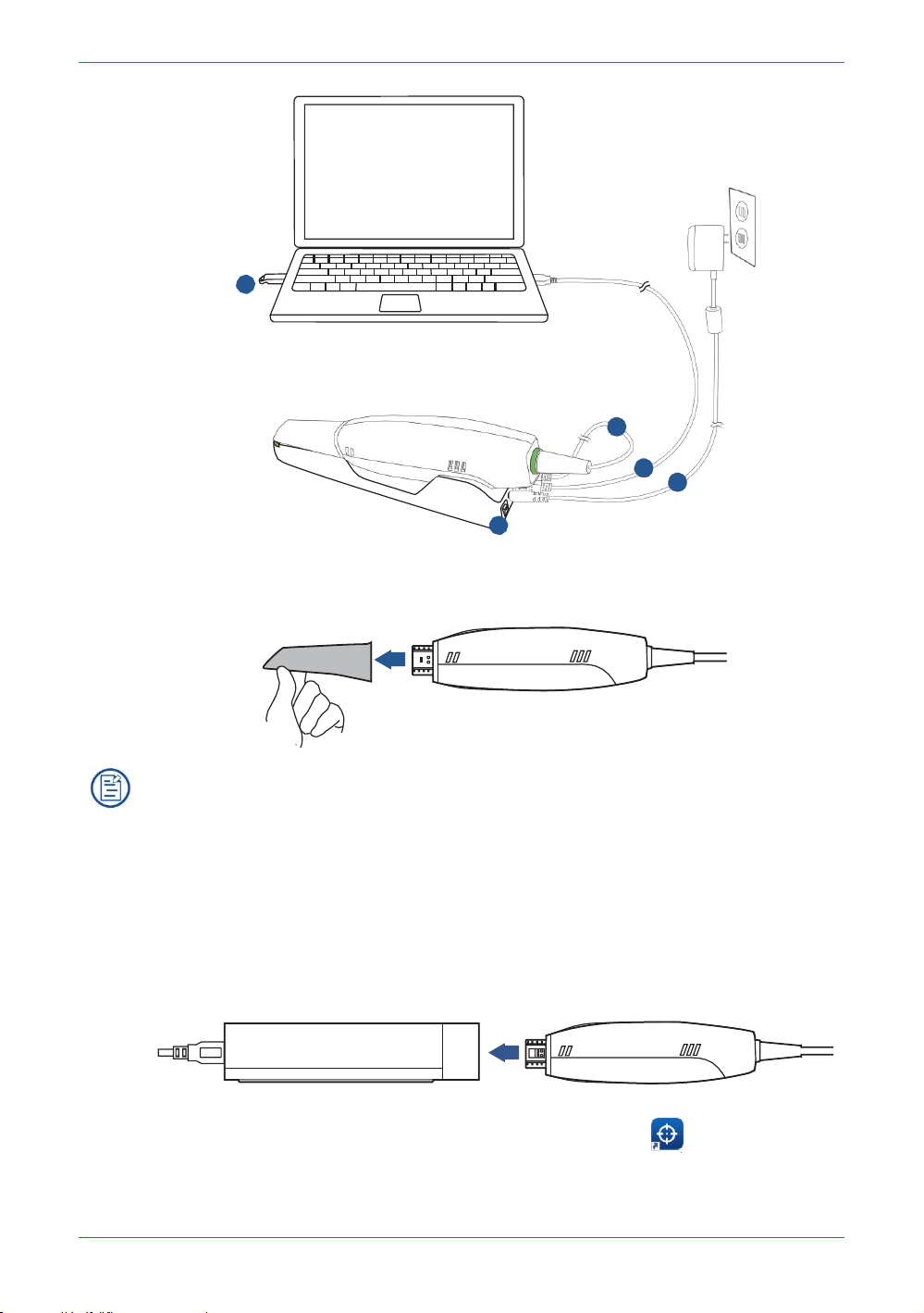
Follow the steps below to complete the connection:
6. Turn on the power switch on the cradle.
1. Make sure the scanner tip is firmly attached to the front end of the scanner;
otherwise, gently and firmly slide the scanner tip onto the front-end of the
scanner, as illustrated.
2. Insert the power plug of the supplied power adapter into the power connector
on the cradle, and plug the power adapter into a wall outlet.
3. Connect the scanner cable to the USB 3.0 upstream port on the cradle.
4. Connect the USB 3.0 downstream port on the cradle and your computer with
the supplied USB 3.0 cable.
5. Insert the supplied 2-in-1 USB dongle into the USB port of your computer.
software.
5
3
4
2
7. Click the shortcut icon of IntraoralScan on the desktop to launch the

30
Intraoral Scanner User Manual
Disconnecting the scanner
CAUTION
Do not attempt to directly disconnect the scanner by removing the power cable
CAUTION
Do NOT roll the cable over the handle of the scanner or even create any sharp
and USB cable.
Follow the steps below to safely disconnect the scanner:
1. Quit the IntraoralScan scanning software.
2. Turn off the power switch on the cradle.
3. Disconnect the scanner cable from the cradle.
4. Disconnect the USB 3.0 cable from the USB 3.0 downstream port on the cradle
and your computer.
5. Right-click the “Safely Remove Hardware” icon on Windows taskbar and select
“Eject Flash Drive”.
6. Unplug the 2-in-1 USB dongle and keep it in a safe place for future use.
7. Unplug the power adapter from the wall outlet and remove the power plug from
the power connector on the cradle.
bends in the cable after you disconnect the scanner. See USB cable storage
on chapter 3 for more details.
Calibrating the scanner
Under these circumstances, we recommend that you shall execute the calibration for
the scanner to ensure the accuracy of scanned data:
• The initial setup of the scanner is completed.
• The scanner has been used for a period of time (e.g. 2 weeks).
• The scanner is accidentally dropped.
Follow the steps below to perform the calibration:
1. Insert the power plug of the supplied power adapter into the power connector
on the cradle, and plug the power adapter into a wall outlet.
2. Connect the scanner cable to the USB 3.0 upstream port on the cradle.
3. Connect the USB 3.0 downstream port on the cradle and your computer with
the supplied USB 3.0 cable.
4. Turn on the power switch on the cradle.
The LED light ring on the end of the scanner body lights up green when the
power connection is working properly.
5. Insert the supplied 2-in-1 USB dongle into the USB port of your computer.
31
Intraoral Scanner User Manual
5
3
1
2
4
6. Hold the scanner tip firmly with your thumb and forefinger on both sides, and
then gently slide the tip off from the scanner, as illustrated.
NOTES
• Do not place your finger(s) on the mirror of the tip when detaching as this
may result in damage to the mirror.
• Store the detached tip in a safe place, e.g. a dental instrument tray, for
future use.
7. Connect the on the supplied Calibrator and your computer with the
USB 3.0 cable.
8. Gently slide the Calibrator onto the front end of the scanner, as
supplied
illustrated.
9. Double-click the shortcut icon of IntraOralCalibration . Display the
following screen.

32
Intraoral Scanner User Manual
10. Click Calibration.If the Calibrator was not closely plugged onto the scanner, a
11. Click Start. The status bar shows the percentage of completion.
NOTE
It is normal that the calibration takes approximately 5 minutes.
warning message would be popped. So, make sure the scanner be plugged into
the calibration firmly before next operation.
12. The following message appears once the calibration is completed. Click OK to
exit.

33
Intraoral Scanner User Manual
13. Gently slide the Calibrator off the scanner.
CAUTION
Make sure that the Calibrator is removed from the scanner after the
calibration is done. Otherwise, the Calibrator may get very warm.
14. Re-attach the scanner tip to the scanner for later use or put the protection cap
onto the scanner to prevent damage and dust.

34
Intraoral Scanner User Manual
CHAPTER
WARNING
Concerning hand hygiene and personnel safety when
5 Scanning preparation
Scanning basics
Read and follow the guidelines and tips given in this chapter prior to
acquiring quality images.
performing a scan, you must wear clean surgical
gloves through the whole process.
Tooth preparation
• Ensure that saliva is not blocking the vision of the working area
for the scanner user. Dry the working area (lips, tongue, and
tissues) whenever needed.
• If necessary, ask the patient to hold the tongue still and move it
to the opposite side of the mouth.
• Dry the teeth thoroughly before starting a scan.
• When scanning, consider using the saliva ejector and tampons
to keep the surfaces of teeth dry.
• If necessary, consider using the retractors to avoid excessive
tissue from being scanned.
• If necessary, consider using tampons to help create space
while working on narrow regions between teeth.
Scanner preparation
• Ensure that the scanner tip, scanner body, and cradle are
properly pre-cleaned, disinfected, or sterilized. See Precleaning, disinfection, and sterilization on chapter 9.
• Ensure that the scanner tip has no scratches or is not
damaged. Additionally, the tip is firmly attached to the front end
of the scanner body.

35
Intraoral Scanner User Manual
• Ensure that the scanner connection is ready; it is correctly connected to a power
source and powered on, and IntraoralScan are launched and ready to work.
• To avoid condensation on the mirror of the tip when scanning, the scanner tip
must have been warmed up. For details, see Heating the scanner tip on chapter 5.
• Calibrate the scanner and verify the accuracy of the acquisition regularly. For
details, see Calibrating the scanner on chapter 4.
Scanning position and path
• Avoid direct light from any light source, e.g. dentist chair lamp, to shine on the
area you are working on.
• Hold the scanner steady by resting it on the tooth surface and keep the scanner
tip within 15 mm from the teeth.
• When scanning, slowly move the scanner and simultaneously check the scan
results on the screen to ensure the scanning is of good quality.
• When scanning, the scanner tip should be centered over the teeth, and each
movement should align with the cross-hairs, following the lower and upper dental
arch shapes.
• A complete scan data of a single area includes the surfaces of occlusal, lingual,
buccal, interproximal contacts of the adjacent teeth, and 2-3 mm buccal gingiva.
• A complete scan data of a single case includes the lower jaw, upper jaw, and bite
registration.
• When scanning, change the scanning angle to 35-55 degrees in order to create
overlaps. It is important to achieve an overlap of at least 30% between each
acquisition. If the overlap is small, it may cause the alignment to fail.
• To scan the occlusal surface of the teeth, hold the scanner at a 90-degree angle;
to scan the buccal and lingual surfaces of the teeth, hold the scanner at a 45degree angle.
• Inspect the scanned image in the 3D scan view window (IntraoralScan) and
pay attention to warning messages.
Heating the scanner tip
In order to obtain optimal image quality, you should prevent condensation on the
scanner mirror before each scan by heating the scanner tip.
Follow the steps below to warm up the scanner before starting an acquisition:
1. Ensure that the scanner tip, scanner body, and cradle are clean and sterile. For
details, see Pre-cleaning, disinfection, and sterilization on chapter 9.
2. Gently and carefully attach the scanner tip to the scanner body, with the mirror
facing
downward
.

36
Intraoral Scanner User Manual
3. Connect the power supply to the Aoralscan 2. For details, see
Connecting the scanner on chapter 4.
4. Place the scanner in the cradle to secure it in place.
5. When the LED ring light on the end of the scanner body lights up green, the
heater automatically turns on and detects the temperature.
It the temperature of the scanner tip is lower than the set point for anti-fogging,
a notification message of pre-heating and current temperature appears.
When the message disappears, the warm-up is done. The scanner is now
ready for an acquisition.
NOTES
• The heater maintains constant temperature on the scanner tip.
• The scanner tip is being heated whenever power is supplied, even if the
scanner is in standby or sleep mode.
• If the heater does not reach the necessary temperature for preventing
condensation during scanning, the message of “The scanner is preheating. Please wait” appears.

37
Intraoral Scanner User Manual
CHAPTER
6 Clinical case quick guide
Connection the scanner
See Chapter 4-Connecting the scanner for detail.
Calibration
See Chapter 4-Connecting the scanner” for details.In order to ensure
the quality of the scanned data, it is necessary to perform calibration
periodically (recommended every 15 days).
Create order
Double-click desktop icon and the software will open the
Dental Order System.Click Project and select New to create a new
order. Fill out the necessary order information, including the names
of dentist(s), patient, and lab(s). Or select Load to open an existing
project.
Select the desired type of restoration and the tooth number (the
restoration site), and then click Save.)

38
Intraoral Scanner User Manual
Finally, click the "Scan" button to automatically open Intraoral Scan interface.
Scan upper jaw
Confirm that the image of the camera window in the upper right corner of the software is
displayed normally. Click the Scan button or the space bar to start scanning.
If it prompts "Please remove the scanner from the tooth for optimization", then remove the
scanner for data optimization, and continue scanning after optimization is completed.

39
Intraoral Scanner User Manual
The green frame in the middle of the software interface indicates the data range of the current
scanning. If the green frame changes to a red frame, as shown in the figure below, the scan
position is incorrect. You need to move the scan head to scan the data displayed in the red
frame.
If there is more buccal tongue side data during the scanning process, it is recommended to
press the pause button to automatically delete, as shown below (effect image before
and after pause)
Confirm that the model scan is complete, click the Finish button or long press the space
bar to process and save the data. After the completion, the upper jaw icon is green and ticked,
indicating that the scanning process is finished.

40
Intraoral Scanner User Manual
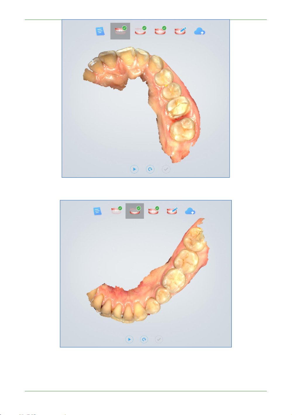
Scan lower jaw
The upper jaw completes the scanning data processing and automatically jumps to the lower
jaw scanning process, which is the same as scanning the upper jaw.
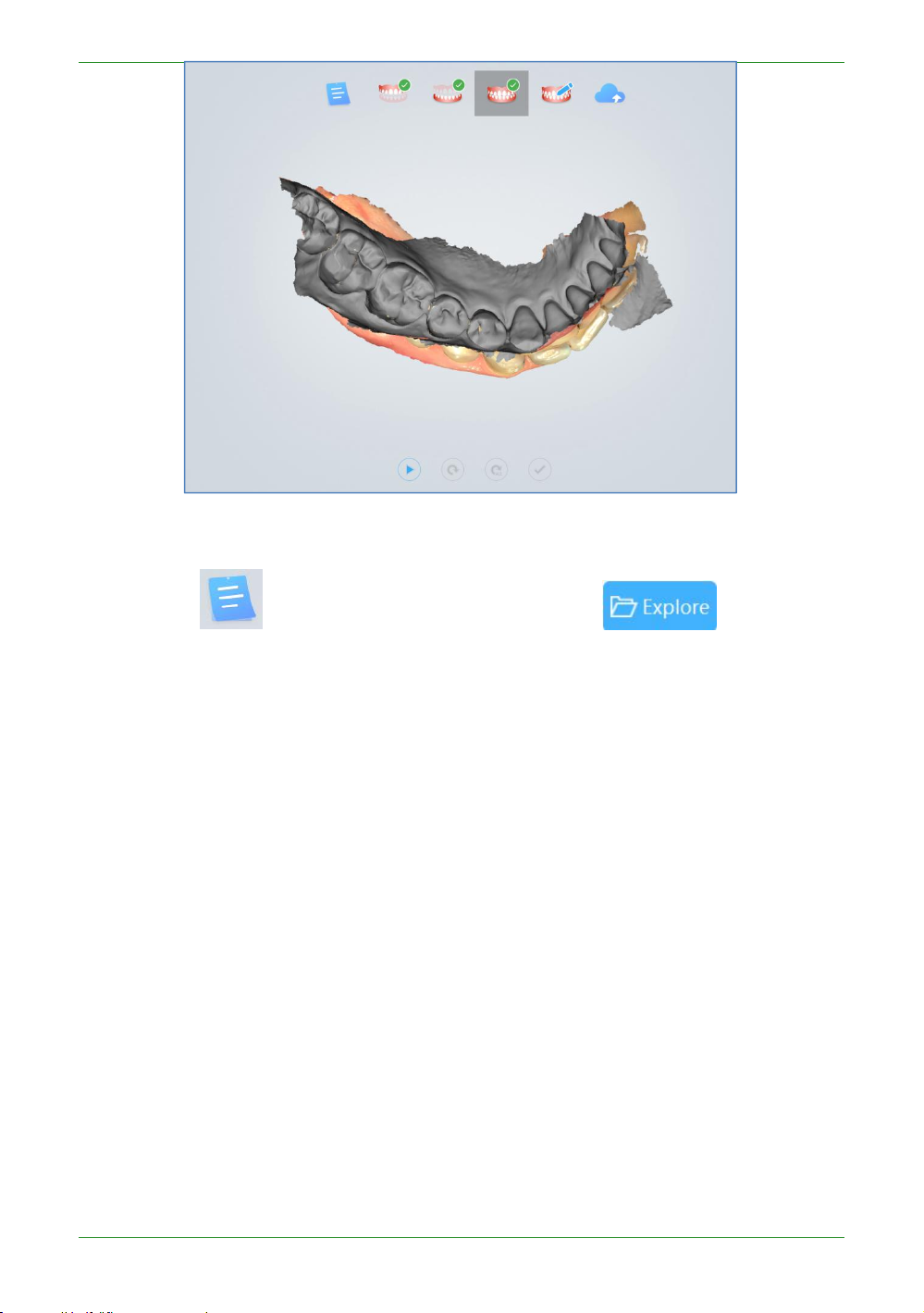
Scan total jaw
The lower jaw finish scan data processing ends and automatically jumps to the full jaw scan
procedure.
Click the scan button or the space bar to start scanning. After scanning some data, the
software automatically performs dynamic bite stitching, as shown below.
If the upper and lower jaw data and the full jaw data are occluded properly, click or
space bar to pause the scan to see the bite effect.
41
Intraoral Scanner User Manual
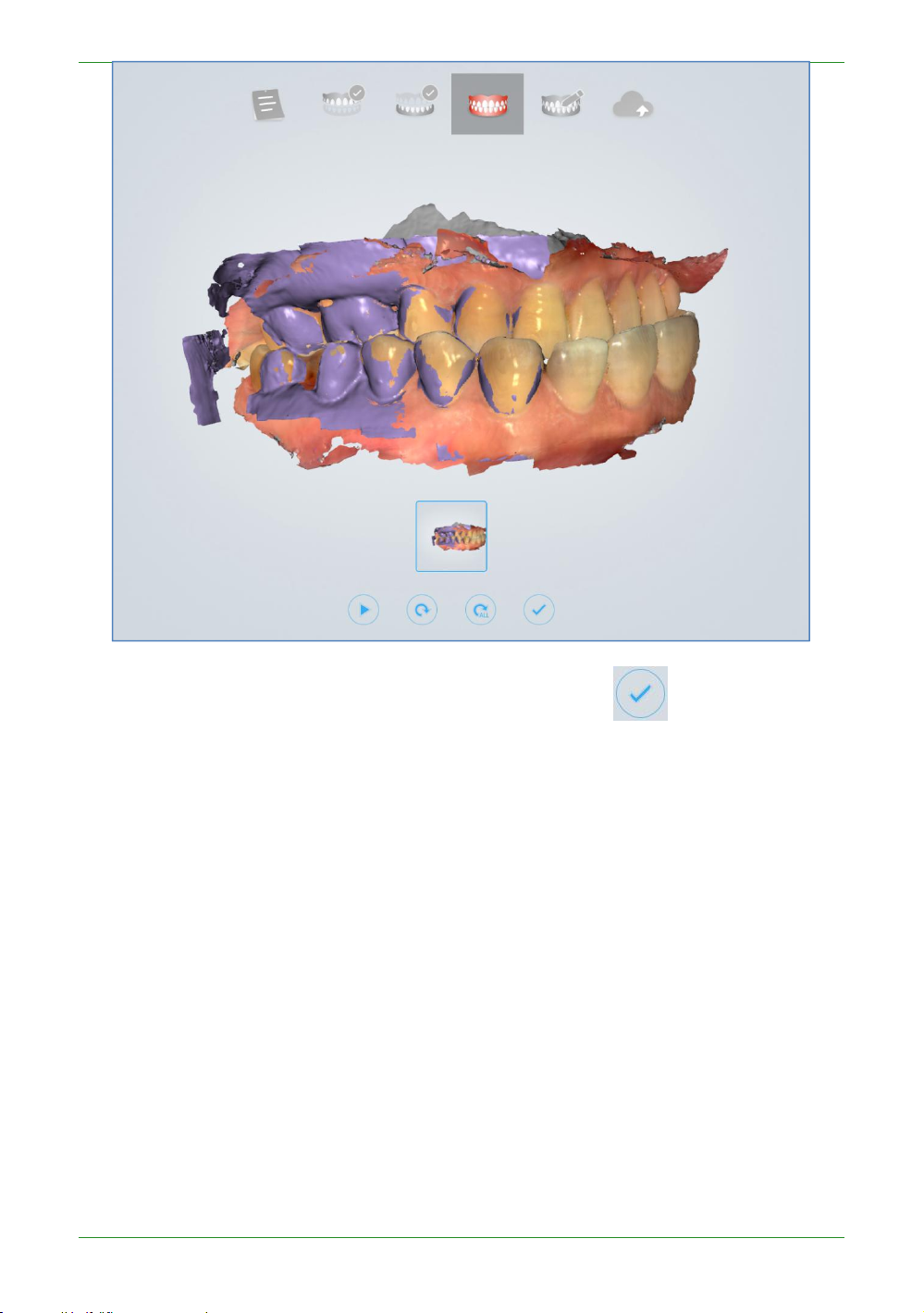
Confirm that the bite effect is appropriate. Click the Finish button or long press the
space bar to post-process the data.
View result data
View result data in IntraoralScan
View upper jaw
42
Intraoral Scanner User Manual
View lower jaw
View the occlusal effect
43
Intraoral Scanner User Manual
View data storage path
Click the button to return to the order interface and click to open the
folder path of the current order storage.

44
Intraoral Scanner User Manual
Pre-Design
See Chapter 7 "Pre-Design" for details on pre-design functions.
Upload order
Click icon to upload the scanned order. If you have not logged in, the software
will prompt “No login to the account, go to the setup interface to log in?”, select “Yes” to open
the “Configure Account” interface. Register the account on the webpage of the dental cloud,
add the lab, refer to Chapter 9 “Registering Account” and “Building Relationship Network”.
Then return to the Dental Order System login account, after the login is successful, upload the
order.

45
Intraoral Scanner User Manual

46
Intraoral Scanner User Manual
CHAPTER
7 Using IntraoralScan
Introduction to IntraoralScan
IntraoralScan
and scan module.Dental order system is a module for dental order
management, realizing management functions such as order
creation, editing, searching, scanning and deletion, as well as
uploading, downloading, previewing and tracking of scanned order
and data. The scan module collects oral digital images, processes
rendering data and outputs 3D data (STL/OBJ).
includes two modules: dental order system module
Note
To run software, the following requirements must be met:
• The supplied 2-in-1 USB dongle is plugged into the USB port of
your computer.
• The connection between the scanner and your computer is
ready. For details, see chapter 4-Connecting the scanner.

47
Intraoral Scanner User Manual
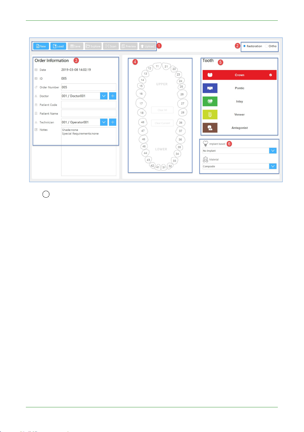
Introduction to Dental Order System
Double-click the desktop icon , open the software to dental order system, the
interface is as follows:
The dental order system is mainly composed of three parts, 1. order information; 2.
order list; 3. setting.
48
Intraoral Scanner User Manual
Information
1
Button column
New: Create a new order.
Load: Load a saved order.
Save: Save the new order with the completed order information.
Explore: Open the folder where the saved order is located.
Scan: Start scanning.
Preview: After the order scan is completed, the scanned data is viewed through
Upload: After the order scan is completed, the current order data is uploaded to
the DentalViewer.
the dental cloud.

49
Intraoral Scanner User Manual
Choose lab: choose a lab in drop-down list
Review design data: Does the design data of the lab need a doctor to review it?
The default is yes.
Cancel: Cancel the upload.
Confirm and Upload: Confirm upload order data to the dental cloud.
exo Design: After the order scan is completed, open the EXOCAD design software
2 Order Type: Restoration and Ortho.
3 Order Information: Set the order number, doctor, patient, lab and notes
4
teeth map
Left mouse button to select the tooth position.
Right mouse button to cancel the defined repair type.
Ctrl+left mouse button, copy the repair type defined by the previous tooth position
Shift+left mouse button, copy the type of repair defined by the previous tooth to
directly for design. The first time you click this button, you need to set the path of
the EXOCAD design software first.
information.
to the currently selected tooth position.
all the teeth between the tooth position of the same jaw and the last tooth
position.

50
Intraoral Scanner User Manual
Clear Current: Clears the defined repair type of the currently selected tooth
Clear all: Clear all defined types of fixes for the teeth position.
5
Types of dental restoration: crown, pontic, inlas, venees and antagonist. The
crown is selected by default.
6 Implant based and Material: Set the planting type and materials. The type of
1
Refresh: Refresh the order list
2
Import Order: Import orders that are not stored in the order path. If the import
3
Search: Search by order date or by entering a doctor/patient/lab.
4
Order Status: Lists all status of the order, which can be filtered by order status.
Need Scan: orders that have not been scanned. The right-click menu or operate
dental restoration is defined as the crown to set the type of implant.
Order List
The order list lists the order status of all orders under the dental order path.
position.
is successful, it will be displayed in the first line of the list. If an order with the same name
already exists in the order path, the imported order is automatically renamed to "source
order name +_import_*".
icons for such orders are: Load/Open in Explore/Duplicate/Delete.

51
Intraoral Scanner User Manual
Need Upload: Orders that have been scanned and have not uploaded order data to
the dental cloud. The right-click menus or operate icons for such orders are:
Waiting Accept: The order data has been uploaded to the dental cloud, waiting for
Accepted: The lab has received the order and waits for the order of the design plan.
Need Confirm Design: The lab has uploaded the design plan and the doctor has not
Making: The design plan has been approved by the doctor, and the order of the lab
Delivering: The lab has shipped the goods, and the doctor has not received the
Finished: The doctor has confirmed the order for the goods received. The right-
Rejected: The order data has been uploaded to the dental cloud, and the lab
Canceled: Order data has been uploaded to the dental cloud, and the doctor has
5
The descriptions for orders operation icons.
Icon Example
Description
Load/Open in Explore/Duplicate/Delete/Upload.
the order received by the lab. The right-click menus or operate icons for such
orders are: Load/Open in Explore/Duplicate/Cancel Order/Delete/Re-upload.
The right-click menus or operate icons for such orders are: Load/Open in
Explore/Duplicate/Delete/Cancel Order.
reviewed the approved order. The right-click menus or operate icons for such
orders are: Load/Open in Explore/Duplicate/Delete/Download Design/Confirm
Design/Request Re-design.
is making. The right-click menus or operate icons for such orders are: Load/Open in
Explore/Duplicate/Delete/Download Design/Request Re-design.
order for the goods. The right-click menus or operate icons for such orders are:
Load/Open in Explore/Duplicate/Delete/Download Design/Delivery
Information/Confirm Received/Request Re-delivery.
click menu or operate icons for such orders is: Load/Open in
Explore/Duplicate/Delete.
refused to accept the order. The lab can refuse to accept orders before uploading
the design. The right-click menus or operate icons for such orders are: Load/Open
in Explore/Duplicate/Delete/Re-Upload.
cancelled the order. Doctors can refuse to take orders before the labs upload the
design. The right-click menu or operate icons for such orders is: Load/Open in
Explore/Duplicate/Delete.

52
Intraoral Scanner User Manual
Load the currently selected order.
Open the folder where the currently selected order is
located.
Duplicate the currently selected order to a new order.
Delete the currently selected order form the order
list,you can choose whether to delete stored order files
and scaned data.
Upload
the currently selected order to the dental cloud .
Order data has been uploaded to the dental cloud, and
the doctor has cancelled the currently selected order.
Download Design.
Confirm Design.
Request Re-design.
Delivery Information.
Request Re-delivery.

53
Intraoral Scanner User Manual
Confirm Received.
Setting
1
Save EXO order: Save the order while saving the exocad order *.dentalProject, EXO
2
Save the third-party order: Save the order and save the order of the third-party
3
User interface language: User setting software interface language,Chinese (Simplified)
4
Dental Notation: FDI World Dental Federation notation and Universal numbering
5
Dental Model Viewer Path:Set the path of the DentalViewer program .After the order
Users can view or set specific information through the setting button
on the software interface.
design software to import the order, you can directly design. The default is on.
software. Generate thirdParty\*.xml under the order path. The third-party design software can
import the order and directly design. The default is off.
and English. The default language is the language selected during software installation.
system, the default is FDI World Dental Federation notation.
scan is completed, the scanned data is viewed through the DentalViewer.

54
Intraoral Scanner User Manual
6
EXO DentalACD Path: Set the path of the EXOCAD program so that you can launch
the EXOCAD software instantly when you click the "Information" ->"exo Design" button.
7 Dental Order path: Set the order save path. The default is C:\DentalOrder.
8
Order File Naming Rule:Set the order file name.
(A) Default :Restore default,”Date_Doctor Code_Order ID”.
(B) Clear :Clear all the selected items except “Order ID”.
(C) Naming Rule items :
Order ID/Date/Doctor Code/Patient Code/lab
(D)Save :Save
the current setting.
(E)Cancel :
Cancel and discard the current setting
.
NOTE:
9
Privacy Policy: Unchecked by default. Users must check the “I have read and agree
Code/Order Number/Doctor Name/Patient Name/lab Name.
After modifying the setting "user interface language" / "Dental Notation" / “EXO
DentalACD Path”/"Dental Order path" /”Order File Naming Rule”information,
click ”Apply” button,show the "New setting will take effect after restart,do you want
to restart application now?" message box, click "Restart Now" button, auto restart
the software to take effect.

55
Intraoral Scanner User Manual
to the Privacy Policy” to activate the configuration information related to the dental cloud.
10
Set Account: Register or log in to the dental cloud account
①Login method: email login and mobile number login. You should log in to the
②Enter the login email account.
③Enter the login password.
④Register: Unregistered users click this link to go to the dental cloud website to
⑤Forget password: Forgot your password, click this link to go to the Dental
⑥Login: Fill in the correct account and password, login is successful, and the
⑦mobile phone account: first select the area, then enter the mobile number.
11
9 Adding a lab: If you have not added a lab, you can click this button to go to the
doctor or hospital/clinic account here, and you cannot log in to the lab's account.
register.
Cloud website to retrieve your password.
contact information filled in during registration is displayed in the upper left
corner of the software.
The default bit is the China region.
Dental Cloud website to add a network operation to establish a cooperative relationship with
the lab.

56
Intraoral Scanner User Manual
12
10 Refresh: Refresh the list of dental lab.
13
11 Connected lab: List the accepted labs.
Data storage
The data save settings in the order directory, is saved by default in C:\DentalOrder,
named by date, as shown below
Navigating IntraoralScan interface
In the Dental Order System created order, saved it, and will scan. If no scanner is
connected, an error message appears to remind you to check and reconnect the
scanner.
NOTE
If the scanner is connected yet the error message
appears, remove then reconnect the scanner. If IntraoralScan still cannot detect

57
Intraoral Scanner User Manual
the scanner, quit IntraoralScan. Wait for a few seconds, and relaunch
1
Guidance: Scan wizard description, prompt information, etc.
2 Process: Includes Dental Order System, maxillary (maxillary implant), lower jaw
3
Image window: View the video image of the camera.
4
Edit menu: from top to bottom respectively
Fit View button: Click this button to restore the default size of the model;
Rotate button: After clicking the button, press and hold the left mouse button to
Move button: After clicking the button, press and hold the left mouse button to
Vew Lock button: When this button is clicked, the automatic view tracking function
Select button: After clicking this button, hold down the left mouse button and
Delete button: Click the edit button to select the specified area, click the delete
IntraoralScan again.
If the scanner is detected, the workspace appears as below.
(lower jaw implant), total jaw, pre-design, upload order.
rotate the model;
pan the model;
is enabled during scanning;
select the area to be deleted on the model;
button to successfully delete the data;

58
Intraoral Scanner User Manual
Remove Disconnected Data button: Click this button to automatically delete a
number of large pieces of isolated data.
Texture button: Whether the model data shows texture, the default is highlighted,
Swap jaws button: After the scan is completed or after the post-processing is
Refined Area button: Select the refined area and perform refinement processing
5
Scan menu: scan start/pause (shortcut: space bar), reset and complete
Scan: Click the button to start scanning; after starting the scan, the icon
Pause: Click the button to pause the scan; after the pause, the icon
Reset: Click to delete the scanned model.
Complete: Click to save the data optimization process.
6
Setting: Set scan parameters, and camera window crop parameters.
indicating that the texture is displayed.
completed, the data of the upper and lower jaws are exchanged. It is suitable for
the case where the upper and lower jaws are reversed during scanning.
after post processing.
changes to indicate that the scan is in progress; if the scan is
completed, click the scan button again to perform the sweep.
changes to , indicating pause;
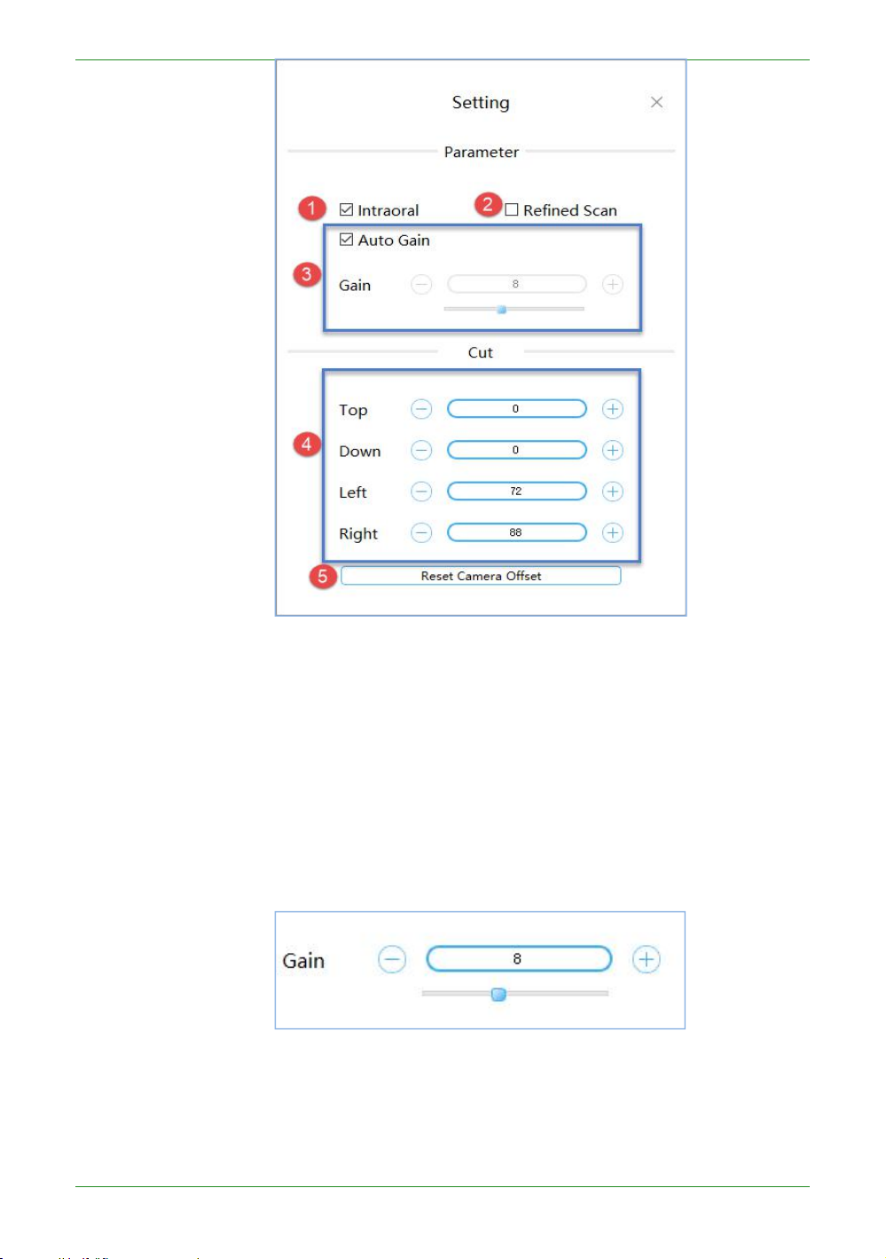
59
Intraoral Scanner User Manual
① Intraoral: The default check box is suitable for intraoral scan. It is
recommended not to check this box when scanning the dental model.
②Refined Scan: Unchecked by default. It is suitable for fine-grained areas to
③Auto Gain: The default is to adjust the gain automatically. If the “Auto Gain”
④ Cut: By default, it is read from the camera. You can also manually set the
select the range of repaired teeth, and the post-processing data processing is
more elaborate and enhances the data details.
check box is not checked, you can manually set the gain by dragging the slider or
entering a value.
Manually set the dental scan gain recommendation [0, 2];
Intraoral Scan gain is recommended to be 8.
cropping parameters of the top, bottom, left, and right sides of the camera

60
Intraoral Scanner User Manual
window.
⑤ Reset Camera Offset: Restores the cropping parameter values read in the
7
About: View the version number, the software dongle serial number, and the
8 Help: Open the user manual of the software;
9 Display device status icons during non-scanning:
Icon Example
Description
Connecting
Connected
Not connected
Connection error
Standby
Overheat
Sleeping mode
10
3D View: Displays the 3D model data acquired by the scan. Support the left mouse
11
The software supports the IMU operation, holding the scanner in a pen position to
camera.
number of days remaining for authorization;
During the scanning process, the number of scanning frames is displayed
here .
button to rotate the 3D model, and the right mouse button to translate the 3D model data.
maintain a horizontal still state, and perform the following actions:

61
Intraoral Scanner User Manual
When you push your wrist forward and downward, you can nod twice (swinging
about 45 degrees), which is equivalent to pressing the space bar on the keyboard,
The wrist drives the forearm to swing up and down two times at the same time
When the wrist is driven to swing the forearm to the left/right at the same time
At any time, the wrist rotates horizontally left/right two times to enter the IMU's
Wars the wrist forward and downward, keeping the scanner head down and at an
When the wrist moves the forearm to the center, keep the scanner head up and at
When the wrist moves the forearm to the left/right, keep the scanner head tilted
In the view rotation mode, the wrist drives the scanner to rotate slowly around the
In the view pan mode, the wrist drives the scanner to rotate slowly around the
and the software will start or pause the scanning operation;
(the swing amplitude is about 45 degrees), and the software will stop scanning or
complete the scanning operation;
(the swing amplitude is about 45 degrees), the software will perform the ReScan
operation. If there is a bullet box, the operation is used to switch the button
selection function.
view control mode and enter the IMU view control mode:
angle of more than 45 degrees with the horizontal plane for 0.5 seconds, the
software will perform the view reduction operation;
an angle of more than 45 degrees with the horizontal plane for 0.5 seconds, the
software will perform the view enlargement operation;
to one side and form an angle of 45 degrees or more with the horizontal plane for
0.5 seconds. The software will perform the view rotation/zoom mode switching
operation;
three spatial axes (keeping the angle between the scanner and the horizontal is
less than 30 degrees), so that the view model can be rotated synchronously. If the
model is to be rotated multiple times in one direction. The wrist can rotate the
model at a certain angle and then quickly return to the position (the view will not
respond at this time), and then slowly rotate in one direction to continue to rotate
the view model;
three spatial axes (keeping the angle between the scanner and the horizontal is
less than 30 degrees), so that the view model can be panned synchronously. If you
want to manipulate the model to translate multiple times in one direction. The
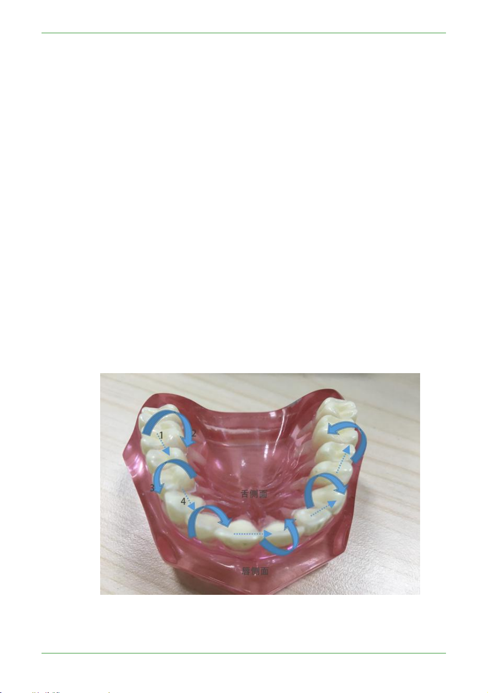
62
Intraoral Scanner User Manual
wrist can rotate the model at a certain angle and then quickly return to the
Keep the scanner level and stand still for 2 seconds to exit the IMU view operation
If the software starts scanning, it will automatically exit the IMU view operation
position (the view will not respond at this time), and then slowly rotate in one
direction to continue to pan the view model;
mode;
mode.
Introduction to IntraoralScan function
Scan technique
The scanning technique of the software has certain requirements. During the
scanning process, the speed cannot be too fast, and the model can be scanned to move
to the next part to scan. During the scanning process, when scanning the previous area,
the next area, the back side, and the front side, there must be a certain overlap area,
otherwise the scanned model may have accumulated errors.
The scanner adopts S-type scanning, and the following figure a is taken as an example.
The left distal tooth is used as the scanning starting tooth position (1 in the figure) and
the S-shaped scanning is performed in the direction of the dotted arrow.
The S-scan process is: face (1) -> lip side to tongue side (2) -> tongue side to lip side (3)
Figure a-scanning
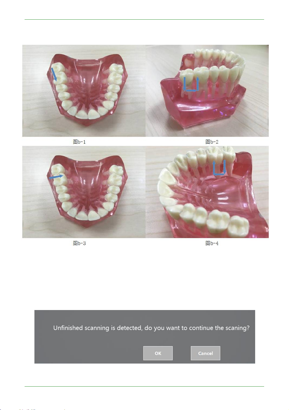
63
Intraoral Scanner User Manual
-> face (4). In Figure a, steps 1, 2, and 3 are performed as shown in Figure b below for a
single S-scan:
Loading project
Load the unscanned order (that is, the post-processing is not completed), open Intraoral Scan
pop-up message:
Click "OK" to continue the last scan and the full jaw data must be rescanned. Click Cancel to
restart scanning. After loading and processing the completed order, open Intraoral Scan pop-
Figure b-S-type scanning
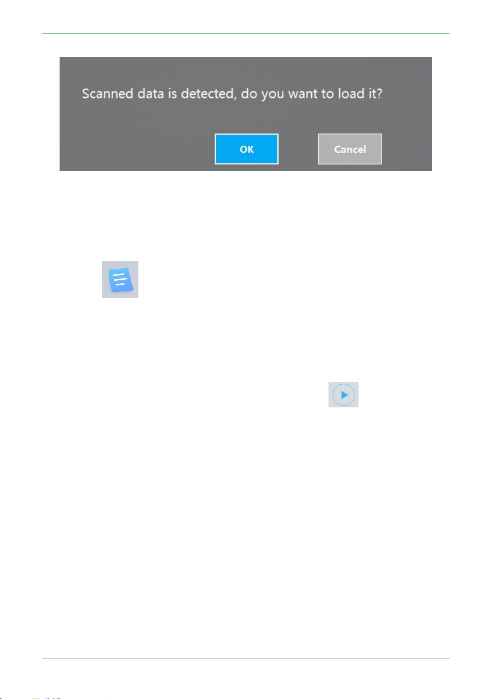
64
Intraoral Scanner User Manual
up message:
Click "OK" to load the data that was last processed. Click Cancel to restart scanning.
Dental Order System
Click the icon to return to the dental order system and view/create/edit the order.
Scan Upper/Lower Jaw
Scan
To enter the jaws scanning process, first check whether the image display in the image
window is normal. After confirming the normal, click the button or the space bar to
start scanning.

65
Intraoral Scanner User Manual
Figure 1 - Scanning process to support edge sweep optimization

66
Intraoral Scanner User Manual
Figure 2 - Scan pause, hole area is indicated by green
Pause
During the scanning process, you can click the or space bar to pause the scanning,
and delete the buccal and lingual data in the mouth during the pause to facilitate the user to
check the tooth sweeping situation. Click again to continue scanning.
Rescan
If the scan data is not satisfactory, you can re-scan it. Click the button to pop up a
prompt message box.

67
Intraoral Scanner User Manual
Select "Yes" to delete the previous data and restart the scan.
Add Scanning
After the scan or post-processing is completed, do not exit scan software interface and
click scan button to re-scan the data.
Scanning Completed
After confirming that the model scan is completed, click the Finish button or long
press the space bar to save. The green icon in the upper right corner of the icon as shown
below indicates that the scanning process is finished.

68
Intraoral Scanner User Manual
If the scan returns to the Dental Manager Pro or uploads the order, the prompt box
"Do you want to confirm the scan completed?" is displayed.
If you select "Yes", this order can no longer add scanning.
Note: The maximum number of frames for the upper/lower jaw scan is 3,000 frames.
When scanning to 2,500 frames, it will prompt whether to stop scanning or continue to
scan 500 frames.
Figure 3 - Scan completed

69
Intraoral Scanner User Manual
Scan Upper Jaw/Lower Jaw Implant
Create an order to define the type of dental restoration as the type of planting. The
scanning process has increased the process of scanning the implant.
Scan the lower jaw first (without Intraoral Scan bar). After the lower jaw scan is
complete, directly enter the scanning lower jaw implant interface and select the implant
area and delete.

70
Intraoral Scanner User Manual
Figure 1 - Selecting the implant area

71
Intraoral Scanner User Manual
Figure 2 - Delete
Click the button to enter the scanning implant process (must bring the
planting rod before scanning).

72
Intraoral Scanner User Manual
Figure 3- Scanning planting rod
Scan Total Jaw
After the lower jaw scan is completed and saved, it automatically proceeds to the next
Figure 4 - Post-processed implant data

73
Intraoral Scanner User Manual
scanning process, such as the full jaw scanning procedure. The whole jaw does not need to
scan the entire model, and supports scanning a whole jaw such as the anterior portion, two
full jaws on the left and right sides (recommended), three full jaws on the left and right sides
and the anterior teeth, so that the upper and lower jaw models of the scan are made. You
can stop scanning after connecting. The maximum number of frames in the whole jaw is 800
frames. Scanning to 300 frames will prompt whether to stop scanning or continue to scan
500 frames.
An example of scanning a full jaw: the purple on the left is the data of the full jaw of the
scan, and the tan is the result of the upper and lower jaws.
Scan a two-piece full jaw example (scan->pause, scan one piece of full jaw data once):
the left image shows the full jaw data of the left side of the scan, and the right image shows
the full jaw data of the left and right sides. .
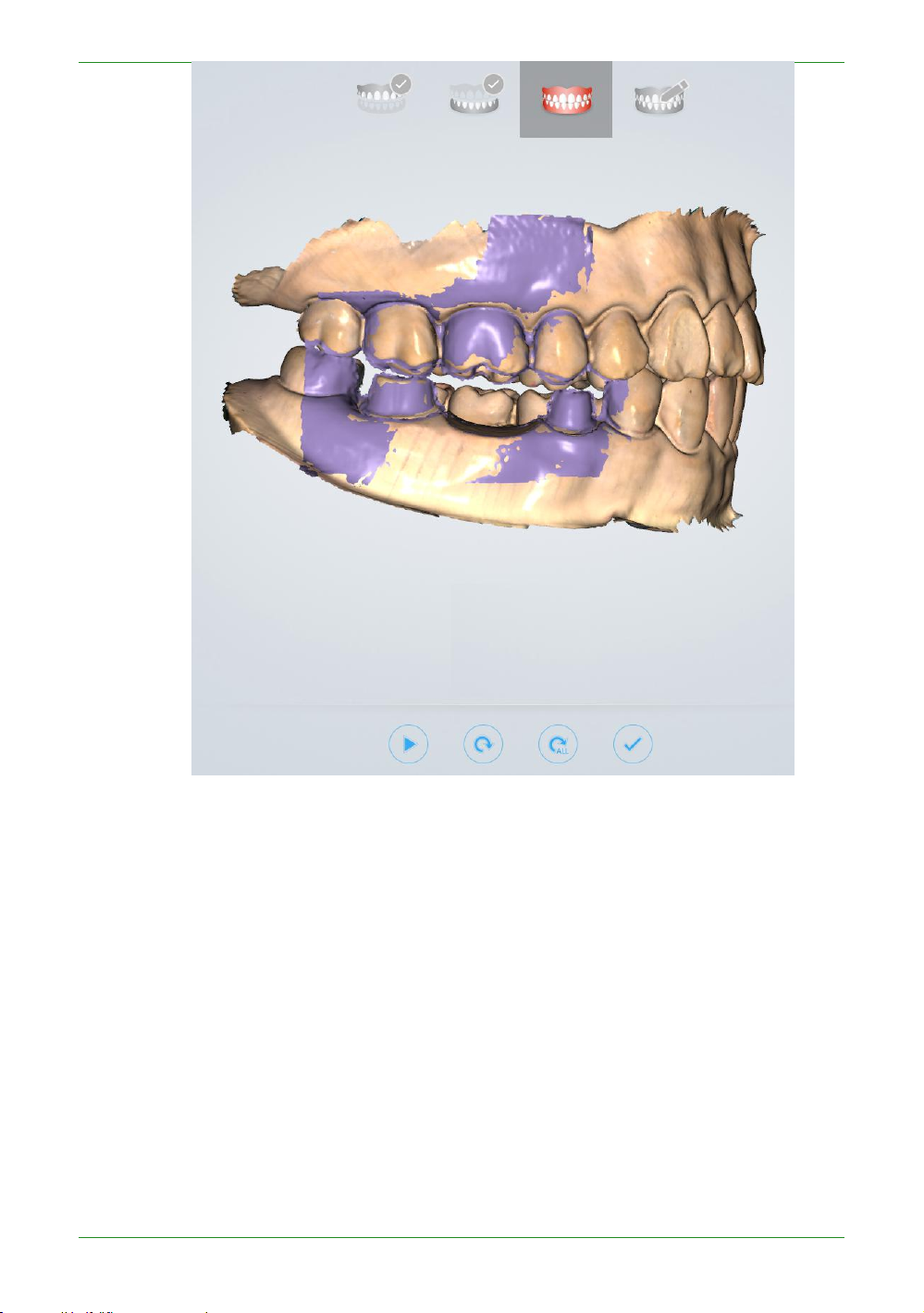
74
Intraoral Scanner User Manual
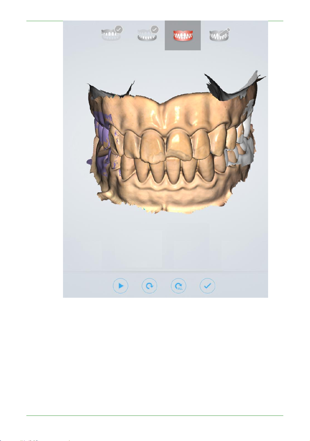
75
Intraoral Scanner User Manual
Scan a three-piece full jaw example:

76
Intraoral Scanner User Manual
Stitching effect after software post-processing: texture effect and non-texture effect
map:
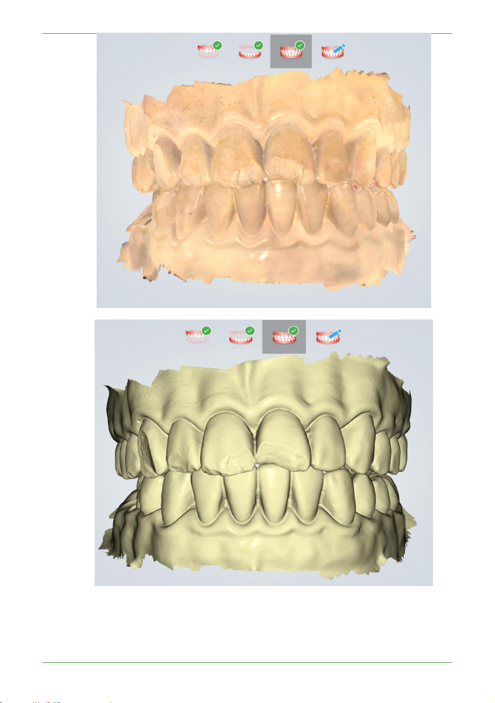
77
Intraoral Scanner User Manual
Pre-design
Scanning data is added to the design software in order to make it easier to use in the
design software. Users can skip this process and upload orders directly. This process has
five functions:
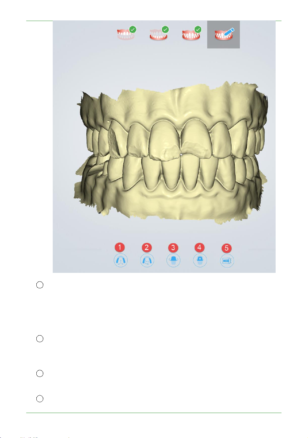
78
Intraoral Scanner User Manual
1
Adjust Coordinate: used to (manually) adjust the reference coordinate system of the
dental jaw, and adjust the dental jaw data to the unified standard reference coordinate system
2
Mark Teeth: used to manually mark the corresponding position of the tooth specified
3 Extract Margin line: used to extract and save the Margin line of the marked
4
Check Undercut: Used to calculate and view the undercut area of the marked
(supporting the ExoCAD coordinate system) (the middle of the upper and lower incisors is the
coordinate center, X outward (pointing to the observer), Y to the right (observer's perspective),
positive on the Z-axis, forming the right-handed coordinate system);
in the order in the scanning model for subsequent extraction of the Margin line and viewing
the undercut;
(corresponding) teeth;
(corresponding to the order) teeth.
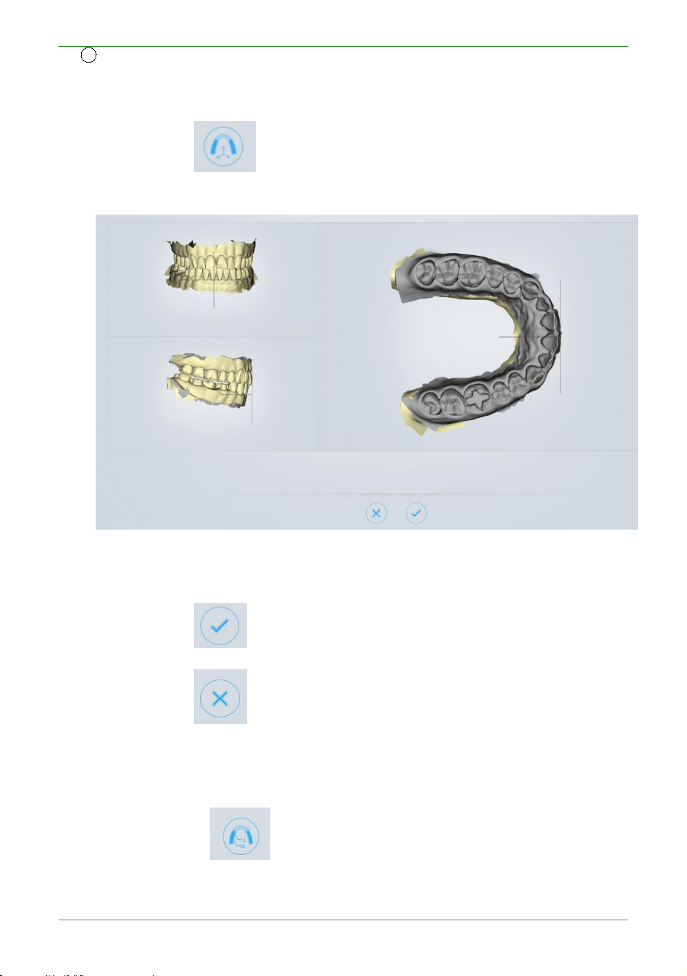
79
Intraoral Scanner User Manual
5
Check Bite: used to adjust and view the occlusal space of the upper and lower jaws;
Adjust Coordinate
Click the button under the "pre-design" process to enter the coordinate
position interface of the adjustment data, as shown below:
Rotate the data with the left mouse button and right-click the data to adjust the
position of the jaw.
Click the button to confirm and save the current adjustment result.
Click the button to cancel and discard the current adjustment result, and exit
the adjustment coordinate process.
Mark Teeth
Click on the button under the "Pre-design" process to enter the marker tooth
position interface, and the tooth map on the left side shows the teeth defined by the order.

80
Intraoral Scanner User Manual
Mark teeth operation: Select the tooth position to be marked in the tooth map, and
then double-click the data corresponding tooth position to mark the tooth position
information.
Click the Finish Teeth Marking button to confirm and save the current tag.
Click the Cancel Teeth Marking button to cancel and discard the current marker,
and exit the marker toothing process.
Extract Margin line
Click the button under the “Pre-design” flow to enter the extract margin line
interface.
Double-click on a Margin line of a tooth to select four points, the system automatically
draws the Margin line of the tooth.
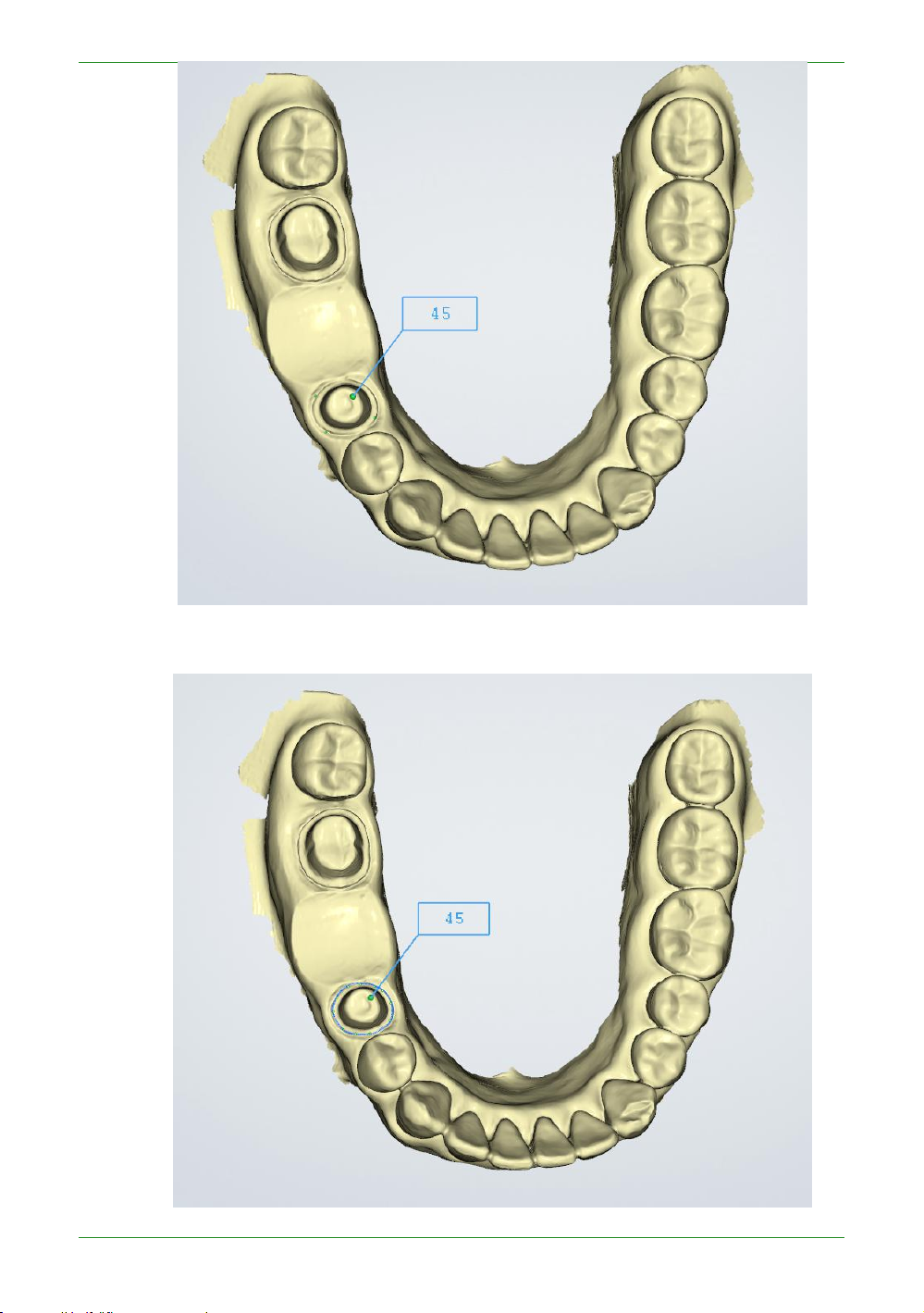
81
Intraoral Scanner User Manual
Figure 1 - Double click to select four points
Figure 2 - Automatically drawing the Margin line

82
Intraoral Scanner User Manual
Margin line editing operation: double-click to add a node; select a node, the node color
turns green to yellow, you can move or delete (right mouse click double click or press Del
key or ) this node.
Click the " " button to extract the Margin line of the next tooth. Finally click
" " to complete the extraction of all Margin line, and generate a "45-margin.xyz"
Margin line file in the order directory.
Description of several operation buttons:
: Previous Tooth switches to the last marked tooth and its Margin line.
: Next Tooth switches to the next marked tooth and its Margin line.
: Delete Delete a node if some node on the Margin line is selected. If no node
is selected, the Margin line of the current tooth is deleted.
: Cancel And Exit abandon the extracted Margin line and exit the process of
extracting the Margin line.
: Finish And Save confirms and saves the extracted Margin line and exits the
extract Margin line process.
Check Undercut
Click the button under the “Pre-design” flow to enter the inverted interface.
The following figure shows the effect of the undercut display in different visual directions:
the blue arrow indicates the visual direction, and the blue surface of the tooth indicates the

83
Intraoral Scanner User Manual
undercut area.

84
Intraoral Scanner User Manual
Undercut operation: Double click or click button to adjust the undercut angle.
Description of several operation buttons:
or : Swap Jaws for upper and lower jaw switching
: Generate Undercut shows the undercut effect.
: Finish Undercut exit the undercut process.
Check Bite
Click the button under the “Pre-design” process to enter the check bite interface.
Green indicates the distant area of the two jaw teeth, red indicates the collision area of the
two jaw teeth, and blue indicates the bite area of the two jaw teeth.

85
Intraoral Scanner User Manual
Figure 1 - Two jaw tile effect

86
Intraoral Scanner User Manual
Description of several operation buttons:
:Open/Close Jaws switches between the two jaws and the bite effect.
:Occlusal Adjust adjusts the bite.
; Cancel And Exit gave up the adjusted bite relationship and exited the test bite
process.
: Finish And Save saves the adjusted snap closure and exits the detection bite
process.
Upload Order
Figure 2 - Two jaw bite effect picture
When uploading the order for the first time in Intraoral Scan, it will prompt “You have
not logged in to the account. Whether to direct to the setting interface to log in?”, select
“Yes” to open the “Configure Account” interface. See the "Upload Order" introduction of the

87
Intraoral Scanner User Manual
Dental Manager Pro for details.

88
Intraoral Scanner User Manual
CHAPTER
CHAPTER
8 Using Dental Cloud
Introduction to Dental Cloud
Dental Cloud is a platform for connecting clinical and technical
workers. In this platform, you can establish relationships with labs,
doctors/clinics, and doctor users; you can manage order cases;
manage organizations and maintain account information.
Visit the website: http://dental.shining3d.com
Register Account
To register for the dental cloud account, click the “Register” link to
go to the dental cloud website to register. It is recommended to
open the dental cloud website using browsers such as Chrome,
Firefox, and Apple.
Click "Login" in the top right corner of the homepage to open the
login page.

89
Intraoral Scanner User Manual
"Registration / Application", select the registration type.
I am a hospital/clinic: a registered hospital/clinic institution and administrator.
I am a doctor: Register an individual user. You can log in directly after registration.
I am a lab: registered dental laboratory and administrators. After registration is
After registration is successful, you need to wait for the system administrator to
review before you can log in.
successful, you need to wait for the system administrator to review before you can
log in. Note that this type of account can only be used on the web side and cannot
be used on the desktop client.
Fill in the real application information according to each content (the notification of
information such as the relationship network and order status will be sent to the mobile
phone number and email address to be filled in)
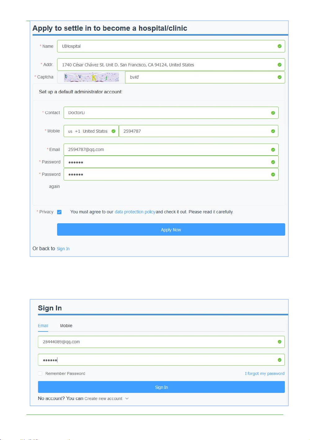
90
Intraoral Scanner User Manual
After the registration is successful, the page automatically jumps to the login interface,
enter the correct mailbox or mobile phone number and password, you can set the
remember password to facilitate subsequent quick login.
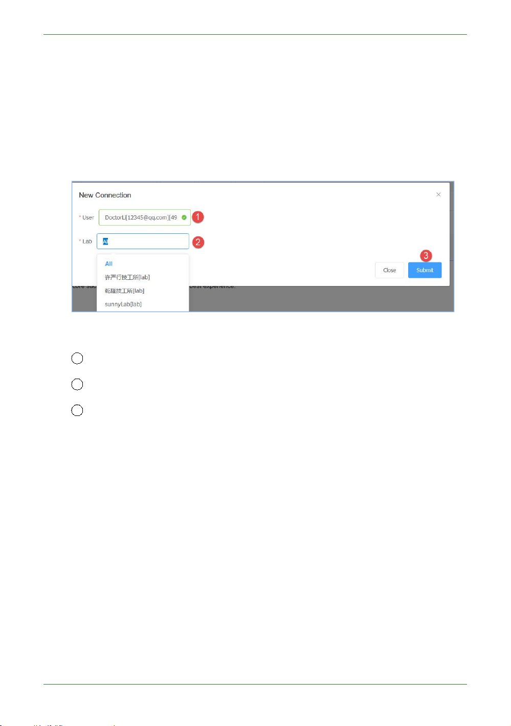
91
Intraoral Scanner User Manual
After the login is successful, the hospital, clinic or doctor's account can establish a network
1 User: Select the user himself
2
Lab: Select a cooperative from the drop-down list
3
Submit: Submit the newly created network.
connection with the partner technical institution (ie add the lab)
Establish a relationship network
The network can only be created by a doctor/hospital/clinic account and then accepted
or rejected by the lab. The doctor can only upload the order data to the accepted
laboratories. After logging in to the hospital, clinic or doctor account, select “Relational
Network” in the upper right corner of the interface to create a new network.
The submission is successful and is displayed in the page list. The relationship status of
the newly created relationship is “to be confirmed”. You need to wait for the lab to accept
the confirmation (the relationship status is "active"), and only the relationship confirmed by
the lab can upload the data.
Management institution
An organization administrator can add/remove members for this organization.
Add member
After logging in, "Admins" ->"Members", create a new administrator and ordinary
members for the organization.

92
Intraoral Scanner User Manual
1
Belongs: Select the name of the institution.
2
Nick Name: member nickname.
3
Mobile: The mobile number of this member is also the account that the mobile
phone logs in. The default password for login is 888888. Mobile phone and mailbox,
4
E-mail: This member's e-mail is also the account that the e-mail is logged in. The
5
Is Admin: Set whether it is an administrator. The default is No.
6 Submit: Fill in the information and submit the member successfully.
you can choose one of the two.
default password for login is 888888.
Delete member
Select the member you want to delete and click the "Delete" button to confirm the
deletion.
Management cases
The account is successfully logged in. Select “Case” in the upper right corner of the page to
list all the use cases managed by this user.
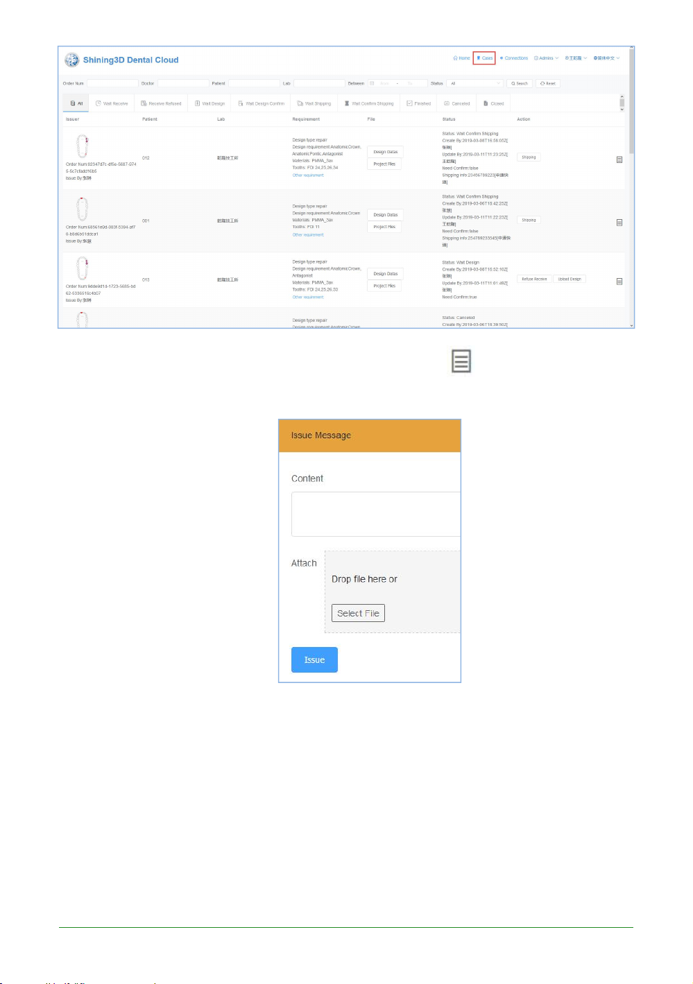
93
Intraoral Scanner User Manual
Each order doctor and lab can instantly communicate, click , expand the
communication box, and publish information or documents on the web page.
Order status process
The order is transferred between the hospital (clinic/doctor) and the laboratories, and
the two parties cooperate to advance the entire process from one visit to completion of
treatment. The doctor operates in the client Dental Manager Pro, and the lab operates on
the web page side. The most common flow chart for uploaded order status is as follows:
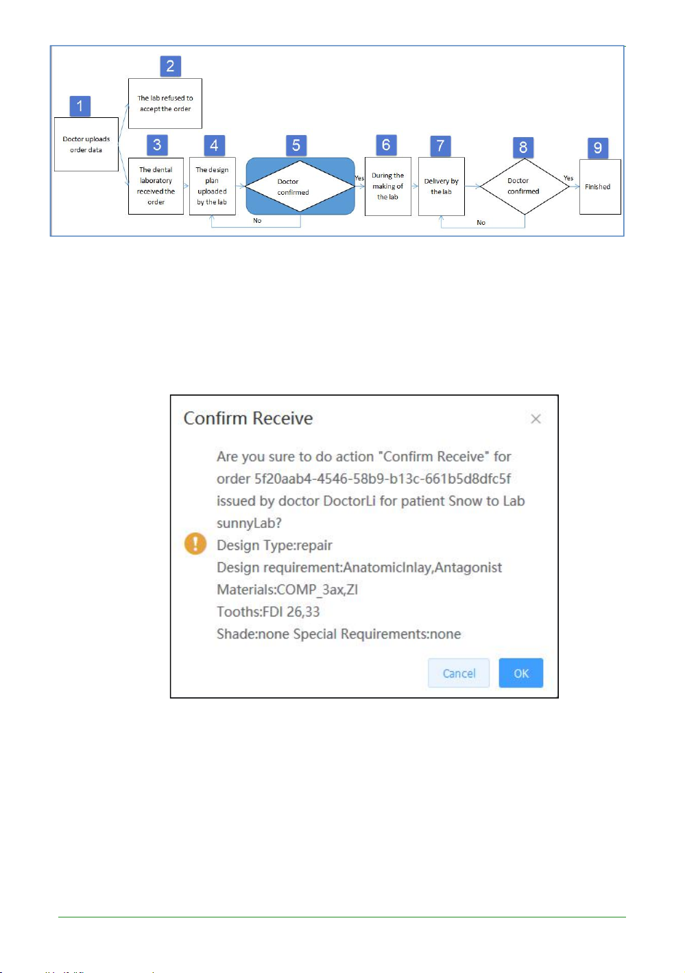
94
Intraoral Scanner User Manual
Brief introduction to the flow chart:
1) Doctor uploads order data: see the previous section for details.
2) The lab refused to accept the order: the lab of the lab refused to accept the order.
3) The lab received the order: the lab of the lab confirmed the order.
4) The design plan uploaded by the lab: the lab of the lab uploads the design plan,
including the documents and data.
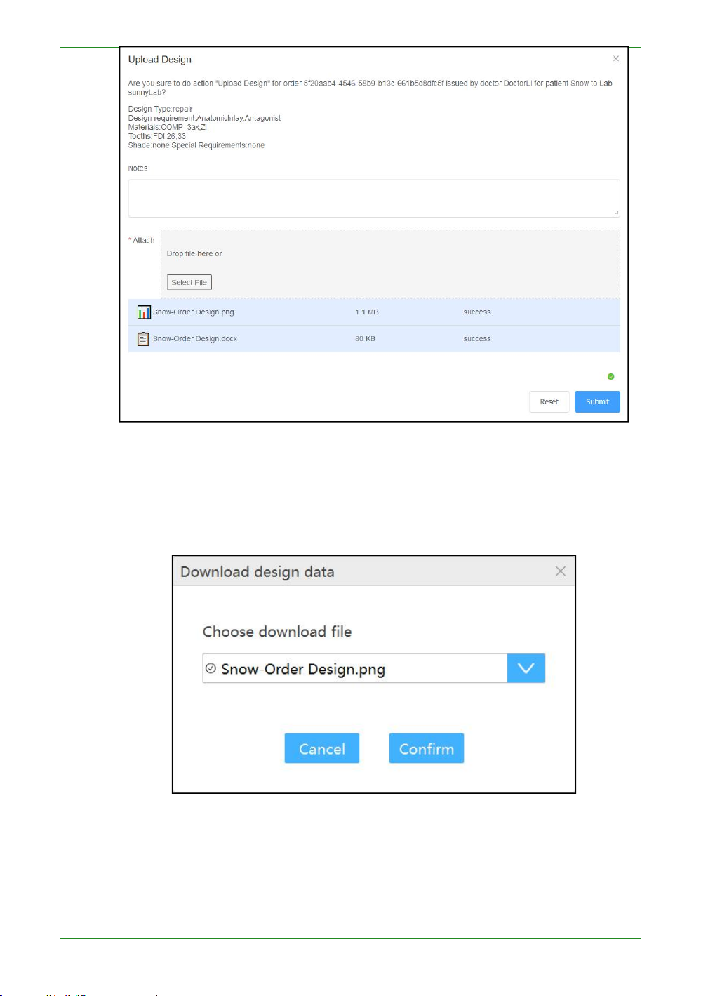
95
Intraoral Scanner User Manual
Select the file to be uploaded, wait for the file to be uploaded successfully, and submit.
5) Doctor confirmed plan: After the lab uploads the design plan, the order status is
“Need Conirm Design”, and the doctor can download the design plan in the client
Dental Manager Pro.
The design data is saved by default in the DesignData folder of the order catalog. If
the design plan is approved, the doctor “confirm Design” and the order status is
“Making”; if not, the doctor “Request Re-design”, fills in the design requirements, and
the order status is “Accepcted”, which requires the lab to redesign the plan , upload,
doctor confirm again.

96
Intraoral Scanner User Manual
If the doctor chooses not to review the design when uploading data, skip this process.
6) During the making of the lab: After the doctor confirms the design plan, the order
status is “Making”, indicating the processing data of the lab.
7) Delivery by the lab: The data processing of the lab's office is completed, and the
logistics information is submitted and delivered. The order status is "Delivering".
8) Doctor confirmed the receipt: After the lab delivers the goods, the doctor can view
the logistics information, and confirm the receipt after receiving the goods. The order
status is “Finished”. If the doctor does not receive the goods or the goods have
problems, request re-delivery, the order status is "Wait Shipping", the lab needs to redelivery, the doctor confirms the receipt again.
9) Finished: This order process ends.

97
CHAPTER
9 Care and maintenance
Pre-cleaning, disinfection, and sterilization
The whole set of Aoralscan 2 , including scanner tip, scanner
body, and scanner cradle, requires proper care, cleaning, and
handling. As individual part may be processed differently, read
and follow the information and instructions given to help you
effectively and thoroughly reprocess the set.
We suggest that you reprocess the Aoralscan 2 in the following
order:
1. Scanner cradle care
2. Scanner body care
3. Scanner tip care
WARNINGS
• All parts are shipped non-sterilized. Follow the
instructions prior to initial use.
• Ensure you have completely disconnected the
power supply and all connections from the scanner.
• Follow the instructions given in this User Manual to
pre-clean, disinfect, and sterilize each part of the
scanner. Using other methods not approved by
Shining3DCorporation will damage your scanner
and void your warranty.
• Using detergent, disinfection solutions or wipes,
sterilization procedures other than those specified
in this User Manual may damage the product and
void your warranty.
• Only sterilize the part(s) for which a sterilization
method is specified. Do not attempt to sterilize all
parts of the product. Shining3DCorporation is not
liable for any damages due to improper sterilization.

98
Intraoral ScannerUser Manual
• After sterilization, wait until each of the parts is at room temperature to
CAUTION
Avoid using detergent of any kind as some detergents or surfactants might
prevent possible heat injuries to the user and the patient.
• To prevent cross-contamination, pre-cleaning, disinfection, and
sterilization must be correctly performed after EACH use.
• When the scanner tip is detached from the scanner, always protect the
subtle units and the inner optical components on the front end of the
scanner body by putting on the supplied protection cap.
Scanner cradle care
The scanner cradle requires an intermediate-level disinfection.
Disinfection
WARNINGS
• Concerning hand hygiene and personnel safety when performing precleaning and disinfection/sterilization, you must wear clean surgical
gloves before you start.
• Always ensure that you have pre-cleaned and disinfected/sterilized the
scanner body, scanner cradle, and scanner tip before each scan.
• The caring methods for the scanner cradle, scanner body, and scanner tip
are different and must be executed separately. After disinfecting the
scanner cradle, you may proceed with the scanner body and finally the
scanner tip. See Scanner body care on chapter 9 and Scanner tip care on
chapter 9 for details.
• Ensure that the scanner body is not placed in the cradle prior to
disinfecting the scanner cradle.
Follow the steps below to complete the disinfection:
1. Disconnect the power of the Aoralscan 2 (see Disconnecting the scanner on
chapter 4
2. Hold the cradle firmly with your hand.
3. Use new cotton gauze moistened with 70%-75% solution of ethanol to wipe the
penetrate into the surface of the cradle.
4. When done, store the cradle in a clean and safe place.
5. Proceed to the disinfection of the scanner body (see Scanner body care on
).
surface of cradle.
chapter 9).

99
Intraoral Scanner User Manual
Scanner body care
NOTE
Do not place your finger(s) on the mirror of the tip when detaching as this may
The scanner body requires an intermediate-level disinfection.
Disinfection
WARNINGS
• Concerning hand hygiene and personnel safety when performing precleaning and disinfection/sterilization, you must wear clean surgical
gloves before you start.
• Always ensure that you have pre-cleaned and disinfected/sterilized the
scanner body, scanner cradle, and scanner tip before each scan.
• The caring methods for the scanner cradle, scanner body, and scanner tip
are different and must be executed separately. Before disinfecting the
scanner body, you shall start with the cradle first. See Scanner cradle care
on chapter 9) for details.
• Ensure that the scanner tip is detached from the scanner, and the
protection cap is put on the scanner when disinfecting the scanner body.
Follow the steps below to complete the disinfection:
1. Disconnect the power of the Aoralscan 2 (see Disconnecting the scanner
on chapter 4
2. Hold the scanner tip firmly with your thumb and forefinger on both sides, and
then gently slide the tip off from the scanner, as illustrated.
).
result in damage to the mirror.
3. Store the detached tip in a safe place, e.g. a dental instrument tray, prior to
disinfecting the scanner body.
4. Hold the supplied protection cap with the triangle mark facing upward. Then,
align the protection cap blocks to the matching slots on the front end of the
scanner body.
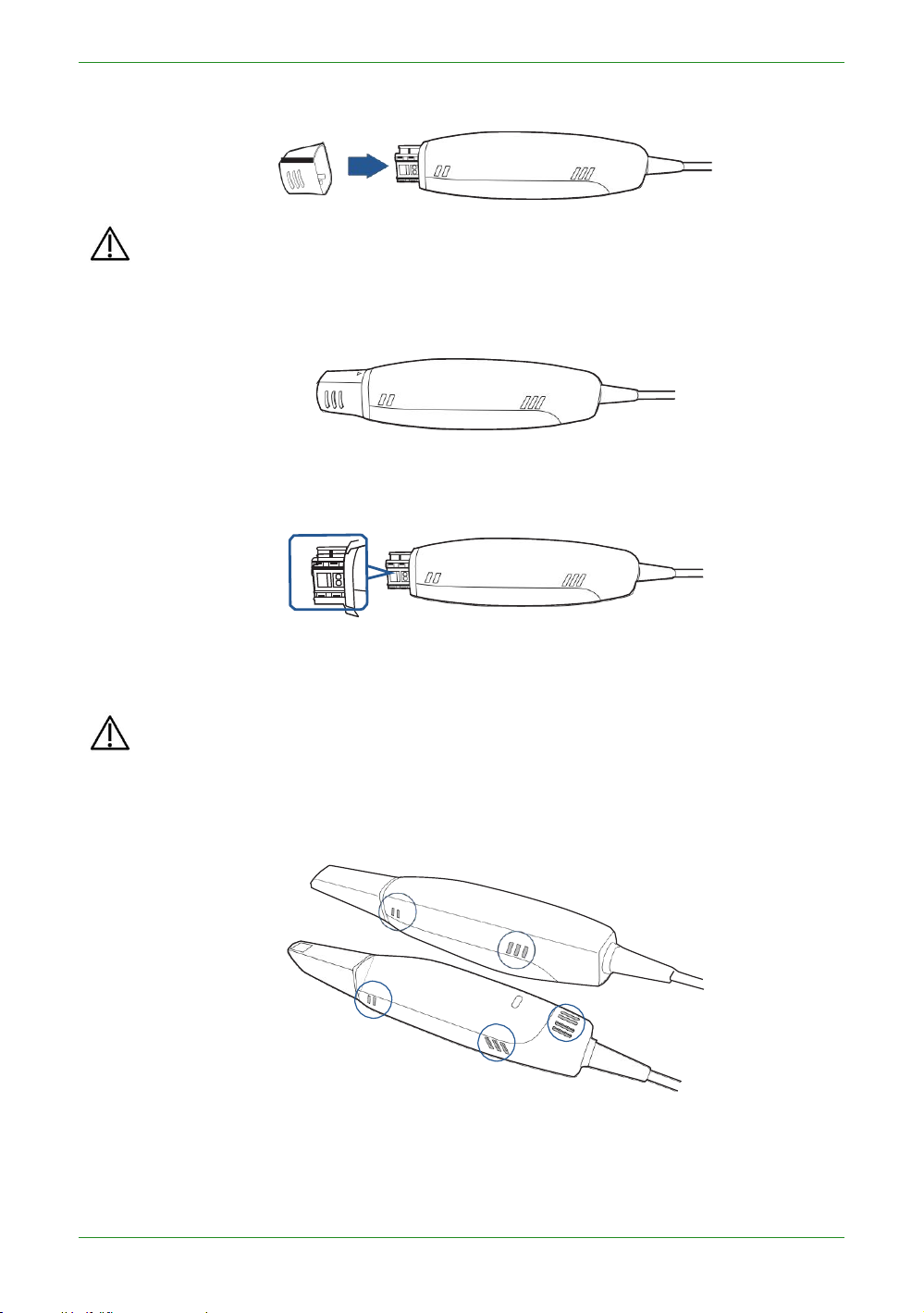
100
Intraoral ScannerUser Manual
5. Slide the protection cap onto the scanner to prevent damage and dust.
CAUTIONS
• When the scanner tip is detached, always protect the subtle units and the
inner optical components on the front end of the scanner by putting on the
supplied protection cap.
• Do not attempt to clean the outer units and inner optical components on
the front end of the scanner with any sharp objects or other such tools,
which may result in scratches and damage to the scanner.
6. Hold the scanner body with your hand.
7. Use new cotton gauze moistened with 70%-75% solution of ethanol to wipe the
surface of scanner body.
CAUTIONS
• Avoid using detergent of any kind as some detergents or surfactants might
penetrate into the surface of the scanner body.
• Do not clean the intake and exhaust vents with any sharp objects or other
such tools.
8. When done, store the scanner body in a clean and safe place.
9. Proceed to the cleaning, disinfection or sterilization of the scanner tip (see
Scanner tip care on chapter 9).
 Loading...