

Page 1

STM Series
Oil Heater
Date: Sep, 2018
Version: Ver.H (English)
Page 2

Page 3

Contents
1. General Description ......................................................................................7
1.1 Coding Principle ......................................................................................8
1.2 Feature ....................................................................................................8
1.3 Options ....................................................................................................8
1.4 Technical Specifications ........................................................................ 10
1.4.1 Specification ................................................................................ 10
1.4.2 Pump Performance ..................................................................... 10
1.4.3 Reference Formula of Mould Controllers Model Selection .......... 11
1.5 Safety Regulations ................................................................................ 11
1.5.1 Safety Signs and Labels ............................................................. 11
1.5.2 Signs and Labels ......................................................................... 13
1.5.3 Operation Regulations ................................................................ 14
1.5.4 Transportation and Storage of the Machine ................................ 14
1.6 Exemption Clause ................................................................................. 16
2. Structure Characteristics and Working Principle .................................... 17
2.1 Working Principle ................................................................................... 17
3. Installation and Debugging ........................................................................ 18
3.1 Installation Space .................................................................................. 18
3.2 Mould and Water Coupling .................................................................... 18
3.3 Power Supply ........................................................................................ 19
3.4 Options Installation ................................................................................ 19
3.4.1 Installation Steps for Options Water Manifold (Dewaxing) .......... 19
3.4.2 Installation Steps for Options Water Manifold (Welding) ............. 20
4. Operation Guide .......................................................................................... 21
4.1 Control Panel ......................................................................................... 21
4.2 Menu Introduction .................................................................................. 23
4.2.1 Main screen ................................................................................ 23
4.2.2 MENU Screen ............................................................................. 23
4.3 Parameter Table .................................................................................... 24
4.3.1 Parameter Setting Table ............................................................. 24
3(42)
Page 4

4.3.2 Output Setting ............................................................................. 27
4.3.3 Alarm Settings ............................................................................. 28
4.3.4 Startup for refilling ....................................................................... 29
4.3.5 Auto refilling process ................................................................... 29
4.4 Errors and Causes ................................................................................. 30
5. Trouble-shooting ........................................................................................ 31
6. Maintenance and Repair ............................................................................. 33
6.1 Open the Covers ................................................................................... 34
6.2 Y Type Strainer ...................................................................................... 35
6.3 Solenoid Valve ....................................................................................... 35
6.4 Pipe Heater............................................................................................ 36
6.5 Cooling Pipes ........................................................................................ 36
6.6 Printed Circuit Board ............................................................................. 38
6.7 Displayer Terminal Connecting Diagram ............................................... 40
6.8 Maintenance Schedule .......................................................................... 41
6.8.1 About the Machine ...................................................................... 41
6.8.2 Installation & Inspection .............................................................. 41
6.8.3 Daily Checking ............................................................................ 41
6.8.4 Weekly Checking ........................................................................ 41
6.8.5 Trimonthly Checking ................................................................... 41
6.8.6 Half-yearly Checking ................................................................... 41
6.8.7 Yearly Checking .......................................................................... 42
6.8.8 3 year Checking .......................................................................... 42
Table Index
Table 1-1: Specification ..................................................................................... 10
Table 4-2: Control Setting ................................................................................. 24
Table 4-3: Alarm Setup ..................................................................................... 24
Table 4-4: Output Setting .................................................................................. 24
Table 4-5: Temp. Setting ................................................................................... 25
Table 4-6: Time Setting ..................................................................................... 25
Table 4-7: One Week ON/OFF Setup ............................................................... 25
4(42)
Page 5

Table 4-8: Communication Setup ...................................................................... 26
Table 4-9: Instrument Setup .............................................................................. 26
Table 4-10: Refilling Setup ................................................................................ 26
Picture Index
Picture 1-1: Pump Performance ........................................................................ 10
Picture 2-1: Working Principle ........................................................................... 17
Picture 3-1: Installation Space........................................................................... 18
Picture 3-2: Mould and Water Coupling 1 ......................................................... 18
Picture 3-3: Mould and Water Coupling 2 ......................................................... 19
Picture 4-1: Control Panel ................................................................................. 21
Picture 4-2: Main Menu Screen ......................................................................... 23
Picture 4-3: MENU Screen ................................................................................ 23
Picture 6-1: Open the Covers 1 ......................................................................... 34
Picture 6-2: Open the Covers 2 ......................................................................... 34
Picture 6-3: Open the Covers 3 ......................................................................... 34
Picture 6-4: Y Type Strainer .............................................................................. 35
Picture 6-5: Solenoid Valve ............................................................................... 35
Picture 6-6: Pipe Heater 1 ................................................................................. 36
Picture 6-7: Pipe Heater 2 ................................................................................. 36
Picture 6-8: Cooling Pipes 1 .............................................................................. 37
Picture 6-9: Cooling Pipes 2 .............................................................................. 37
5(42)
Page 6

6(42)
Page 7
1. General Description
Read this manual carefully before operation to prevent damage of the
machine or personal injuries.
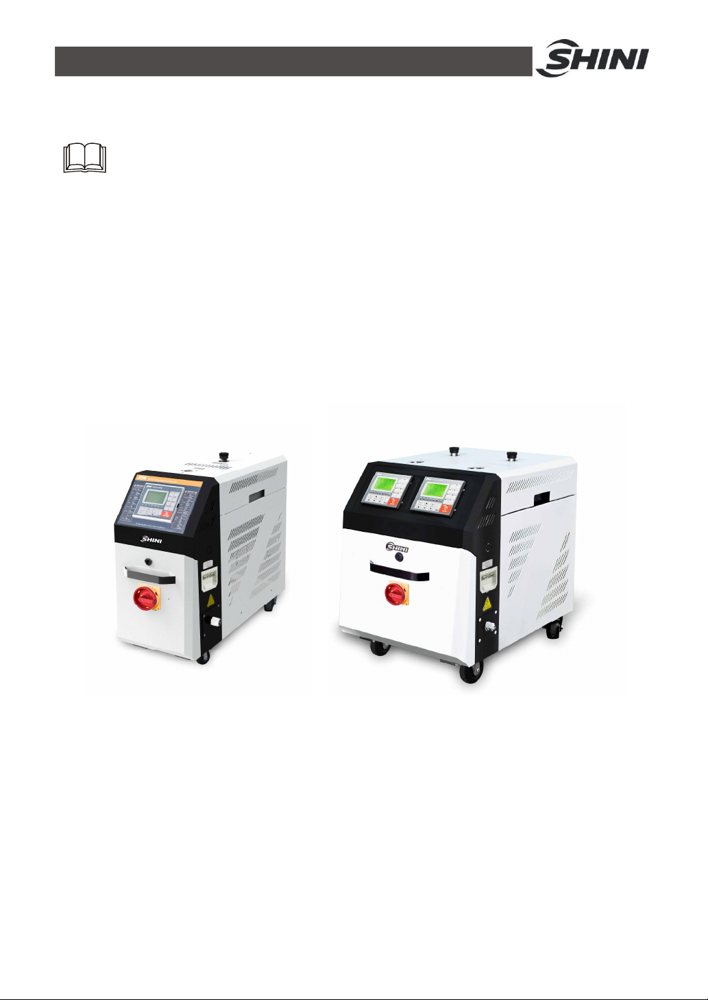
The STM-O series standard oil heater are used to heat up the mould and maintain
this temperature, although they can be used in other similar applications. High
temperature oil from the mould is returned to the cooling tank and cooled by
indirect cooling. It is then pressurised by the high-pressure pump, sent to the
heating tank and finally to the mould with a constant temperature. With our
optimised design, oil can reach a maximum of 200℃ and the HANYOUNG
temperature controller can maintain an accuracy of ±1℃.
Model: STM-910 Model: STM-910D
7(42)
Page 8
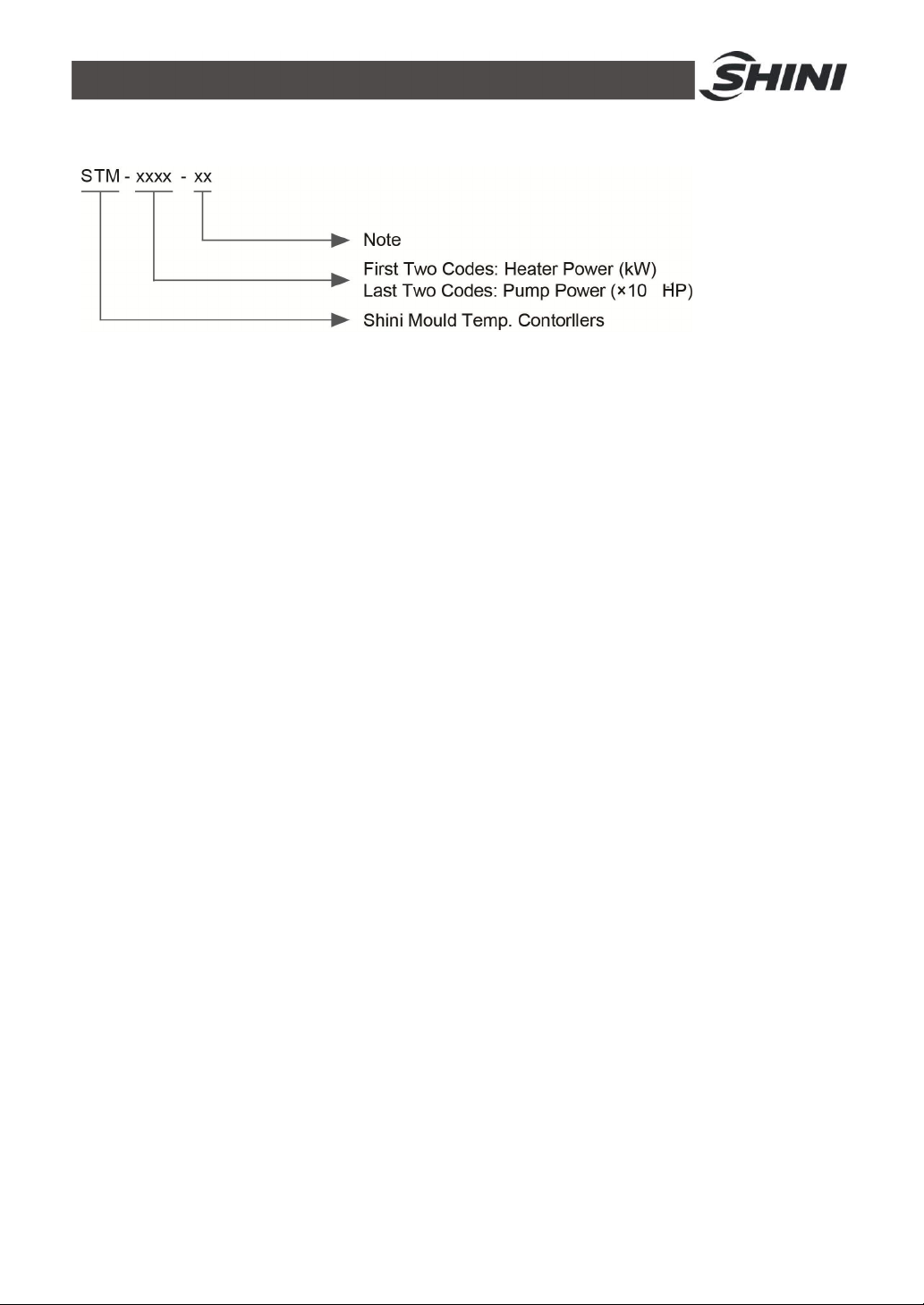
1.1 Coding Principle
1.2 Feature
l Controller adopts 3.2" LCD for easy operation.
l Equipped with the design of 7-day automatic start/stop timer. LCD screen
can be converted between Chinese and English. The unit of temperature
can be converted between oF and ℃.
l P.I.D multi-stage temperature control system can maintain mould
temperature with accuracy of ±0.5℃.
l Adopts high efficiency high temperature pump, which can meet the
demands of temperature control for precise moulds and mould loop with
minor diameter to achieve precise temperature control and high efficient
heat exchange.
l Multiple safety devices including power reverse phase protection, pump
overload protection, overheat protection and low level protection that can
automatically detect abnormal performance and indicate this via visible
alarm.
l Pipe heater are made of stainless steel.
l For standard STM-O, the heating temperature can reach 200℃,while for
STM-HT, it can reach 300℃.
l STM-HT is equipped with magnetic pump and its internal structure is
made of high pressure resistance stainless steel to prevent any explosion.
l Adopted Ethernet communication function to realize central monitoring
online.
1.3 Options
l Water manifolds, Teflon hose and Transfer oil are optional.
l Displays of mold temperature and return oil temperature of mold are
optional.
8(42)
Page 9

l Buzzer is optional .Add “B”at the model behind.
l Magnepic Pump (Excluded for STM-3650 and STM-D models),add "M" at
the end of the model code.
l It could option with magnetic filter to prolong service life of magnetic pump
(only suitable for models with magnetic pump). Add “MF” at the end of the
model code.
All service work should be carried out by a person with technical training or
corresponding professional experience. The manual contains instructions for both
handling and servicing. Chapter 6, which contains service instructions intended for
service engineers. Other chapters contain instructions for the daily operator.
Any modifications of the machine must be approved by SHINI in order to avoid
personal injury and damage to machine. We shall not be liable for any damage
caused by unauthorized change of the machine.
Our company provides excellent after-sales service. Should you have any
problem during using the machine, please contact the company or the local
vendor.
Headquarter and Taipei factory:
Tel: (886) 2 2680 9119
Shini Plastics Technologies (Dongguan), Inc:
Tel: (86) 769 8111 6600
Shini Plastics Technologies India Pvt.Ltd.:
Tel: (91) 250 3021 166
9(42)
Page 10
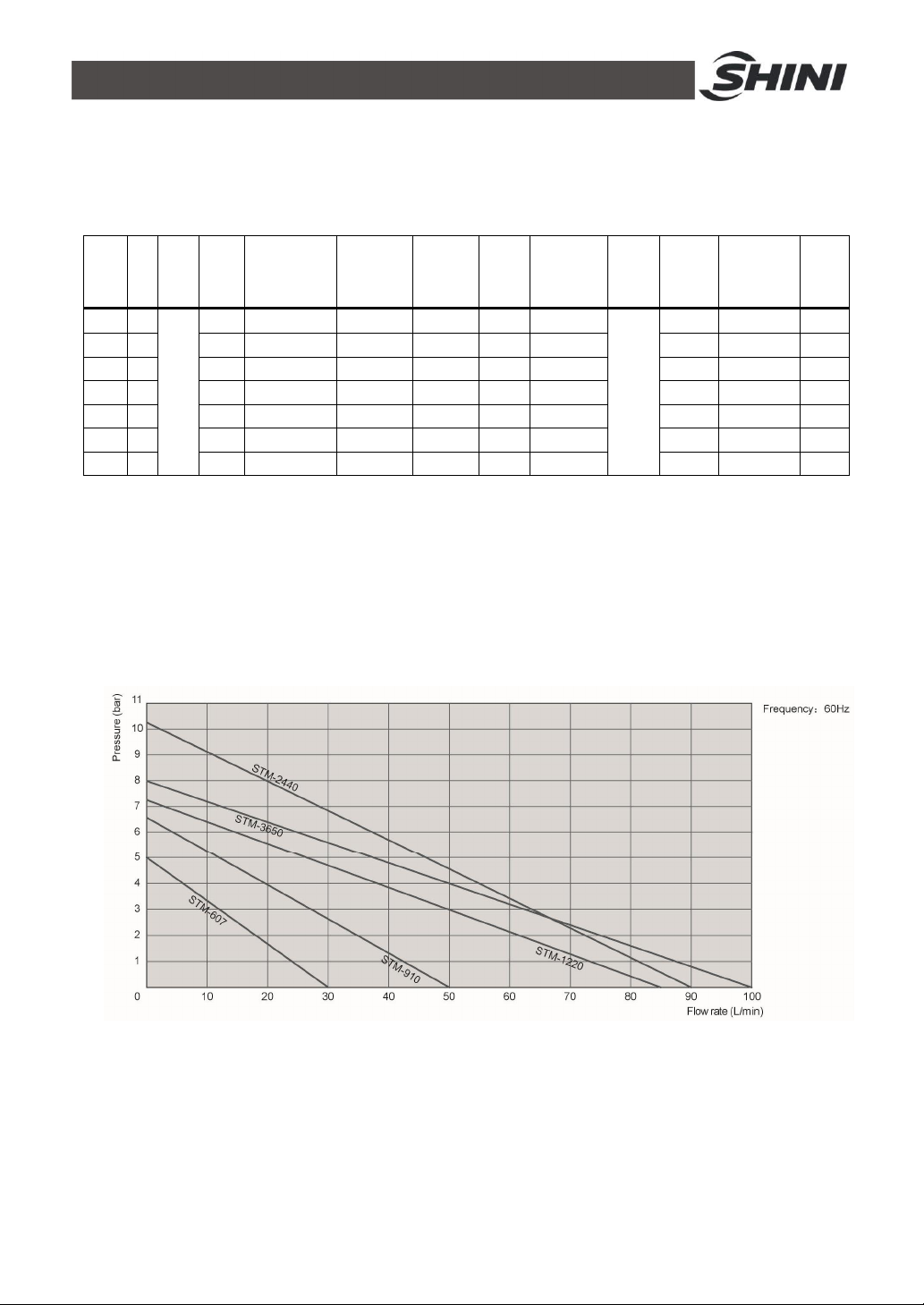
1.4 Technical Specifications
Max. pump
Cooling
Weight
1.4.1 Specification
Table 1-1: Specification
Pipe
Model
Ver.
STM-
607 H
607D G
910 G
910D G
1220 F
2440 E
3650 E
Max.
Temp.
200℃
Pump Power
Heater
(kW)
6 0.55 / 0.63 27 / 30 3.8 / 5 1 6 / 3.2
6×2 0.55×2 27×2 3.8 2 6×2 / 3.2×2
9 0.75 / 0.92 42 / 50 5.0 / 6.4 1 6 / 3.2 3/4 / 3/4 700x350x900 70
9×2 0.75×2 / 0.92×2 42×2 / 50×2 5.0 / 6.4 2 6×2 / 3.2×2
12 1.5 / 1.9 74 / 84 6.2 / 7.2 1 6.8 / 11.8 1 / 1 755x320x900 100
24 2.8 / 3.4 90/ 90 8.0 / 10.2 2 11 / 16 1 / 1 899x407x1009 145
36 4.0 / 4.0 100 / 100 8.0 / 8.0 3 14 / 16 11/4 / 11/
(kW)
(50 / 60Hz)
Note: 1) "D" stands for dual-heating zones. We reserve the right to change
2) Pump testing standard: Power of 50 / 60Hz, specifications without prior notice.
purified water at 20. ( There is ±10% toleranc℃ e
for either max. flowrate or max. pressure ).
3) "*" Stands for options.
4) When machine works continously,the suggested temperature should not higher than 180℃.
5) Power supply: 3Φ, 230 / 400 / 460 / 575VAC, 50 / 60Hz.
Max. pump
Flow(L / min)
(50 / 60Hz)
Pressure
(bar)
(50 / 60Hz)
Heating
Tank
Number
Main / Sub.
Oil Tank (L)
Method
Indirect
Inlet
(inch)
4
Dimensions
(mm)
(H×W×D)
928x407x999 155
(kg)
/Outlet
3/4 / 3/4 700x350x900 70
3/4 / 3/4 700x535x900 120
3/4 / 3/4 700x535x900 140
1.4.2 Pump Performance
Picture 1-1: Pump Performance
10(42)
Page 11
1.4.3 Reference Formula of Mould Controllers Model Selection
Heater Power (kW) = mould weight (kg) × mould specific heat (kcal/kg℃) ×
temperature difference between mould and environment (℃) × safety coefficient /
heating duration / 860
Note: safety coefficient can select a value from 1.3 to 1.5.
Flow Rate (L/min) = heater power (kw) × 860 / [heating medium specific (kcal/kg℃)
× heating medium density (kg/L)×in/outlet temperature difference (℃)× time (60)]
Note: Water specific heat =1kcal/kg℃
Heating medium oil specific heat =0.49kcal/kg℃
Water density =1kg/L
Heating medium oil density =0.842kg/L
1.5 Safety Regulations
Strictly abide by the following safety regulations to prevent damage of the machine
or personal injuries.
1.5.1 Safety Signs and Labels
Danger!
The unit is designed to endure high temp, and high pressure. For safe
operation, do not remove the covers or switches.
Attention!
The unit should be operated by qualified personnel only.
During operation, avoid wearing gloves or clothes that may cause danger.
Turn off main switch when power supply is off.
Stop the unit when there may be power supply problems caused by static
electricity.
Put on safety gloves and shoes during installation or relocation.
Components from our company can only be used for replacement.
Warning!
11(42)
Page 12
Do not touch the switch with wet object or hands.
Do not use the machine before fully aware of its performance.
Be careful not to touch or hit the switch or sensor.
Please keep enough operation space, and keep away obstacles.
To avoid producing statics, clean the floor from oil or water to keep a dry
environment.
Protect the machine against severe vibration or collision.
Do not remove safety signs or make it dirty.
Drunken, medicine-taking, or men without proper judgement should not
operate the machine.
Warning!
High temperature, take care of hands! This label is attached on the surface
of heating parts.
12(42)
Page 13
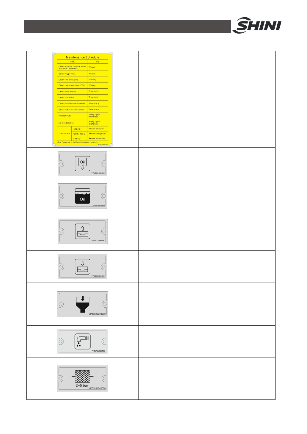
1.5.2 Signs and Labels
Please according to schedule to make regular
maintenance.
Oil outlet valve: oil discharge outlet for renewing oil.
High liquid level: the highest oil level to which machine
can reach under room temperature.
From mould: connector for circulating water/oil coming
from mould.
To mold: connector for circulating water/ oil to go to
mould.
Oil inlet: oil filler for machine.
Overflow
1. To maintain temperature consistency, cooling water
pressure must be higher than 2 bar at all time, but
should never exceed 5 bar in any case.
2. Clean Y-shape Cooling Water Strainer periodically to
ensure perfect cooling capacity.
13(42)
Page 14

Water outlet: drainage outlet.
Water inlet: inlet for cooling water.
1.5.3 Operation Regulations
1) Before operation, make sure that cooling water is clean soft water without
pollutants.
※ Low quality water brings limescales, which may cause problems.
2) If problems of drainage or bad temperature control are noted, please clean
solenoid valve and cooling water inlet and outlet.
3) Do not move the unit when it is in operation.
4) When in need of repairing, wait until oil temperature falls below 30℃.
5) Motor overload may be caused by phase shortage, pipe obstruction,
broken bearing, etc. Motor overload relay will trip off to stop the machine
when this happens. Fixing the problems, press RESET on overload relay
to clear the alarm.
6) Before turn off the pump, wait until oil temperature falls blow 50℃. Or the
life of the unit would be affected.
1.5.4 Transportation and Storage of the Machine
Transportation
1) STM series standard oil heater are packed in crates or plywood cases with
wooden pallet at the bottom, suitable for quick positioning by fork lift.
2) After unpacked, castors equipped on the machine can be used for ease of
movement.
3) Do not rotate the machine and avoid collision with other objects during
transportation to prevent improper functioning.
4) The structure of the machine is well-balanced, although it should also be
handled with care when lifting the machine for fear of falling down.
5) The machine and its attached parts can be kept at a temperature from
-25℃ to +55℃ for long distance transportation and for a short distance, it
can be transported with temperature under +70℃.
14(42)
Page 15

Storage
1) STM series standard oil heater should be stored indoors with temperature
kept from 5℃ to 40℃ and humidity below 80%.
2) Disconnect all power supply and turn off main switch and control switch.
3) Keep the whole machine, especially the electrical components away from
water to avoid potential troubles caused by the water.
4) Plastic film should be used to protect the machine from dust and rains.
Working environment
The machine should be operated:
1) Indoors in a dry environment with max. temperature +45℃ and humidity
no more than 80%.
Do not use the machine:
1) If it is with a damaged cord.
2) On a wet floor or when it is exposed to rain to avoid electrical shock.
3) If it has been dropped or damaged until it is checked or fixed by a qualified
serviceman.
4) This equipment works normally in the environment with altitude within
3000m.
5) At least a clearance of 1m surrounding the equipment is required during
operation. Keep this equipment away from flammable sources at least two
meters.
6) Avoid vibration, magnetic disturbance at the operation area.
Rejected parts disposal
When the equipment has run out its life time and can not be used any more,
unplug the power supply and dispose of it properly according to local code.
Fire Hazard
In case of fire, Co2 dry powder fire extinguisher should be applied.
Please abide by the safety guide when you operate the machine so as to
prevent damage of the machine and personal injuries.
15(42)
Page 16
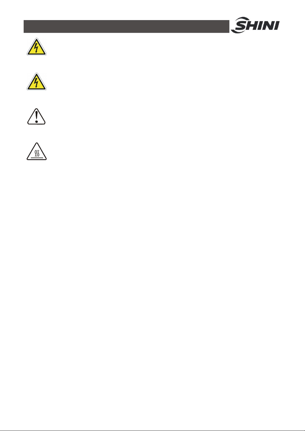
All electrical components should be installed by qualified electricians.
Turn off main switch and control switch during repair and maintenance.
Warning! High voltage!
This mark is attached on the cover of the control box.
Warning! Be careful!
Be more careful when this mark appears.
Warning!
High temperature, take care of hands! This label is attached on the surface
of heating parts.
1.6 Exemption Clause
The following statements clarify the responsibilities and regulations born by any
buyer or user who purchases products and accessories from Shini (including
employees and agents).
Shini is exempted from liability for any costs, fees, claims and losses caused by
reasons below:
1) Any careless or man-made installations, operation and maintenances
upon machines without referring to the Manual prior to machine using.
2) Any incidents beyond human reasonable controls, which include
man-made vicious or deliberate damages or abnormal power, and
machine faults caused by irresistible natural disasters including fire, flood,
storm and earthquake.
3) Any operational actions that are not authorized by Shini upon machine,
including adding or replacing accessories, dismantling, delivering or
repairing.
4) Employing consumables or oil media that are not appointed by Shini.
16(42)
Page 17
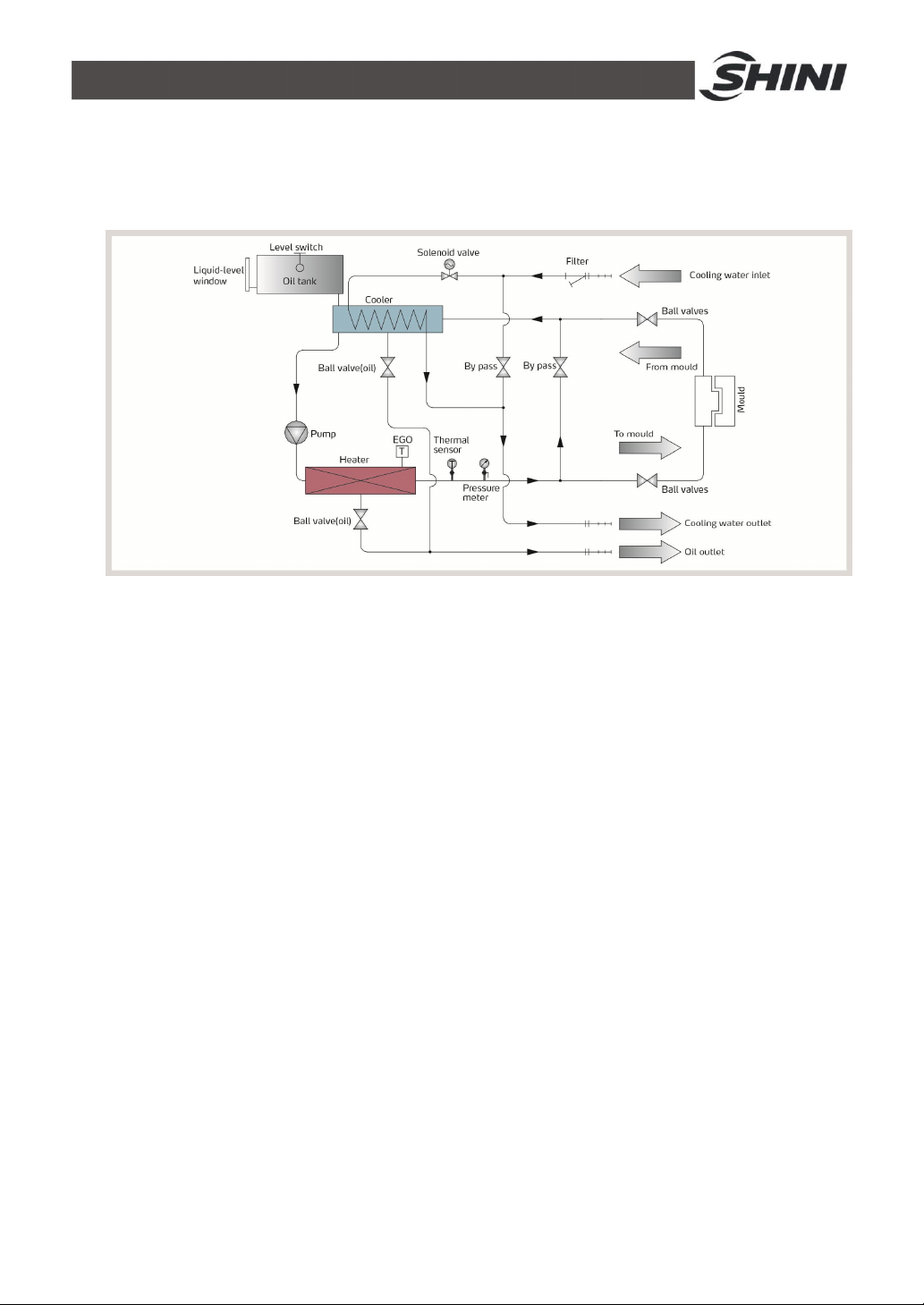
2. Structure Characteristics and Working Principle
2.1 Working Principle
Picture 2-1: Working Principle
The high temperature oil returns to the machine and then be pressured by pump
to the heater. After being heated, oil will be forced to the mould and continue the
circle. In the process, if the oil temperature is too high, system will activate the
solenoid valve to let cooling water cool down high temperature oil indirectly until
the temperature is down to the system requirement. If the temperature keeps
increasing and reaches to the set point of EGO, the system will sound alarm and
stop operation. The system will have low level alarm and stop working if oil level
falls down below the set point.
17(42)
Page 18
3. Installation and Debugging
3.1 Installation Space
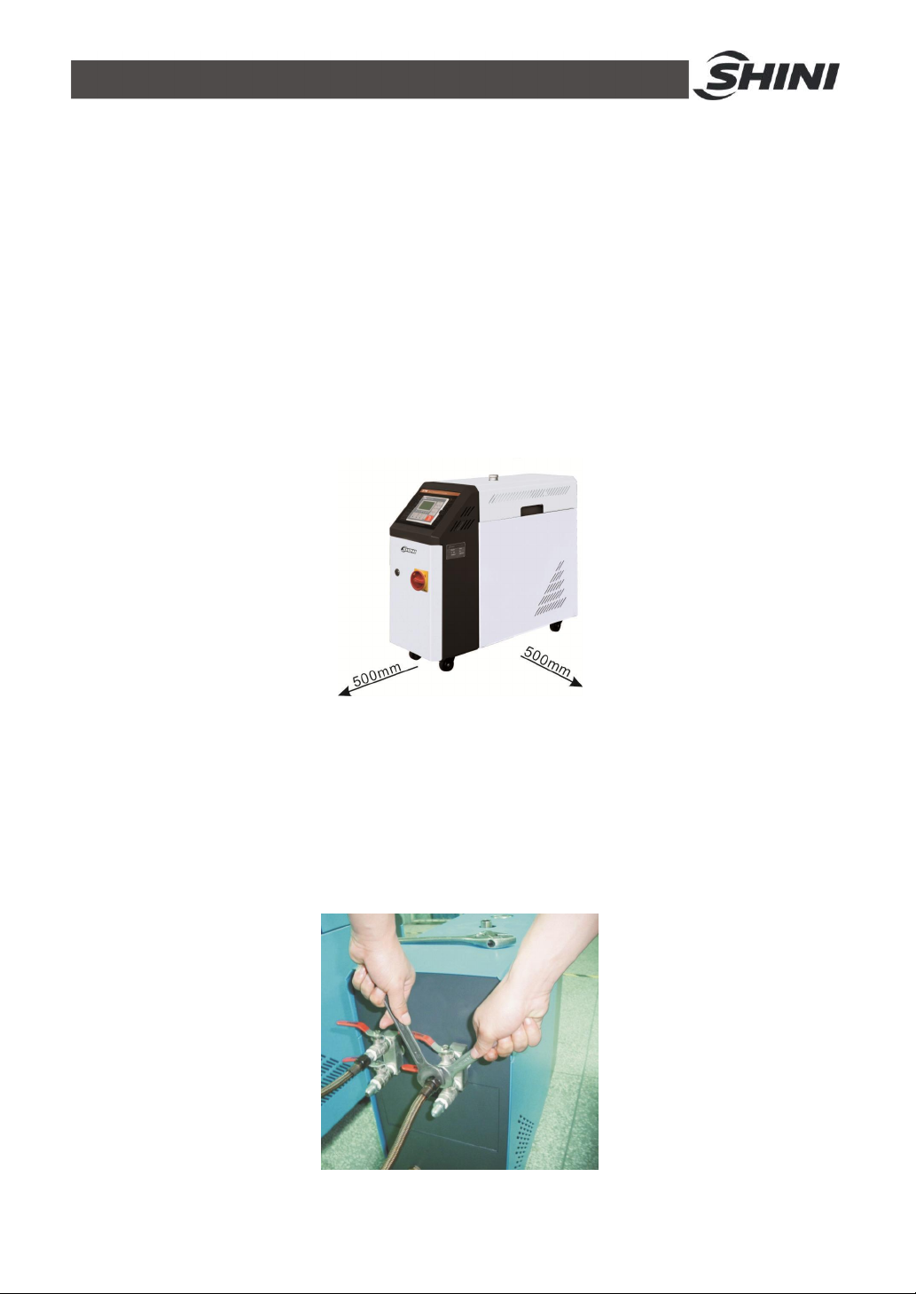
During installation of the machine, keep at least 500mm installation space around
the machine as shown by the picture. Do not install the machine in a position
crowded with other objects. This would cause inconvenience to operation,
maintenance and repair.
Do not sit on the machine.
Keep away flammable and explosive goods.
Picture 3-1: Installation Space
3.2 Mould and Water Coupling
1) When connect mould coupling with pipes from the mould. Use a spanner
to secure one end of the coupling, insert mould connecting pipe and fasten
it by another spanner.
Picture 3-2: Mould and Water Coupling 1
18(42)
Page 19
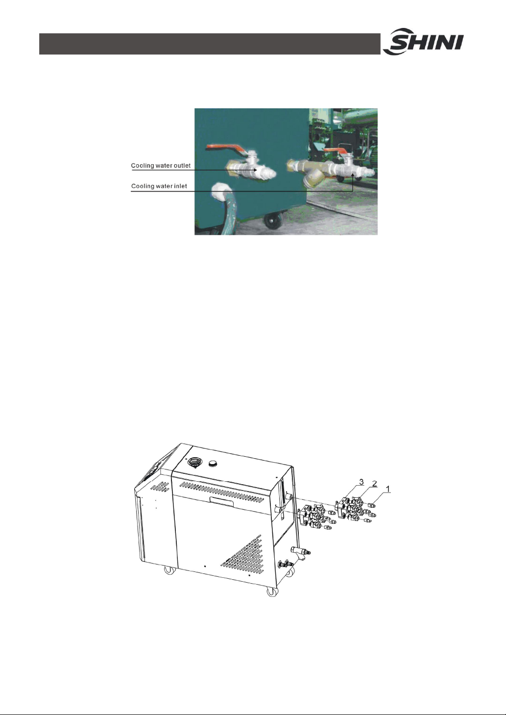
Notice: Cooling water inlet and outlet are as below, pay attention
to the direction!
Picture 3-3: Mould and Water Coupling 2
2) Connect cooling water inlet with water supply and cooling water outlet with
a drainage pipe. After that, turn on water supply.
3.3 Power Supply
Make sure that power supply is the same as required before installation.
Mould heater are generally set to be used with 3Ф 400V power supply or other
specifications according to customers' requirement.
3.4 Options Installation
3.4.1 Installation Steps for Options Water Manifold (Dewaxing)
1) Install copper joint to the level valve.
2) Install level valve with copper joint to the dewaxing water manifold.
3) Install water manifold to the machine.
19(42)
Page 20
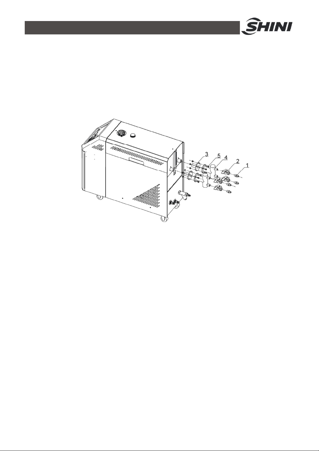
4) Install Teflon to copper joint.
Note: For the operating temperature not higher than 200℃,
Teflon with temperature resistance 200℃ is usable; for the
operating temperature from 200 to 300℃, must use Teflon with
temperature resistance 300℃.
3.4.2 Installation Steps for Options Water Manifold (Welding)
1) Install copper joint to the level valve.
2) Install level valve with copper joint to the welding water manifold.
3) Install water manifold to the machine.
4) Connect water manifold with manifold joint via screws.
5) Install Teflon to copper joint.
Note: For the operating temperature not higher than 200℃,
Teflon with temperature resistance 200℃ is usable; for the
operating temperature from 200 to 300℃, must use Teflon with
temperature resistance 300℃.
20(42)
Page 21
4. Operation Guide
4.1 Control Panel
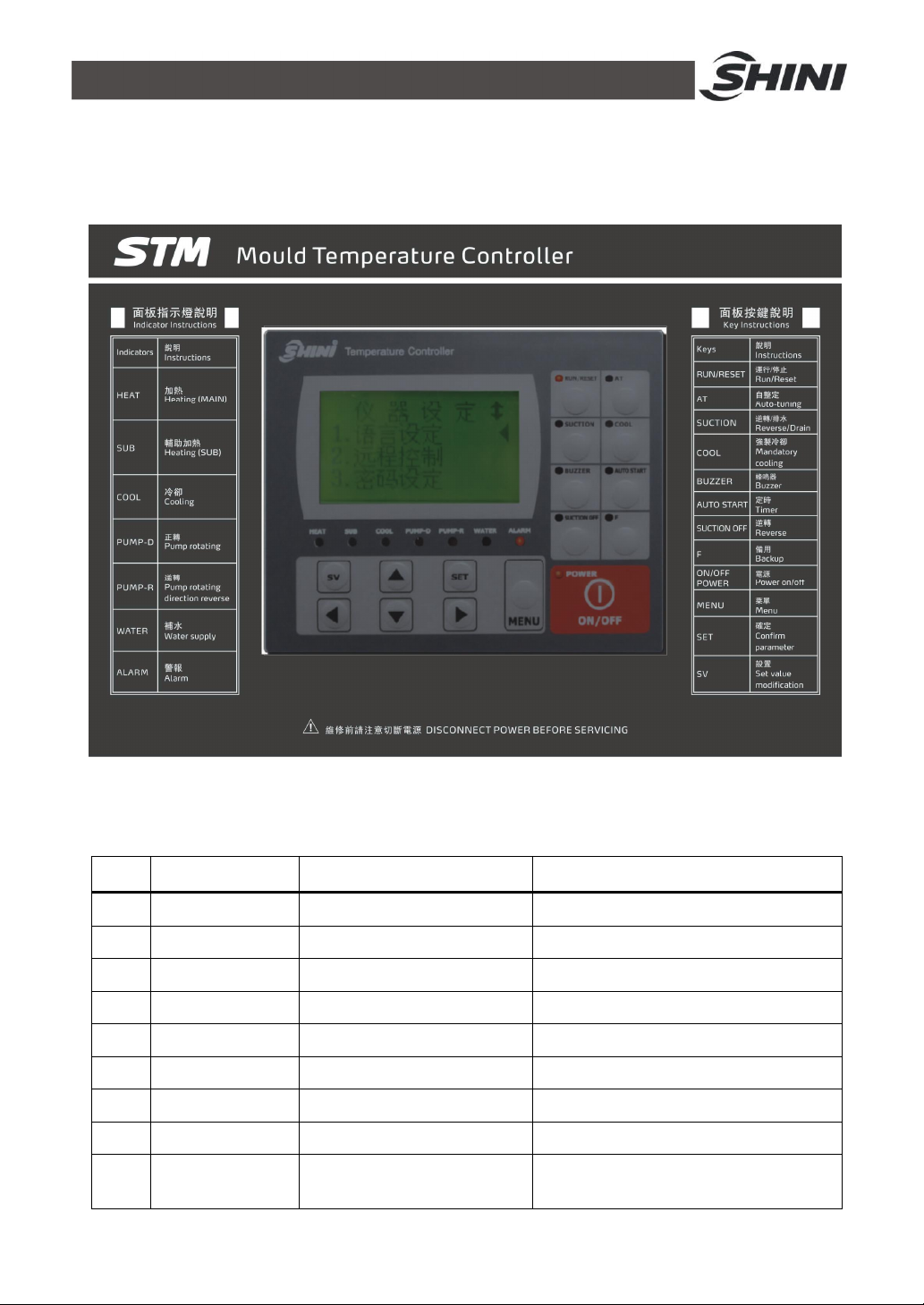
Picture 4-1: Control Panel
Table 4-1: Control Panel
No. Name Functions Remarks
1 LCD Display showing LCD
2 ON/OFF POWER Power ON, OFF shift key
3 MENU MENU setting
4 SET Parameters setting Confirm paramerters
5 SV Change set value Modify setting temp.
6 ▲/▼ Change parameters
7 ◄/► Cursor movement
8 RUN/RESET Control start and stop
9 AT
AUTO-TUNING switch start
and stop
21(42)
Initial password:0000
Auto-tuning can run during operation.
Auto-tuning cannot work under
Page 22
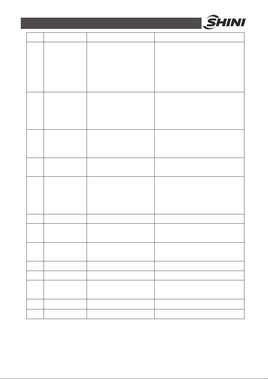
10 SUCTION
11 COOL
Control device: air-pressure
spraying function is optional
(include STM-W/O).
STM-W/O: pump reverse
drainage function
Forced cooling switch start
and stop
SUCTION and COOL
Press down the SUCTION key, the
pump runs reversely; and open the
drainage valve, the machine is in reverse
drainage mode. Note: Press the
SUCTION OFF button, the drainage
valve will close, and the machine in
reverse running (negative pressure
running mode).
Press it for 2 secs for forced cooling,
then stop heating output while output
100% cooling control. If control temp. is
below Cooling Temp, forced cooling
will be auto stopped then control turns
off.
Press “BUZZER” key and “BUZZER”
12 BUZZER Turn off buzzer
Start and stop key for
13 AUTO START
reservation
SUCTION relay switch start
14 SUCTION OFF
and stop
15 F back up Reserved key for extended function
Heating output (MAIN) display
16 HEAT
LED
Heating output (SUB) display
17 SUB
LED
18 COOL Cooling output display LED
19 PUMP_D Display pump running LED
Display pump inverse running
20 PUMP_R
LED
LED lightens; buzzer and alarm relay are
idle even error occurs.
Under SUCTION is on, this key is to turn
on or off SUCTION relay (Note: the
pump continues to run reversely).
21 WATER Display water filling LED
22 ALARM Give the alarm LED Refer to 4-4 for errors type
22(42)
Page 23
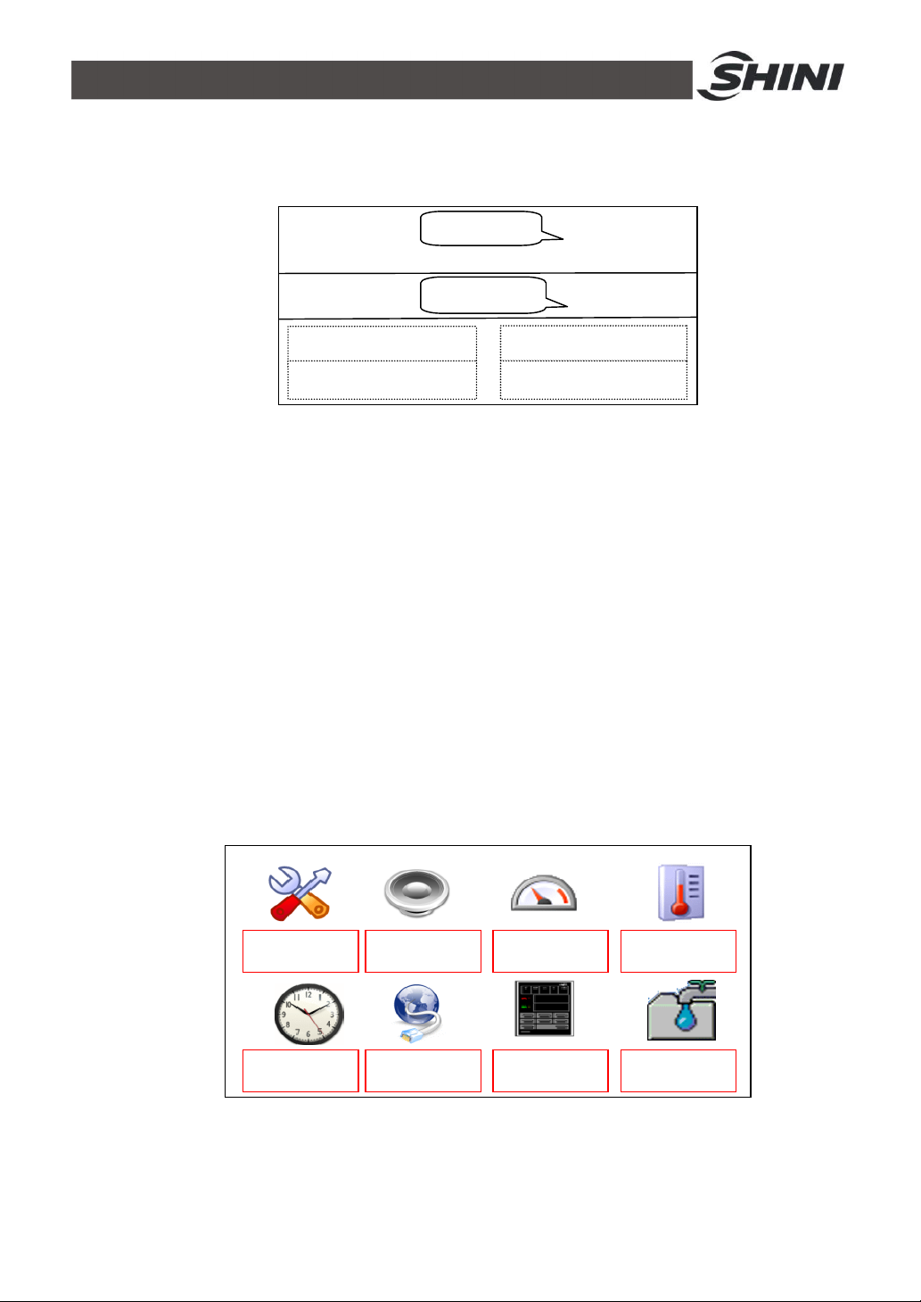
4.2 Menu Introduction
PV
SV
Current
temp.
4.2.1 Main screen
30℃
Current target
Display 1
Display 2
Display 3
Display 4
Picture 4-2: Main Menu Screen
Display 1:Display system time
Display 2:Reserved time (reserve startup) / output percentage (start temp.control)
Display 3:System state / return water temp.(Return water and mould temp.
display power consumption, and press SET key on the main screen, it displays the
temp. of return water).
Display 4:System state/mould temp. (Return water and mould temp. display
power consumption, and press SET key on the main screen, it displays mould
temp.)
Notes: The SV value range varies from different models.
4.2.2 MENU Screen
In the main screen, press the <MENU>key, it pops up the password prompt, and
input the password to enter the MENU screen, the initial password is 0000.
Con. setting Alarm setting Output setting Temp.setting
Time setting Comm. setting
Instr. setting
Refill setting
Picture 4-3: MENU Screen
23(42)
Page 24
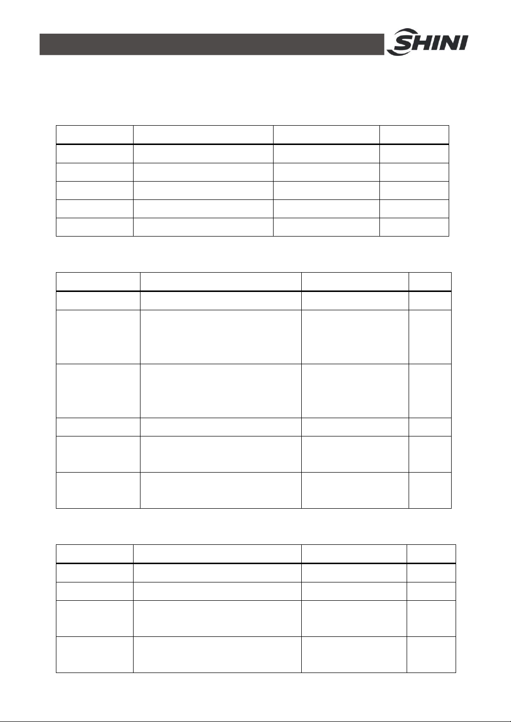
4.3 Parameter Table
in
Mould temp.
ould temp.
in normal
t reach set temp. in required
before
4.3.1 Parameter Setting Table
Table 4-2: Control Setting
Parameter Description Range Default
P proportional band 1-100℃(2 -212 ) 13℃(55 )
I heating integral time 1-999S 100S
D heating to differential time 1-999S 15S
heating cycle heating output cycle 3-60S 15S
cooling cycle cooling output cycle 1-30S 15S
Table 4-3: Alarm Setup
Parameter Description Range Default
Phase detection for three-phase detection use/not use not use
Return
water temp.
deviation
Disruption alarm Temp. sudden drop alarm 0-300℃(0= not use) 0
Heater alarm
Over temp. alarm
Control temp. and return temp.
deviation alarm (only effective
normal humidity control)
Control temp. and m
deviation alarm(only effective
humidity control)
It doesn’
time
PV>SV+overheat alarm set temp.,
it alarms and stops
0-100℃(0= not use) 0
0-100℃(0= not use) 0
0-3600S 0
0-50℃ 15℃
Table 4-4: Output Setting
Parameter Description Range Default
Auxiliary output auxiliary output OFF temp. 0-300℃(0= not use) 0
Cooling temp. forced cooling temp. 0-100℃(0= not use) 35℃
Overhaul temp.
Total running time
set machine running time
0-10000H(0= not use) 0
maintenance
total machine running time
24(42)
Page 25
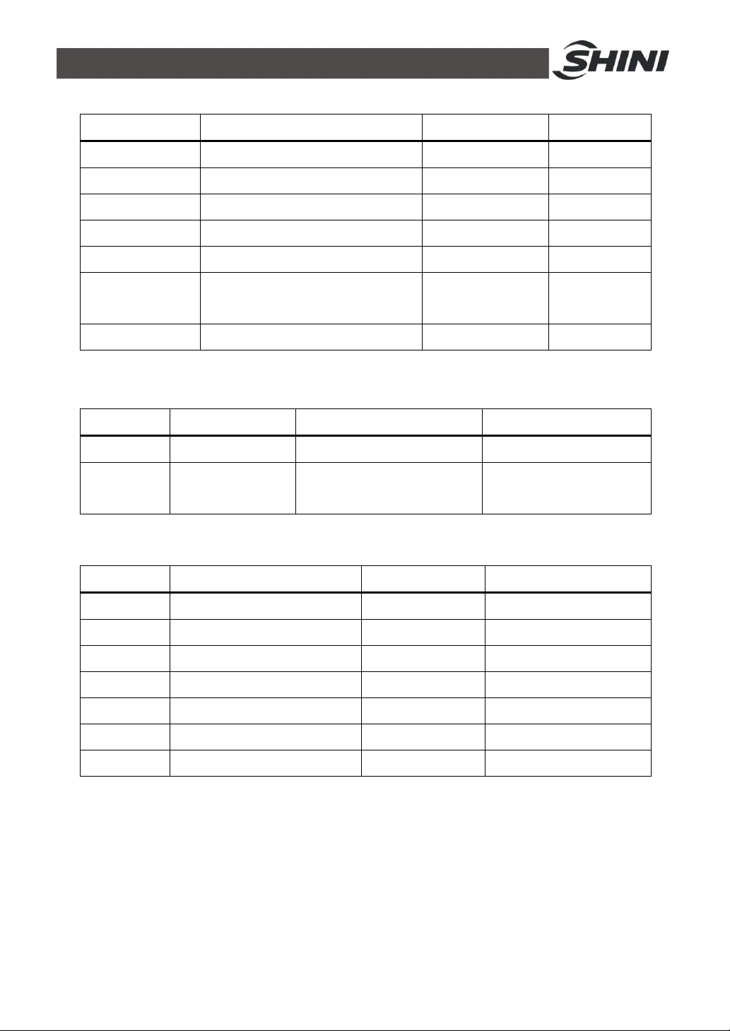
Table 4-5: Temp. Setting
Return water temp.
ower
ON/OFF time on Sun.
Parameter Description Range Default
Temp. upper limit SV upper limit temp. can be set 0-300℃ 300℃
Temp. lower limit SV upper lower temp. can be set 0-300℃ 0℃
Temp. unit ℃/℉ setting ℃、℉ ℃
Decimal point temp.value of decimal point can be set 0.1、1 1
Control temp. offset control temp. offset -100-100℃ 0℃
offset
Mould temp. offset mould temp. offset -100-100℃ 0℃
return water temp. offset -100-100℃ 0℃
Notes: The SV value range varies from different models.
Table 4-6: Time Setting
Parameter Description Range Default
Current time Current time setting hr./min./week No
Reserve
the week
Reserve p
ON/OFF OFF
ON/OFF
Table 4-7: One Week ON/OFF Setup
Parameter Description Range Default (start,stop)
Mon. Reserved ON/OFF time on Mon. hr/min.,hr/min. 01:02,08:09
Tues. Reserved ON/OFF time on Tue. hr/min.,hr/min. 02:03,09:10
Wed. Reserved ON/OFF time on Wed. hr/min.,hr/min. 03:04,10:11
Thu. Reserved ON/OFF time on Thu. hr/min.,hr/min. 04:05,11:12
Fri. Reserved ON/OFF time on Fri. hr/min.,hr/min. 05:06,12:13
Sat. Reserved ON/OFF time on Sat. hr/min.,hr/min. 06:07,13:14
Sun. Reserved
hr/min.,hr/min. 07:09,14:15
25(42)
Page 26
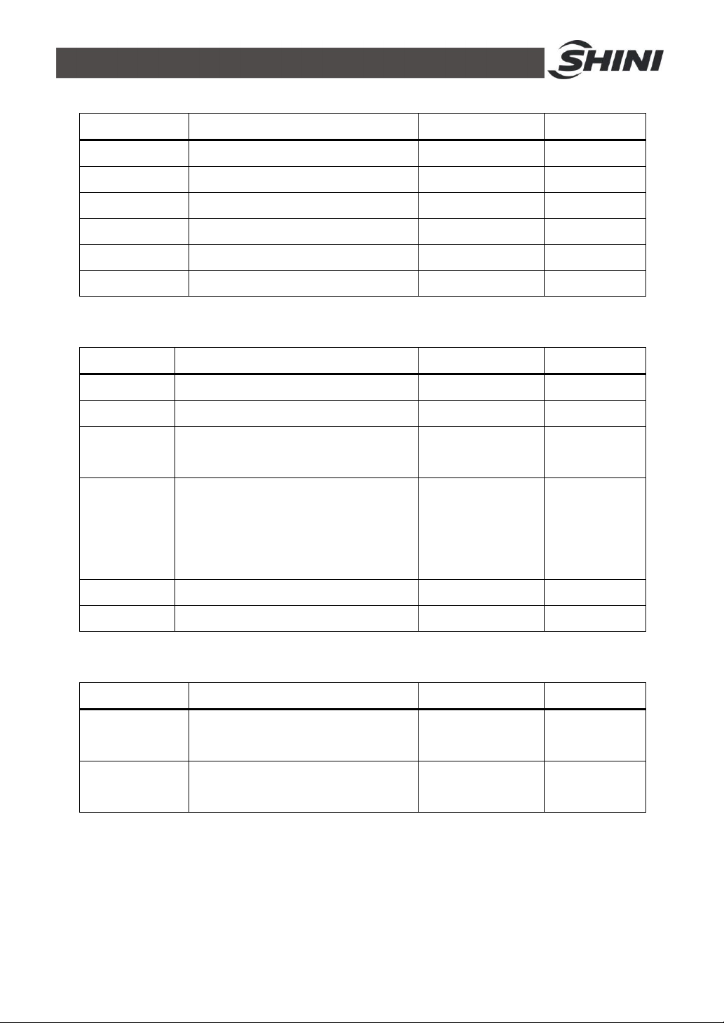
Table 4-8: Communication Setup
Parameter Description Range Default
Comm. protocol comm. protocol Modbus-RTU Modbus-RTU
Comm. unit No. comm. address 1-99 1
Comm. speed comm. speed 4800、9600、19200 9600
Comm. length data length 7,8Bit 8Bit
Stop bit stop bit 1,2Bit 1Bit
Check bit stop bit None,odd, even Even
Table 4-9: Instrument Setup
Parameter Description Range Default
Language language selection Chinese/English Chinese
Far-end setting far-end setting use/not use not use
Password
setting
Return water
and mould
temp. display
DISP TFT version
MAIN control board version
password setting 0-9999 0
Return water and mould temp. display use/not use not use
Table 4-10: Refilling Setup
Parameter Description Range Default
Startup
refill time
Intermittent
refill time
startup refill time 0-601S 0
intermittent refill time 0-600S 0
26(42)
Page 27
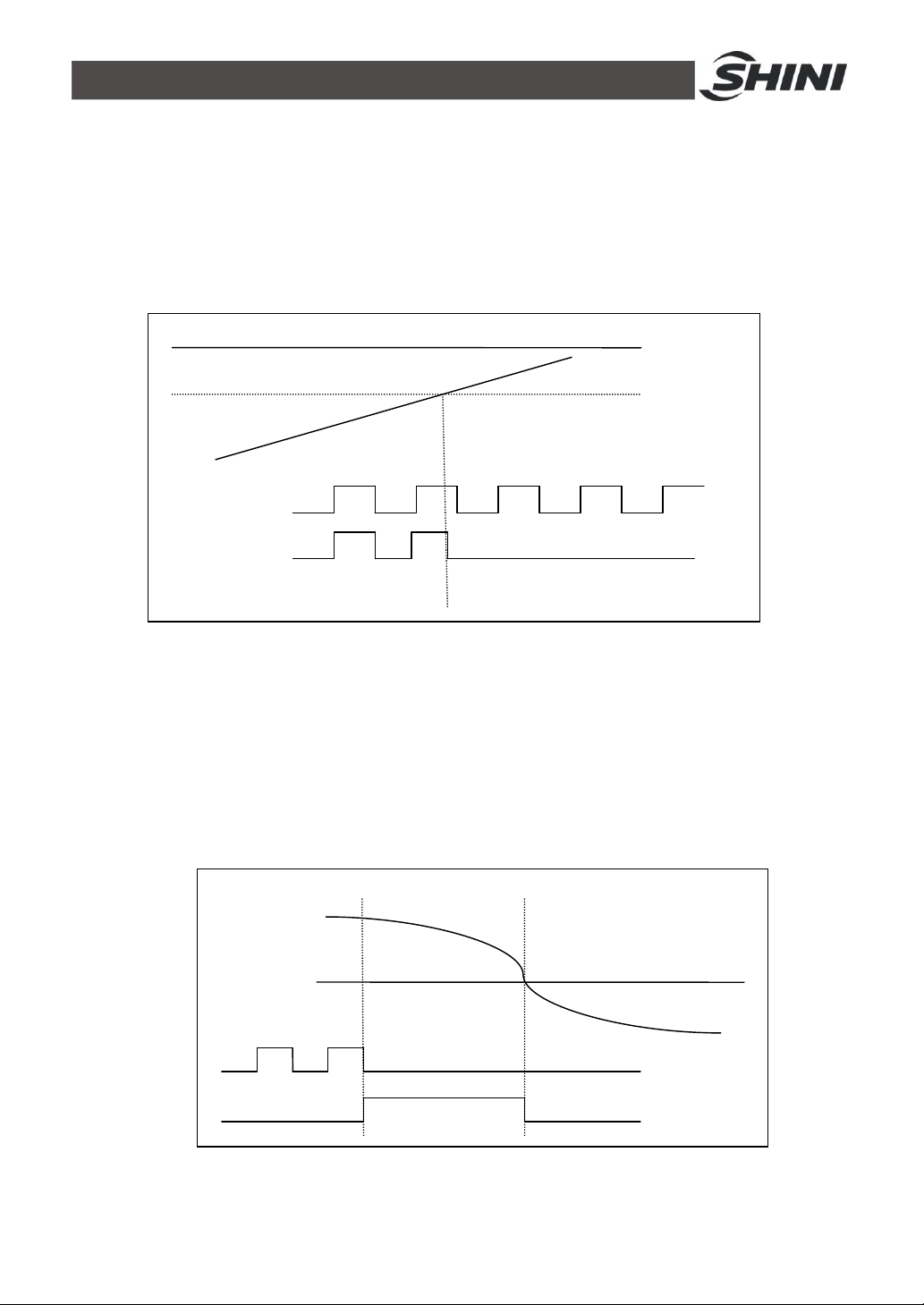
4.3.2 Output Setting
SV=100
℃
Aux. output temp.
=5℃ Control temp.
Main output
Aux. output
95℃
4.3.2.1 Main output and auxiliary output of heating control
1) When control temp. is smaller than set value, initiate main output and
auxiliary output to promptly improve the temp.
2) Alternatively select the main output and auxiliary output.
4.3.2.2 Forced cooling
1) Press the forced cooling key to stop heating and 100% output the cooling
control.
2) Control temp. is lower than the cooling temp., automatically dismiss the
forced cooling to terminate the control.
3) Forced cooling key is available to stop forced cooling for normal control.
Cooling temp.
Heating output
Cooling output
Control temp.
27(42)
Page 28
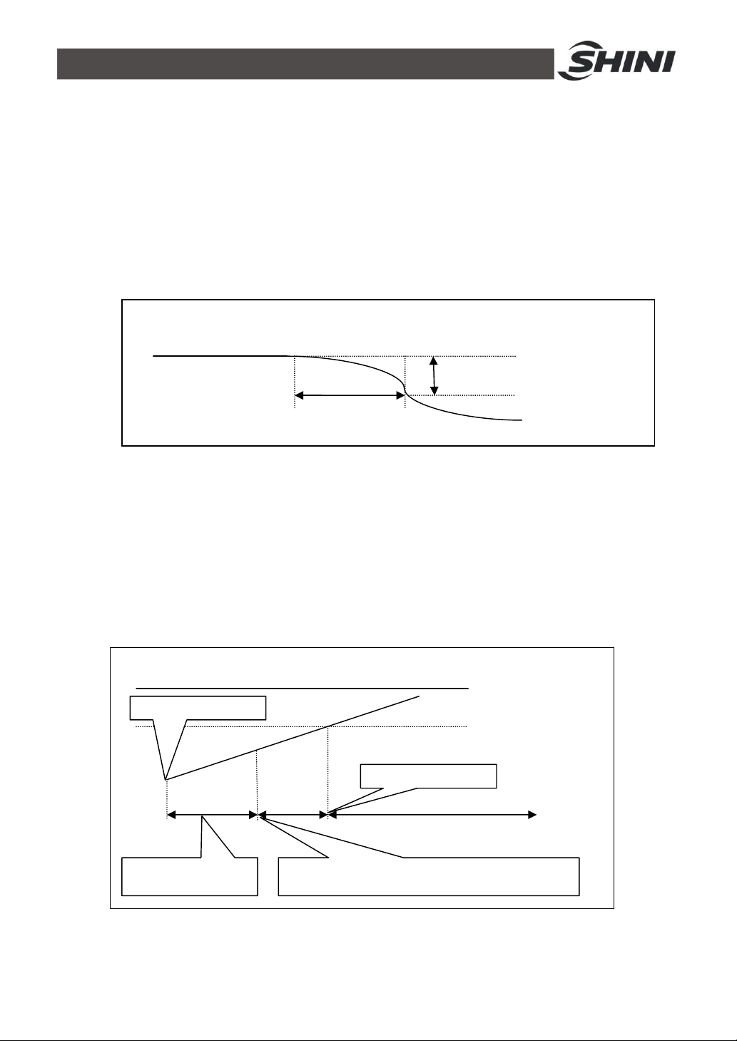
4.3.3 Alarm Settings
1S Control temp.
SV=100
℃
C
ontrol temp.
95℃(SV-5℃)
S
tart control
Heat alarm set
time
It doesn’t reach sv
-
5℃
in heating alarm set
time, the alarm will sound.
Alarm dismissed
4.3.3.1 Disruption alarms
1) If the control temp. is kept over the value of disruption alarm for 1 sec., it is
considered being interrupted, which will alarm.
2) The disruption alarm only works in controls without cooling output.
3) Once it sounds alarm, it will keep alarming till BUZZER key is pressed to
concel the alarm.
Dist. alarm sounds
4.3.3.2 Heater Alarm
1) In heater alarm setting time, it will alarm when the control temp. can’t
reach 5℃ below the set temp.
2) The heater alarm only works in controls, and once it reaches the temp.
range, the alarm will be dismissed.
3) Even it sounds the alarm, the temp. control is still effective.
28(42)
Page 29
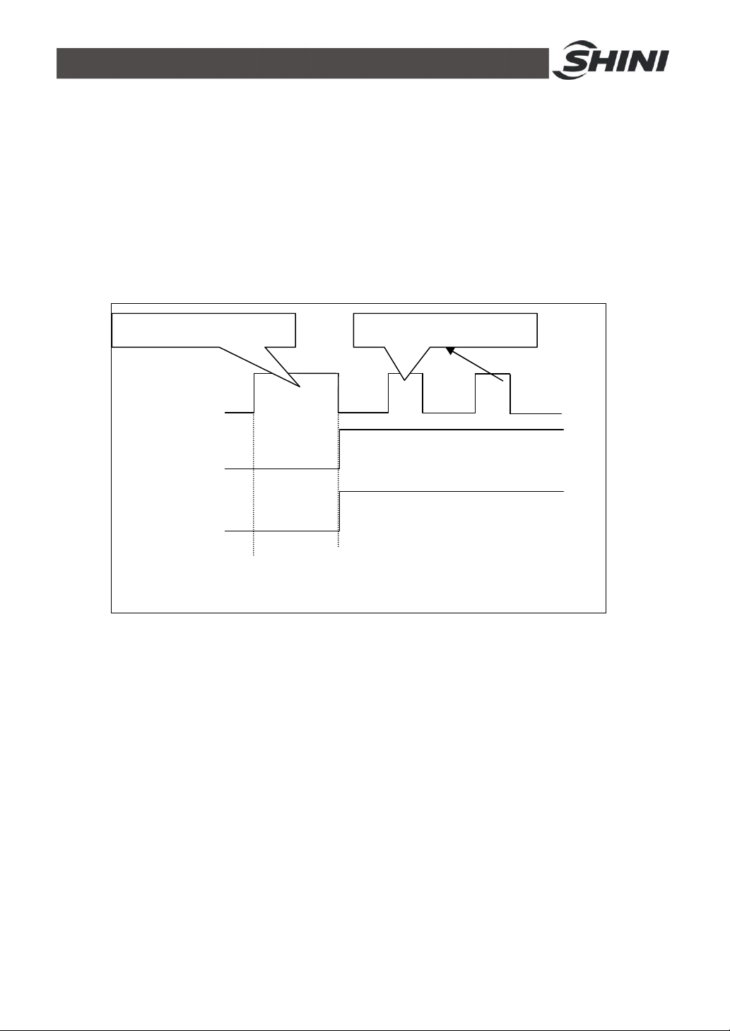
4.3.4 Startup for refilling
S
tart refill.
t
ime Refill. relay
60S 5S
P
ump
forward
running
Temp. control
▲
RUN
▲
Start temp. control
5S
1) Only after the startup time is set as 60s, and water refilling reaches the high
level that the PID starts operation.
2) When startup refilling <60S, it will refill according to set time, and the PID will
operate.
4.3.5 Auto refilling process
Presss RUN key to refill the water.
Interm. refill. time
29(42)
Page 30
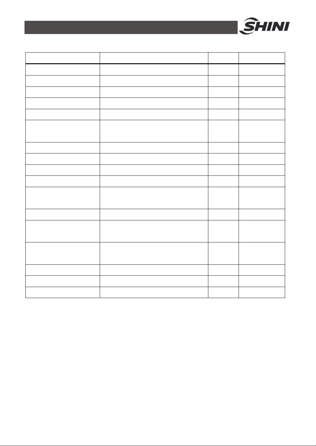
4.4 Errors and Causes
Errors Causes Alarm Temp. control
PCB erros Regulator error Occur Stop
Calibration error - Occur Stop
ADC error - Occur Stop
RJC error - Occur Stop
EEPROM error - Occur State maintain
Phase alarm
EGO over temp. EGO temp. contact input detected Occur Stop
Pump overload Pump overload contact input detected Occur Stop
Insufficient pressure Low pressure contact input detected Occur Stop
Overpressure High pressure contact input detected Occur Stop
Low water (liquid) level
Temp. window “----“display Sensor abnormal Occur Stop
Water outlet temp.
deviation
Return water temp.
deviation
Disruption alarm Control temp. sudden drop Occur state maintain
Heater alarm Control temp. doesn’t rise Occur State maintain
Over heat Overheat alarm sounds Occur Stop
Notice:
As various alarms above, the controller will activate the protective function as auto shutdown or stop running;
please re-press the “operation” to restart.
Phase shortage or
Occur
phase reverse detected
Low water (liquid) level
Occur
contact input detected
Control temp. and
Occur State maintain
water outlet temp. deviation
Control temp. and
Occur State maintain
return water temp. deviation
Stop
Stop
30(42)
Page 31
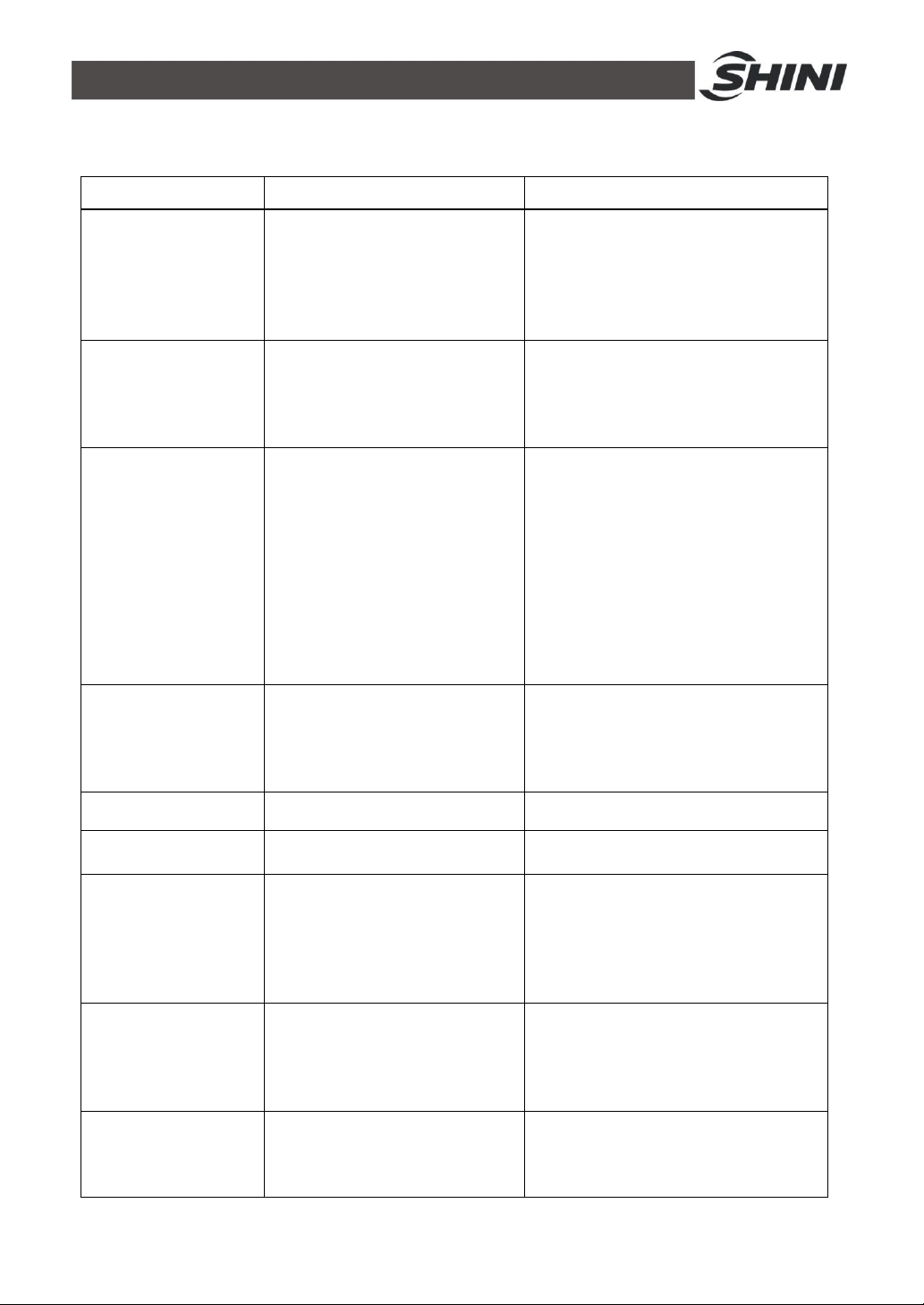
5. Trouble-shooting
Failures Possible reasons Solutions
Did not connect through power
LCD displays nothing
after switch on power
and press ON/OFF
key.
Phase alarm.
Pump overload.
EGO overheat.
Low liquid level. Oil shortage.0 Fill high temp. oil.
Temp. window
displays “----“
Once running, pump
output indicator
lightens but pump
cannot start. Afetr a
while pump still fails to
run.
Differences between
setting temperature
and actual
temperature is too big.
Temperature can't rise
up.
supply.
Main switch broken.
Power supply wires problems.
Control circuit fuse melt.
Transformer broken.
Power supply low voltage.
Phase shortage.
Phase reversal.
PCB problems.
Abnormal fluctuations of power
supply.
Pump blocked.
Pump motor problems.
Overload relay (F1) setting value
error.
EGO temperature setting
mistakes.
EGO poor temperature detecting.
Heater contactor K1 and K2
problems.
Abnormal sensor. Check and repair sensor.
PCB output relay problems.
Electrical circuit problems.
Too short time after machine
startup.
Temperature parameter setting
error.
Cooling water valve problems.
Heater contactor problems.
Heater problems.
Thermocouple problems.
PCB output point problems.
Connect through power supply.
Replace main switch.
Check electrical wires.
Fix the fuse.
Replace the transformer.
Check power supply.
Check power supply.
Exchange two of the wires of power
supply.
Replace the PCB.
Check power supply.
Check the pump.
Check pump motor.
Set the setting current of overload relay
to equal to 1.1 times of motor rated
current. Please refer to Mian
Components for detailed description of
overload relaly.
Reset overload relay:
Wait for one minute, then press the blue
button to reset.
Correctly set EGO temperature. (EGO
temperature setting value= temperature
setting value+10)℃
Replace EGO.
Replace the contactor.
Check or replace the PCB.
Check electrical circuit.
Wait for a while.
Check temperature parameters.
Please refer to the standard manual of
setting parameters.
Replace solenoid valve.
Replace the contactor.
Replace pipe heater.
Replace thermocouple.
Check and repair PCB.
31(42)
Page 32
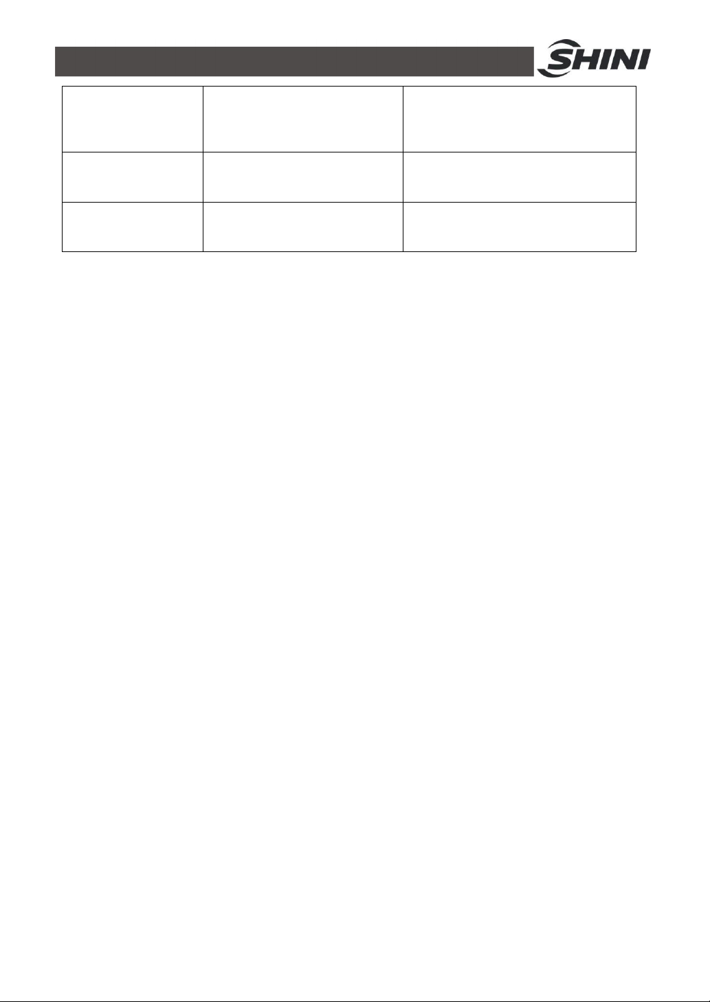
Circuit breaker tripping
off at turning on main
switch.
Circuit breaker tripping
off at turning on pump
switch.
Circuit breaker
trippingoff after short
heater output.
Short circuit of main circuit.
Transformer short circuit or
connected with earth wire.
Problems of circuit breaker.
Pump motor coil short circuit.
Problems of circuit breaker.
Heater tube short circuit or shell
contact.
Problems of circuit breaker.
Check electrical wire.
Replace circuit breaker.
Check pump motor.
Replace circuit breaker.
Replace heater tube.
Replace circuit breaker.
32(42)
Page 33
6. Maintenance and Repair
Pay attention to the following rules during maintenance:
1) Need at least two persons present when checking the machine. Let the
machine cool down, turn off power supply, drain out the oil and water.
Make sure enough place before checking and maintenance.
2) The machine works in high temperature. Stop the machine, wait it to cool
down. Put on protective gloves before servicing or maintenance.
3) In order to prolong the life of the machine and to prevent accidents, check
the machine at a fixed frequency.
4) During operation, the oil is heated up to a high temperature, wait it to fall
below 50℃ to perform repairing or maintenance.
( Please note that it is dangerous to check or tear down the
machine during operation.)
33(42)
Page 34
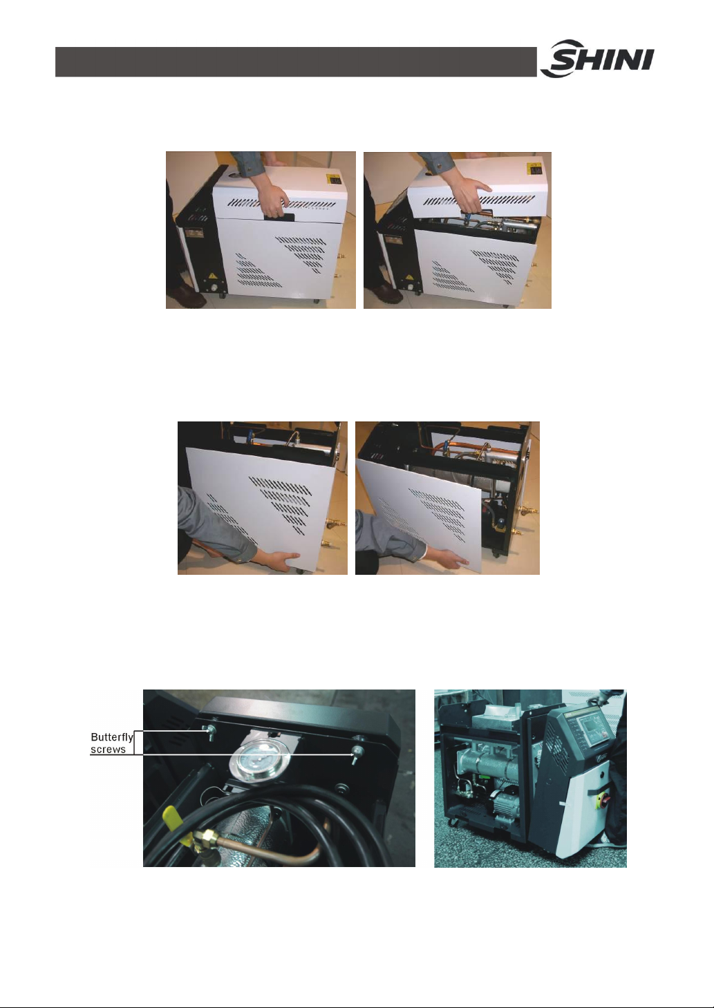
6.1 Open the Covers
1) Lift the top cover gently to open it. (Refer to the pictures below)
Picture 6-1: Open the Covers 1
2) Pull the bottom of side cover outward, and lift it to open. (Refer to the
pictures below)
Picture 6-2: Open the Covers 2
3) Open the cover of control box. Screw off two butterfly screws to unlock the
cover. (Refer to the pictures below)
Picture 6-3: Open the Covers 3
34(42)
Page 35
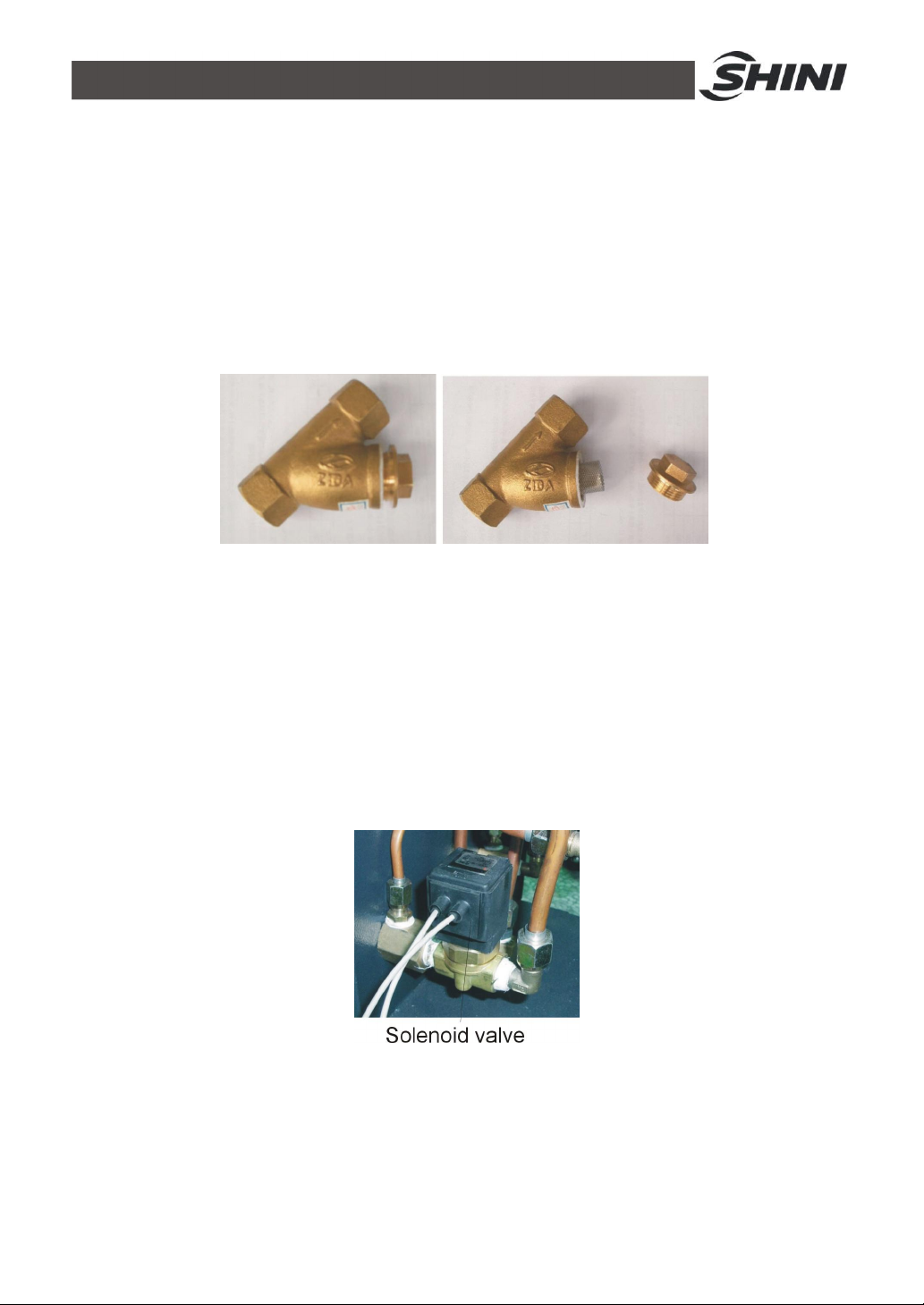
6.2 Y Type Strainer
1) Clean soft water should be used as cooling water. Y type strainer is used
in the strainer to stop impurities and pollutants entering into water pipe.
2) Impurities or pollutants may cause errors and bad temperature control.
Clean Y type strainer periodically.
3) Cleaning steps: turn off power and cooling water supply. Open the cover
of Y type strainer to clean the strainer (as below picture).
Picture 6-4: Y Type Strainer
6.3 Solenoid Valve
Replace solenoid valve:
1) Open machine top cover(refer to 6.1)
2) Take down right side cover(refer to 6.1)
3) Unfix the solenoid valve for replacement.
4) Install the covers in a reverse order.
Picture 6-5: Solenoid Valve
35(42)
Page 36
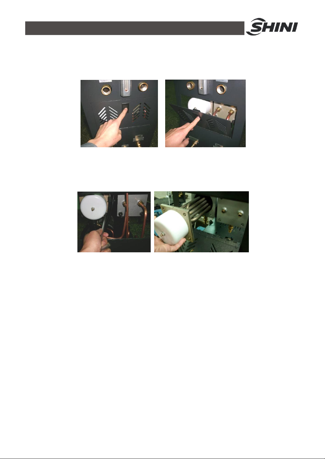
6.4 Pipe Heater
1) Pull the black door locker downward, then draw it outward to open
machine rear cover. (Refer to pictures below)
Picture 6-6: Pipe Heater 1
2) Unscrew the screws of heater cap and take it down. (Refer to pictures
below)
Picture 6-7: Pipe Heater 2
3) Use the thinner or cloth dipped with thinner to clean the pipe heater. After
the cleaning, put the pipe heater in the cool place for thinner total
volatilization.
4) Install the pipe heater to the machine according to above opposite orders.
6.5 Cooling Pipes
After long use of the machine, as it is heated by high temperature, the heat
transfer oil would carbonize and accumulate on machine pipeline. Too much of
carbonization would lower the cooling efficiency of the cooling pipe. So it is
needed to clean the carbon deposited on the cooling pipe. The cleaning steps are
as below:
1) Pull the black door locker downward, then draw it outward to open
machine rear cover. (Refer to pictures below)
36(42)
Page 37
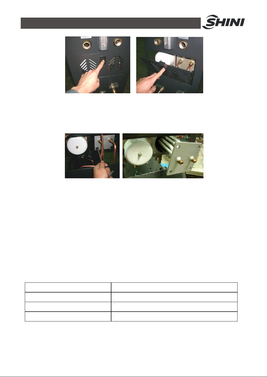
Picture 6-8: Cooling Pipes 1
2) Screw off the screws of cooling pipe to take it out. (Refer to pictures
below)
Picture 6-9: Cooling Pipes 2
3) Use the thinner or cloth dipped with thinner to clean the cooling pipe. After
the cleaning, put the cooling pipe in the cool place for thinner total
volatilization.
4) Install the cooling pipe to the machine according to above opposite orders.
Note: Because the heat transfer oil may become carbonized
agglutination after a long time heating, which will shorten the
lifespan of the pump, so it is suggested to replace every three
monthes.
Designated oil medium “shell Heat Transfer Oil S2”.
Flash point 210℃
Fire point 255℃
Initial boiling point 355℃
Signition point 360℃
Note: For failures caused by heat transfer oil of other brands,
our after-sale service is not available.
37(42)
Page 38

6.6 Printed Circuit Board
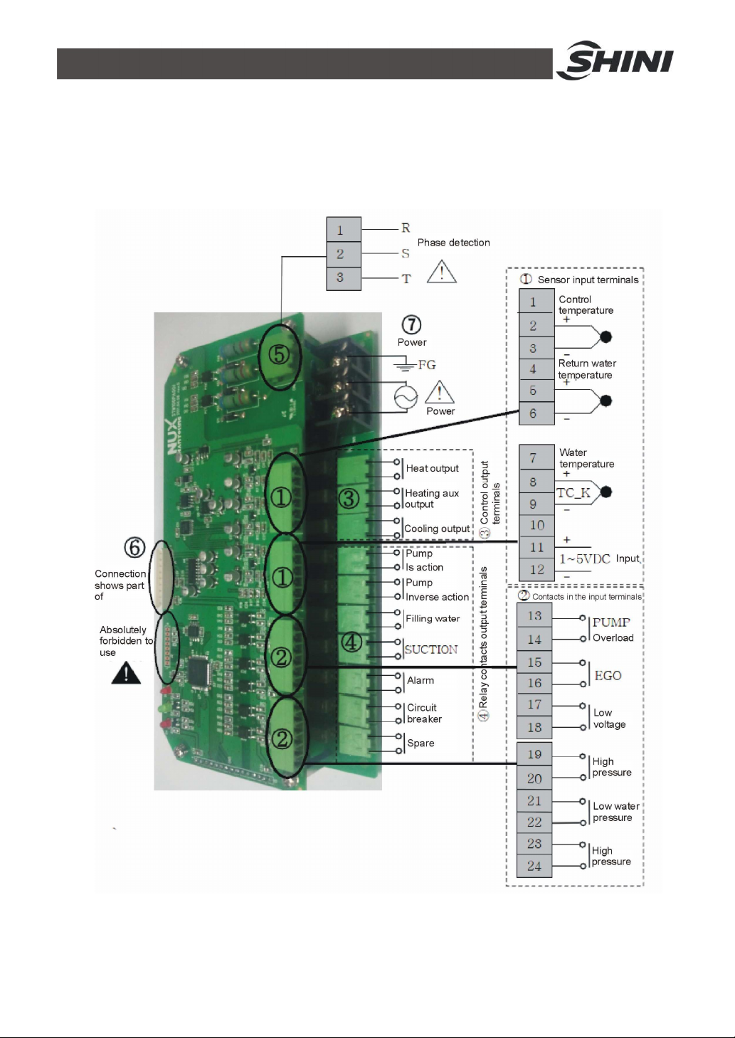
MAIN terminal board drawing (refer to next page for terminal position and
number).
① SENSOR TERMINAL1 (sensor terminal)
2, 3 : control temp. sensor termnal
5, 6 : retuen water temp. sensor terminal
8, 9 : water out temp. sensor terminal
11, 12 : 1~5V input terminal
② DI TERMINAL (contactor input terminal)
13, 14 : pump overload contactor input terminal
15, 16 : EGO overheat contactor input terminal
17, 18 : underpressure contactor input terminal
19, 20 : overpressure contactor input terminal
21, 22 : lower water limit contactor input terminal
23, 24 : upper water limit contactor input terminal
③ OUTPUT TERMINAL (output terminal for controlling)
1, 2 : heating control output MAIN (RELAY output)
3, 4 : heating control output SUB (RELAY output)
5, 6 : coling control output (RELAY output)
④ DO TERMINAL (relay contactor output terminal)
1, 2 : pump running contactor output terminal
3, 4 : pump inverse running contactor output terminal
5, 6 : backup water contactor output terminal
7, 8 : SUCTION contactor output terminal
9, 10 : alarm contactor output terminal
11, 12 : relay contactor output terminal
13, 14 : reserve
⑤ PHASE CHECK TERMINAL (phase detect terminal)
1 : R phase connect terminal
2 : S phase connect terminal
3 : T phase connect terminal
⑥ DISPLAY CN (connect terminal for dispaly)
38(42)
Page 39
Connect stub cable with STM100.
⑦ POWER TERMINAL (power supply terminal)
1 : FG terminal
2, 3 : power supply terminal (100~240VAC)
39(42)
Page 40
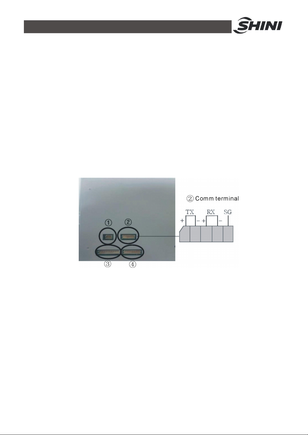
6.7 Displayer Terminal Connecting Diagram
① DI TERMINAL
1, 2: Run/stop di terminal
② COMM TERMINAL
1, 2, 3, 4: rs485 Comm terminal
5:Earth terminal
③ MAIN CN
Connet to the electric cables which also connected with stm100
④ TEST PIN
Test pin No connection
40(42)
Page 41
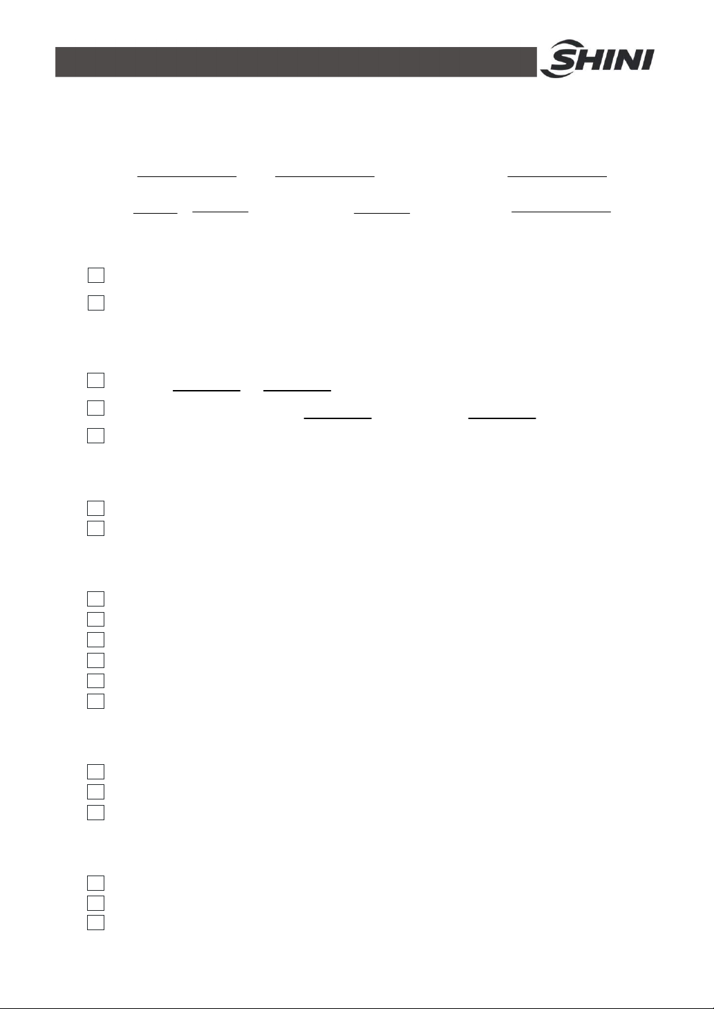
6.8 Maintenance Schedule
6.8.1 About the Machine
Model SN Manufacture date
Voltage Ф V Frequency Hz Power kW
6.8.2 Installation & Inspection
Check the installation space is enough as required.
Check the pipes are correctly connected.
Electrical installation
Voltage: V Hz
Fuse melting current: 1 Phase A 3 Phase A
Check phase sequence of power supply.
6.8.3 Daily Checking
Check machine startup function.
Check all the electrical wires.
6.8.4 Weekly Checking
Check loose eletrical connections.
Check and clean Y type filter 1.
Check solenoid valve.
Check motor overload and phase reversal alarm function.
Check whether pipeline joints are under looseness.
Check the sensitivity of EGO.
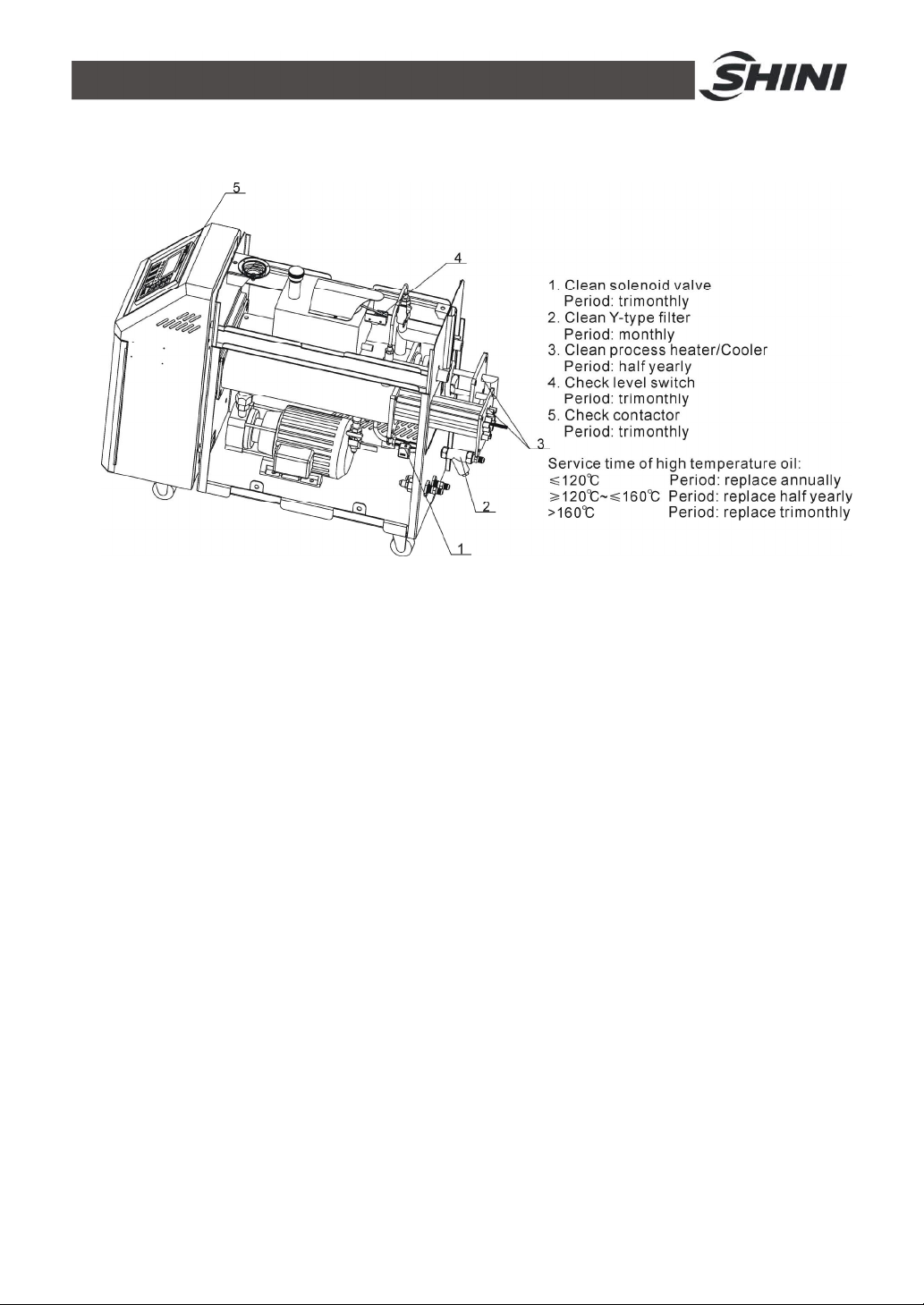
6.8.5 Trimonthly Checking
Check level switch.
Check the contactor 2.
Replace the hot kerosene with a using temperature above 160 degree 3.
6.8.6 Half-yearly Checking
Check damaged pipes.
Clean process heater/cooler.
Check indicator and buzzer.
41(42)
Page 42
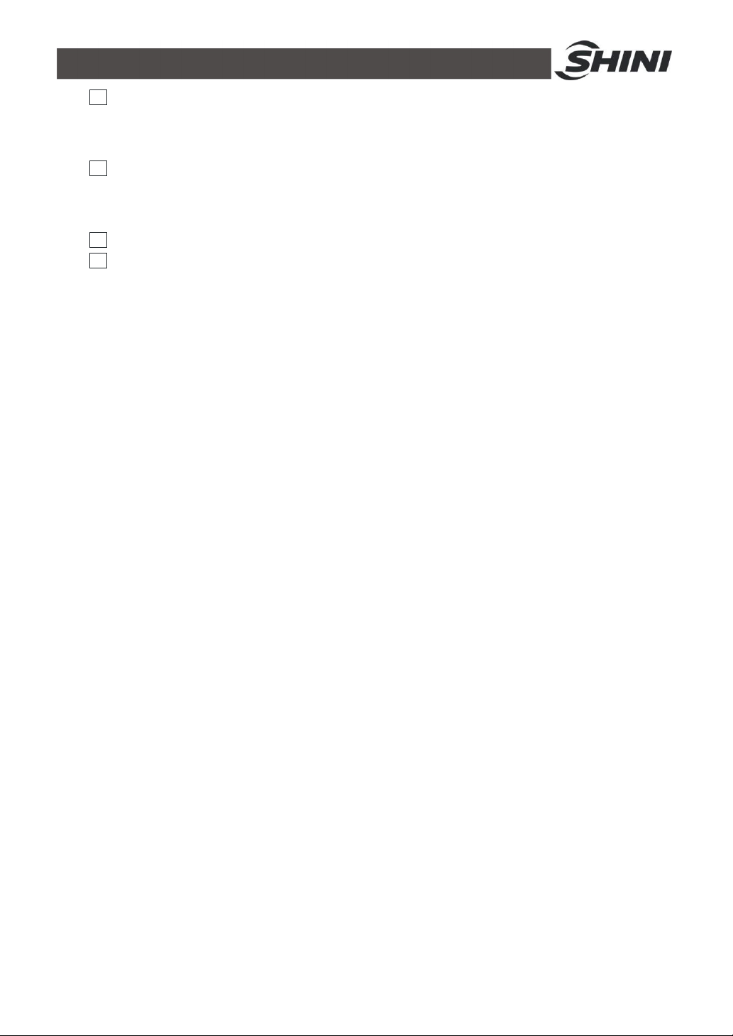
Replace the hot kerosene with a using temperature above 120~160 degree 4.
6.8.7 Yearly Checking
Replace the hot kerosene with a using temperature above 120 degree 5.
6.8.8 3 year Checking
PC board renewal.
No fuse breaker renewal.
Note: 1. Y-type filter has the function of filling water cooling protection effect, be sure the
waterway are clear to avoid cooling failure.
2. Manufacturer laboratory data for AC contactor is two million times in life. we suggest
service life for one million four hundred thousand times, if work eight hours per day,
recommended replacing frequency is 1.5 years, if work day and night, replacement is
suggested to be done every six months.
3. Hot kerosene coke will influence the detection accuracy of internal temperature probe
and the efficiency of heat elements, three months replacing frequency is suggested.
4. Hot kerosene coke will influence the detection accuracy of internal temperature probe
and the efficiency of heat elements, six months replacing frequency is suggested.
5. Hot kerosene coke will influence the detection accuracy of internal temperature probe
and the efficiency of heat elements, suggested replacing frequency is one year.
42(42)
 Loading...