


SICC-A Series
Air-cooled Central Water Chiller
Date: Apr, 2013
Version: Ver.B (English)


Contents
1. General Description..................................................................................9
1.1 Coding Principle.................................................................................10
1.2 Feature...............................................................................................10
1.3 Technical Specifications.....................................................................12
1.3.1 SICC-A Series Outline Dimensions.........................................12
1.3.2 The Illustrative Drawing of SICC-A Modules Grouping............15
1.3.3 Specification............................................................................19
1.4 Safety Regulations.............................................................................20
1.4.1 Notice Items for Safe Operation..............................................20
1.4.2 Safety Signs and Labels..........................................................21
1.4.3 Signs and Labels.....................................................................21
1.5 Exemption Clause..............................................................................22
2. Structure Characteristics and Working Principle.................................23
2.1.1 Working Principle.....................................................................23
2.1.2 Working Flow Instruction.........................................................23
2.2 Electrical Diagram..............................................................................24
2.2.1 Main Circuit (SICC-60A)..........................................................24
2.2.2 Control Circuit (SICC-60A)......................................................25
2.2.3 Electrical Components Layout (SICC-60A)..............................26
2.2.4 Electrical Components List (SICC-60A)...................................27
2.2.5 Main Circuit (SICC-90A)..........................................................28
2.2.6 Control Circuit (SICC-90A)......................................................29
2.2.7 Electrical Components Layout (SICC-90A)..............................30
2.2.8 Electrical Components List (SICC-90A)...................................31
2.2.9 Main Circuit (SICC-120A)........................................................32
2.2.10 Control Circuit (SICC-120A)....................................................34
2.2.11 Electrical Components Layout (SICC-120A)............................35
2.2.12 Electrical Components List (SICC-120A).................................36
3. Installation and Debugging.....................................................................37
3.1 Installation Notice Items.....................................................................37
3.2 Select Installation Site........................................................................38
3(61)

3.3 Bearing Platform................................................................................39
3.4 Hanging and Transporting of the Unit................................................40
3.5 Water System Tubing.........................................................................41
3.6 Combined Installation of Modules......................................................43
3.7 Essentials for Electric Wiring..............................................................43
3.8 Power Connection..............................................................................44
4. Operation Guide......................................................................................45
4.1 Control Panel.....................................................................................45
4.2 The Make Up and Layers of the Display Interface.............................45
4.2.1 The Make up of the Display Interface......................................45
4.2.2 Interfaces Show.......................................................................45
4.3 Main Working Interface......................................................................46
4.3.1 Interface Demonstration..........................................................46
4.4 Selecting Interface of System Function..............................................46
4.4.1 Interface Demonstration..........................................................47
4.4.2 Interface Operation..................................................................47
4.5 System Parameter Setup Interface....................................................47
4.5.1 Interface Demonstration..........................................................47
4.5.2 Interface Operation..................................................................47
4.6 Inquiry Parameters of the Module......................................................47
4.6.1 Interface Demonstration..........................................................47
4.6.2 Interface Operation..................................................................48
4.7 System Time Setup............................................................................48
4.7.1 Interface Demonstration..........................................................48
4.7.2 Interface Operation..................................................................48
4.8 System Configuration.........................................................................48
4.8.1 Interface Demonstration..........................................................48
4.8.2 Interface Instruction.................................................................48
4.8.3 Interface Operation..................................................................49
4.9 Unit Running Settings........................................................................50
4.9.1 Interface Demonstration..........................................................50
4.9.2 Interface Operation..................................................................50
4.10 Parameter Setting..............................................................................50
4.10.1 Interface Demonstration..........................................................50
4(61)

4.10.2 Interface Operation..................................................................50
4.11 Unit Running Setup............................................................................51
4.11.1 Interface Demonstration 1.......................................................51
4.11.2 Interface Demonstration 2.......................................................51
4.11.3 Interface Instruction.................................................................51
4.11.4 Interface Operation..................................................................51
4.12 Inquiry Module Temperature..............................................................52
4.12.1 Interface Demonstration..........................................................52
4.12.2 Interface Instruction.................................................................52
4.12.3 Interface Operation..................................................................52
4.13 Inquiry Faults......................................................................................52
4.13.1 Interface Demonstration..........................................................52
4.13.2 Interface Instruction.................................................................53
4.14 The Configuration of Module Unit.......................................................53
5. Trouble-shooting.....................................................................................57
6. Maintenance and Repair.........................................................................58
6.1 Daily Repair and Check Items............................................................59
6.2 Monthly Periodical Checking Items....................................................59
6.3 Monthly Periodical Checking..............................................................59
6.4 Maintenance Schedule.......................................................................60
6.4.1 About the Machine...................................................................60
6.4.2 Installation & Inspection...........................................................60
6.4.3 Daily Checking.........................................................................60
6.4.4 Weekly Check..........................................................................60
6.4.5 Monthly Check.........................................................................60
6.4.6 Trimonthly Checking................................................................60
6.4.7 Check Half-yearly....................................................................61
6.4.8 Yearly Checking.......................................................................61
6.4.9 3 year Checking.......................................................................61
Table Index
Table 1-1:Specification...................................................................................19
Table 2-1:Electrical Components List (SICC-60A).........................................27
5(61)

Table 2-2:Electrical Components List (SICC-90A).........................................31
Table 2-3:Electrical Components List (SICC-120A).......................................36
Picture Index
Picture 1-1:Series Outline Dimensions (SICC-60A).......................................12
Picture 1-2:Series Outline Dimensions (SICC-90A).......................................13
Picture 1-3:Series Outline Dimensions (SICC-120A).....................................14
Picture 1-4:The Illustrative Drawing of SICC-A Modules Grouping................15
Picture 1-5:SICC-60A Refrigerating Performance Curves.............................16
Picture 1-6:SICC-90A Refrigerating Performance Curves.............................17
Picture 1-7:SICC-120A Refrigerating Performance Curves...........................18
Picture 2-1:Working Principle.........................................................................23
Picture 2-2:Main Circuit (SICC-60A)..............................................................24
Picture 2-3:Control Circuit (SICC-60A)...........................................................25
Picture 2-4:Electrical Components Layout (SICC-60A)..................................26
Picture 2-5:Main Circuit (SICC-90A)..............................................................28
Picture 2-6:Control Circuit (SICC-90A)...........................................................29
Picture 2-7:Electrical Components Layout (SICC-90A)..................................30
Picture 2-8:Main Circuit 1 (SICC-120A).........................................................32
Picture 2-9:Main Circuit 2 (SICC-120A).........................................................33
Picture 2-10:Control Circuit (SICC-120A).......................................................34
Picture 2-11:Electrical Components Layout (SICC-120A)..............................35
Picture 3-1:Installation Space........................................................................38
Picture 3-2:Platform Installation.....................................................................39
Picture 3-3:Hanging and Transporting of the Unit..........................................40
Picture 3-4:Same Direction Way 1.................................................................42
Picture 3-5:Same Direction Way 2.................................................................42
Picture 3-6:Combined Installation of Modules................................................43
Picture 3-7:Essentials for Electric Wiring.......................................................44
Picture 4-1:Control Panel...............................................................................45
Picture 4-2:Interfaces Show...........................................................................46
Picture 4-3:Main Working Interface................................................................46
Picture 4-4:Selecting Interface of System Function........................................47
6(61)

Picture 4-5:System Parameter Setup Interface..............................................47
Picture 4-6:Interface Demonstration...............................................................47
Picture 4-7:Interface Demonstration...............................................................48
Picture 4-8:System Configuration...................................................................48
Picture 4-9:Unit Running Settings..................................................................50
Picture 4-10:Parameter Setting......................................................................50
Picture 4-11:Unit Running Setup 1.................................................................51
Picture 4-12:Unit Running Setup 2.................................................................51
Picture 4-13:Inquiry Module Temperature......................................................52
Picture 4-14:Sub-interface 1..........................................................................52
Picture 4-15:Sub-interface 2..........................................................................53
Picture 4-16:Sub-interface 3..........................................................................53
7(61)

8(61)

1. General Description
Read this manual carefully before operation to prevent damage of the
machine or personal injuries.
SICC-A series are applicable for cooling moulds to reduce products molding cycle,
also they are available in the cooling of equipments in order to maintain a normal
temperature. Besides, they are suitable for other industries with the need of
cooling.
Model: SICC-90A
9(61)
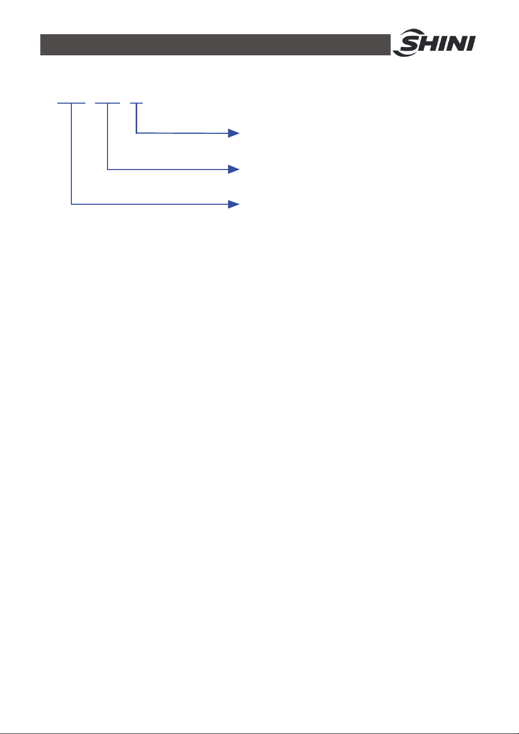
1.1 Coding Principle
SICC-xxxA
-
xx
First Three Codes: Refrigerating Capacity (kW)
Note:
Refrigerant:
No code=R22 R1=R407C R2=R410A
A=Air Cooled
Shini Central Water Chillers
CE=CE Conformity
1.2 Feature
1) Standard configuration
● Modularized design makes it easier to combine module units 1 to 15.
Cooling capacity can be enlarged by increasing the number of modules or
choose appropriate modules to connect to existing system.
● The water route of the modules can be linked via linking one module to the
inlet/outlet water tube. No need to install the inlet/outlet water tube for each
module alone. The soft rubber tube is used to connect the modules, thus it is
very convenient to construct.
● Adopts imported components like scroll compressor, expansion valve which
ensure stable performance. The whole unit will not stop due to one module
failure.
● When the whole unit is running, the microcomputer will auto adjust the
performance of each module or open / shut respective module unit
according to system load. The module unit adopts double compressors and
its power adjustable range is enlarged after combination to save up power
whenever possible.
● Wired control system enables the main unit and its controller to be separated
from each other.
2) Accessory option
● Optional RS485 communication realizes the remote monitoring and network
function.
10(61)

All service work should be carried out by a person with technical training or
corresponding professional experience. The manual contains instructions for both
handling and servicing. Chapter 6, which contains service instructions intended for
service engineers. Other chapters contain instructions for the daily operator.
Any modifications of the machine must be approved by SHINI in order to avoid
personal injury and damage to machine. We shall not be liable for any damage
caused by unauthorized change of the machine.
Our company provides excellent after-sales service. Should you have any problem
during using the machine, please contact the company or the local vendor.
Headquarter and Taipei factory:
Tel: (886) 2 2680 9119
Shini Plastics Technologies (Dongguan), Inc:
Tel: (86) 769 8111 6600
Shini Plastics Technologies India Pvt.Ltd.:
Tel: (91) 250 3021 166
11(61)
1.3 Technical Specifications
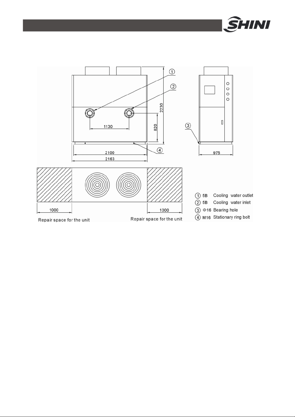
1.3.1 SICC-A Series Outline Dimensions
Picture 1-1:Series Outline Dimensions (SICC-60A)
12(61)

Picture 1-2:Series Outline Dimensions (SICC-90A)
13(61)

Picture 1-3:Series Outline Dimensions (SICC-120A)
14(61)
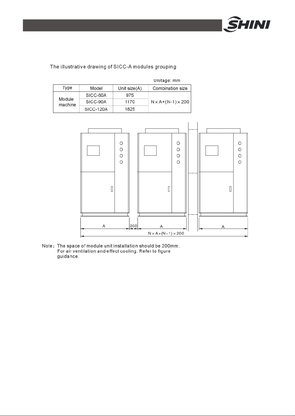
1.3.2 The Illustrative Drawing of SICC-A Modules Grouping
Picture 1-4:The Illustrative Drawing of SICC-A Modules Grouping
15(61)

Picture 1-5:SICC-60A Refrigerating Performance Curves
16(61)

Picture 1-6:SICC-90A Refrigerating Performance Curves
17(61)

Picture 1-7:SICC-120A Refrigerating Performance Curves
18(61)
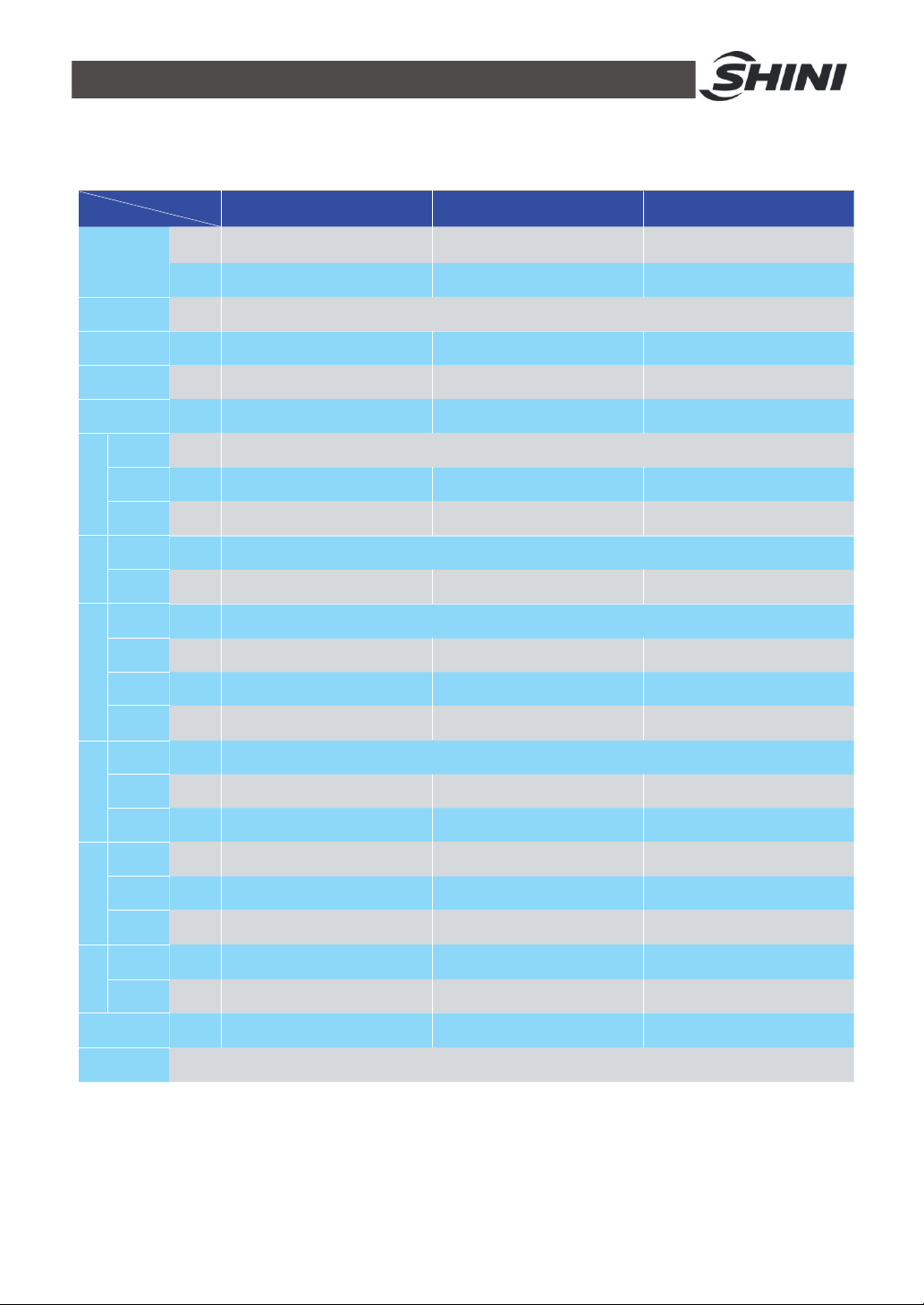
1.3.3 Specification
Table 1-1:Specification
Items
Refrigeration
Capacity
Power
Total Power
Running
Current
Startup Current
Type
Power
Crank Case
CompressorRefrigerantEvaporatorCondenser
Heater
Type
Filling
Quantity
Type
Cooling
Flow
Pressure
Loss
Water
Coupler
Type
Blower
Power
Air
Quantity
Width (W)
Model
kW
kcal/hr
---
kW
A
A
---
kW
kW
---
kg
---
m3/hr
kPa
inch
---
kW
m3/hr
mm
SICC-60A
60
51,600
19
33
140
8.5 × 2
0.07 × 2
15
10.3
27
5
1.68
26,000
2163
SICC-90A
90
77,400
3Φ, 400 / 460VAC, 50 / 60Hz
28
48
175
Hermetic Scroll
13.6 × 2
0.07 × 2
R22 ( R407C Optionaly Available )
18
Closed Shell and Tube Evaporator
15.5
39.2
5
Tube-fin Air-cooled Condenser
1.68
39,000
2163
SICC-120A
120
103,200
37
61
230
18.8 × 2
0.09 × 2
36
20.6
49
5
3.72
52,000
2163
Depth (D)
Machine
Dimensions
Height (H)
Before
Packing
After
Weight
Packed
Noise Level
dB(A)
Measures
Exchange
mm
mm
kg
kg
dB(A)
975
2230
720
760
71
1 kW = 860 kcal/hr 1 RT = 3,024 kcal/hr 10,000 Btu/hr = 2,520 kcal/hr
1170
2230
820
870
72
1825
2230
1300
1350
74
Note: 1) The cooling power refers to the following conditions: We reserve the right to change
outdoor dry bulb temperature 35℃, temperature at specifications without prior notice.
cooling water inlet is 12℃ and 7℃ at its outlet.
2) Change to use R407C environment friendly refrigerant
is available as option, but the refrigeration capacity can
be decreased by 5%.
19(61)

1.4 Safety Regulations
Strictly abide by the following safety regulations to prevent damage of the
machine or personal injuries.
1.4.1 Notice Items for Safe Operation
Read the following regulations before installation or using under the
consideration of safety.
1) Do not drop water in the electrical part to avoid insulation damage.
2) Put device connect to ground according to electrician operating regulation to
avoid creepage.
3) Any tubes or electrical device mount on air conditioner must be installed by
professional technicians.
4) Please install units in flat and ventilative place and keep suitable distances.
5) Keep away from fire source,such as water heater.gas and electric stove.
6) Avoid being exposed to weather.
7) Construct according to installation instructions and notice.
8) This type of air-conditioner is designed for adults. Keep children away from it.
9) Any deeds trying to change its specification are dangerous.
10) Don't use evaporable solvents, oil or toluene to avoid accidents.
11) Ensure this machine not to press on the electrical wires to avoid creepage
and burning.
12) Do not touch the machine with wet hands in case of accident.
13) Under no circumstances should you try to repair the water chiller. Because
the untrained may cause greater damages or failures. Please inquire local
service agents.
14) Do not pour water or detergent on the surface of machine when cleaning it.
Please wipe it with cloth or neutral detergent.
15) Do not place things on the upper surface of the water chiller inorder to avoid
danger during running.
16) Connect the water chiller to special electricity supply. It is forbidden to share
circuit with other devices.
17) Do not change or repair the electrical wires without authority.
18) Do not insert anything into air outlet of the water chiller to avoid damage or
danger.
20(61)

1.4.2 Safety Signs and Labels
The installation of electrical devices should be conducted by professional
electricians.
During repairing and maintenance, must turn off the main switch and
control switch.
Warning!
High Voltage danger!
Put up this symbol in the shell of the electric cabinet.
Warning!
Be careful! this symbol stands that take careful hereby!
Attention!
No need for regular inspection because all the electrical parts in the
control unit are fixed tightly!
1.4.3 Signs and Labels
This is for indicating motor rotating
direction.
When phase reversal happens, the alarm
sounds and indicator on control panel will
indicate. Please exchange the place of
the two electrical wires to solve this
problem.
Water outlet: drainage outlet/ cooling
water outlet.
Water inlet: replenish water for machine/
cooling water inlet.
21(61)

Drainage port: water outlet of water
system.
1.5 Exemption Clause
The following statements clarify the responsibilities and regulations born by any
buyer or user who purchases products and accessories from Shini (including
employees and agents).
Shini is exempted from liability for any costs, fees, claims and losses caused by
reasons below:
1. Any careless or man-made installations, operation and maintenances upon
machines without referring to the Manual prior to machine using.
2. Any incidents beyond human reasonable controls, which include man-made
vicious or deliberate damages or abnormal power, and machine faults caused
by irresistible natural disasters including fire, flood, storm and earthquake.
3. Any operational actions that are not authorized by Shini upon machine,
including adding or replacing accessories, dismantling, delivering or repairing.
4. Employing consumables or oil media that are not appointed by Shini.
22(61)

2. Structure Characteristics and Working Principle
2.1.1 Working Principle
Picture 2-1:Working Principle
2.1.2 Working Flow Instruction
Cooling circulation:The high temp. high pressure air from compressor's high
pressure spraying outlet comes into fin type air side heat exchanger, which as a
condenser to cool down the air into liquid. Then it comes into expansion valve
after filtration. There, after a pressure downfall, comes into shell and tube type
evaporator. The low temp.low pressure and satuated refrigerant absorbs the
heat from cooling water so to low down its temp.. The state of the shell and tube
type evaporator's refrigerant outlet are low temp.. Low pressure air, which then
comes to air and liquid separator to separate air and liquid. Thereafter, the air
comes to compressor's low pressure air suction inlet to get compressed. The
high pressure spraying outlet(compressor)→condenser(air side heat
exchanger)→filter→expansion valve→evaporator (water side heat exchanger)
→air and liquid separator→the low pressure air suction inlet.
23(61)

2.2 Electrical Diagram
2.2.1 Main Circuit (SICC-60A)
Picture 2-2:Main Circuit (SICC-60A)
24(61)

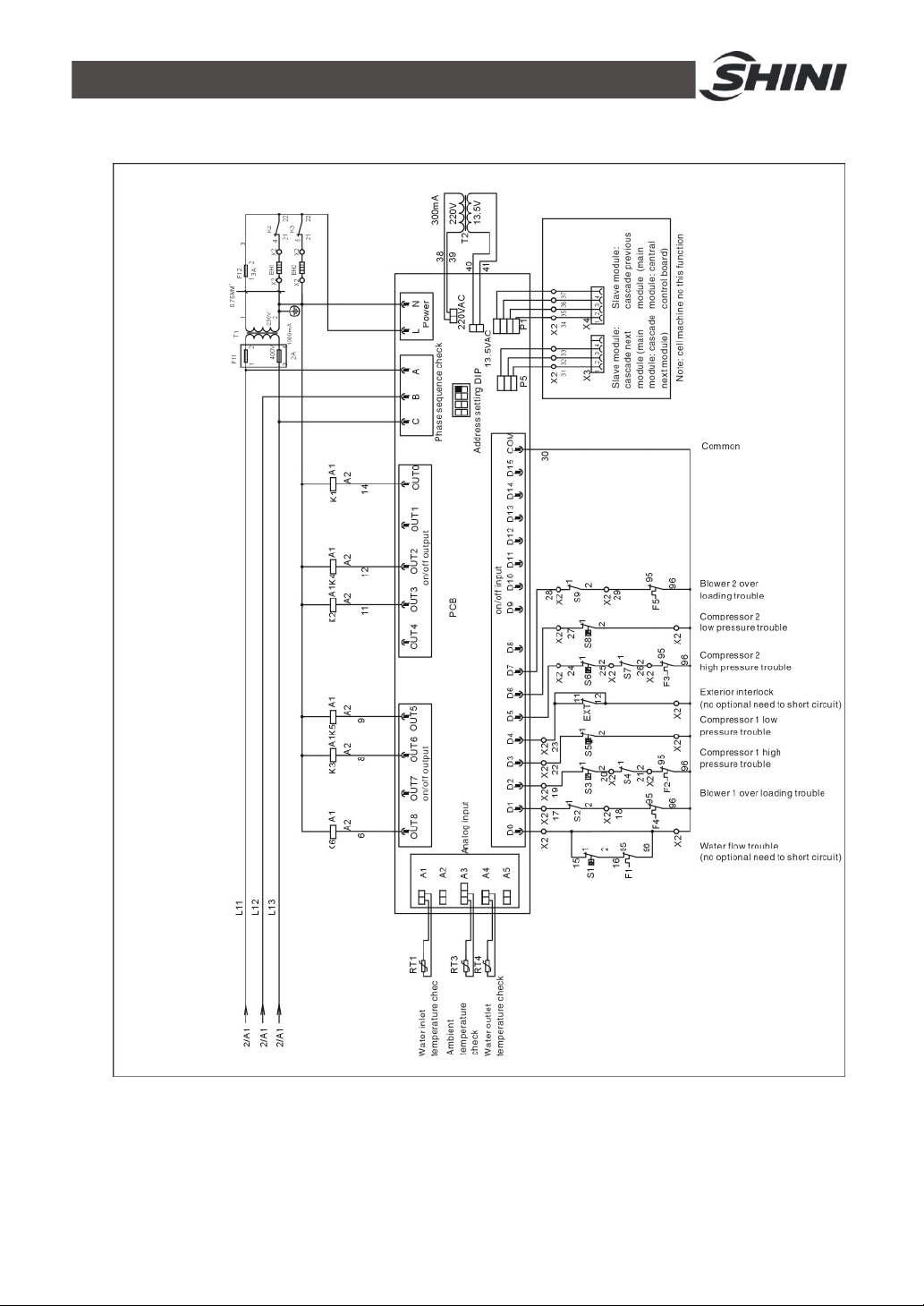
2.2.2 Control Circuit (SICC-60A)
Picture 2-3:Control Circuit (SICC-60A)
25(61)
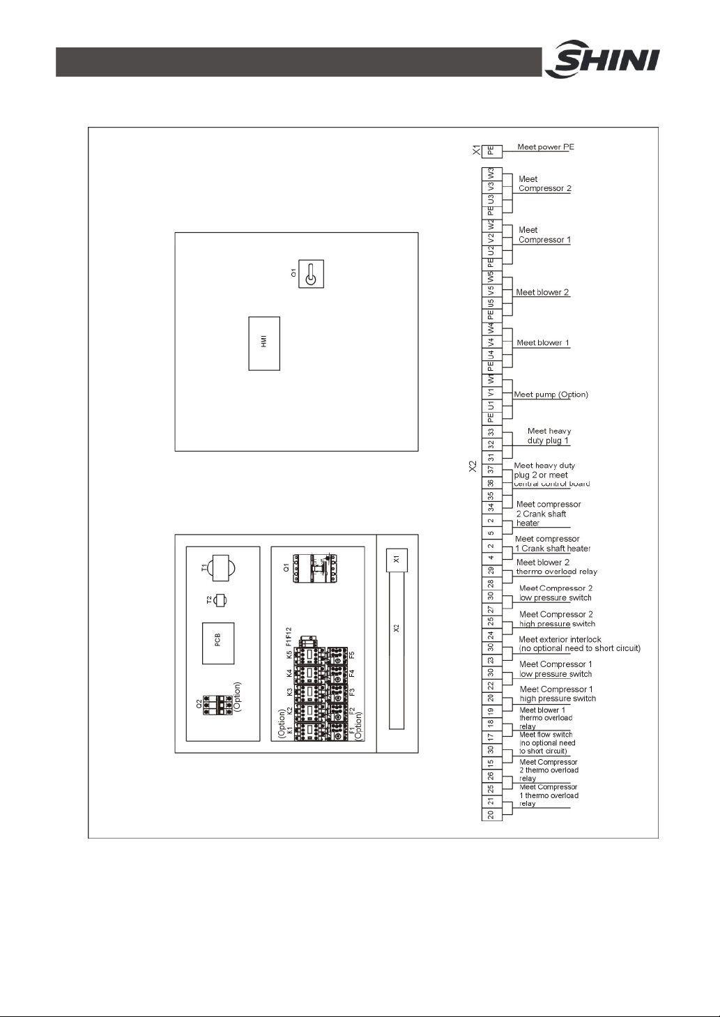
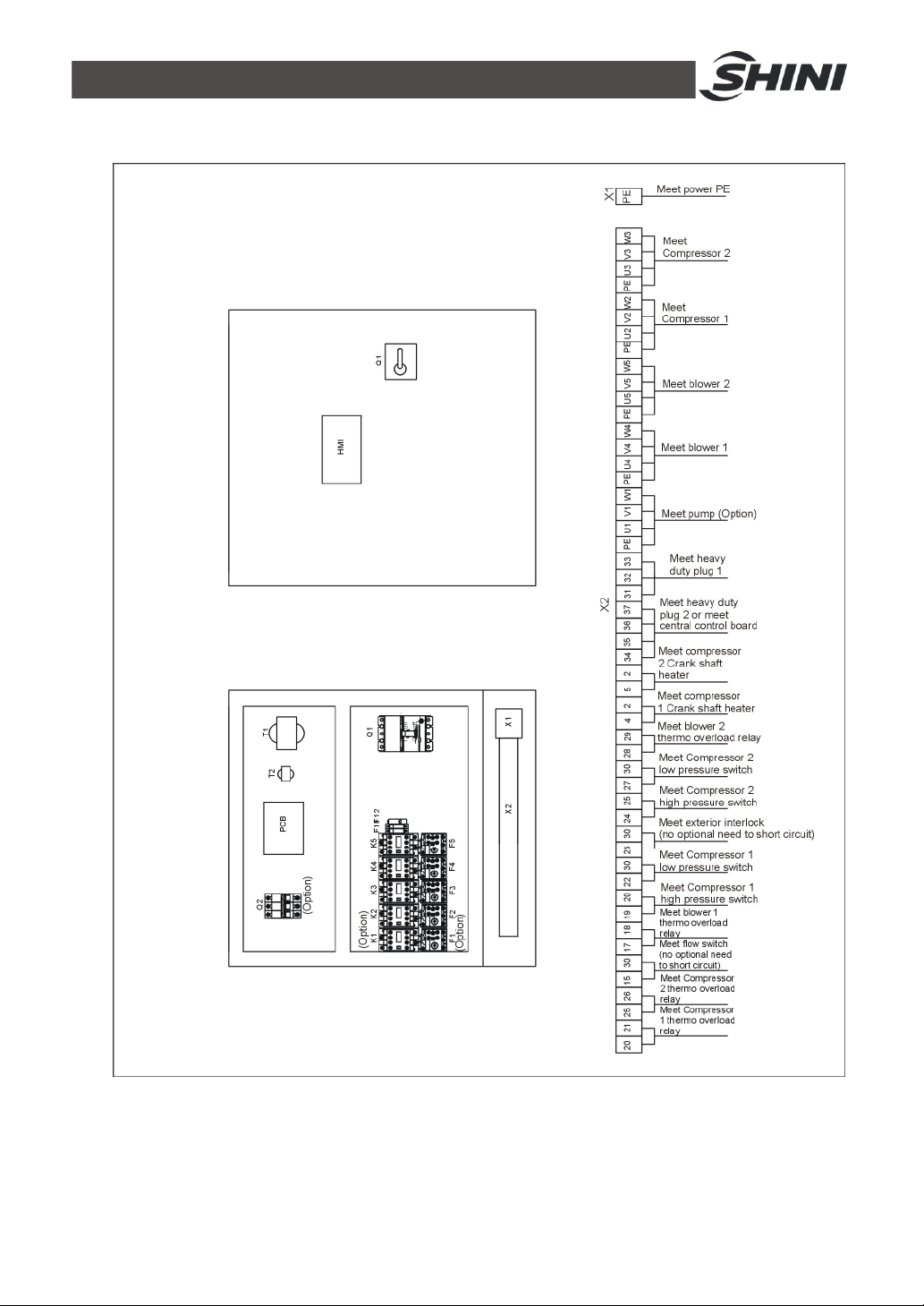
2.2.3 Electrical Components Layout (SICC-60A)
Picture 2-4:Electrical Components Layout (SICC-60A)
26(61)
2.2.4 Electrical Components List (SICC-60A)
Table 2-1:Electrical Components List (SICC-60A)
NO. Symbol Name Specification Part NO.
1 Q1
2 Q2 Circuit breaker
3 K1 Contactor
4 K2 K3 Contactor 230VAC 50Hz YE00331100000
5 K4 K5 Contactor 230VAC 50Hz YE00300000000
6 T1 Transformer IN=400V OUT=230V 1000mA YE70402300000
7 T2 Transformer IN=230V OUT=12V 3VA YE70015300000
8 F1 Overload relay
9 F2 F3 Overload relay 12.5~20A YE01125200100
10 F4 F5 Overload relay 1.25~2A YE01125200000
11 F11 Fuse box 500V 32A 2P YE41032200000
12 - Fuse 2A 18×30 500V YE46002000100
13 F12 Fuse 2A YE41001000000
14 PCB Control board 230VAC 50/60Hz M-02
15 HMI Hmi 230VAC 50/60Hz M-02
16 X1 Terminal board 660V 112A YE61103500000
17 X2 Terminal board 660V 41A YE61040000000
18 - Terminal board - YE61043500000
19 - Terminal board 660V 24A YE61250000000
20 - Terminal board - YE61253500000
21 - Terminal board 660V 24A YE61250000000
22 - Terminal board - YE61253500000
23 X3 X4
24 -
25 M1 Pump motor 400V 50Hz -
26 M2 M3 Compressor 400V 50/60Hz 8.5kW -
27 M4 M5 Fan motor 400V 50/60Hz 0.7kW -
28 EH1 EH2
Circuit breaker 90A YE41109000000
Heavy duty plug
Heavy duty plug
Compressor crankcase
heater
(Optional ) model selection with
pump power
(Optional ) model selection with
pump power
(optional ) model selection with
pump power
4P YE68041000100
Accessories: shipment with
- -
YE68041000000
-
-
-
* means possible broken parts.
** means easy broken part. and spare backup is suggested.
Please confirm the version of manual before placing the purchase order to guarantee that
the item number of the spare part is in accordance with the real object.
27(61)

2.2.5 Main Circuit (SICC-90A)
Picture 2-5:Main Circuit (SICC-90A)
28(61)
2.2.6 Control Circuit (SICC-90A)
Picture 2-6:Control Circuit (SICC-90A)
29(61)
2.2.7 Electrical Components Layout (SICC-90A)
Picture 2-7:Electrical Components Layout (SICC-90A)
30(61)

2.2.8 Electrical Components List (SICC-90A)
Table 2-2:Electrical Components List (SICC-90A)
NO. Symbol Name Specification Part NO.
1 Q1
2 Q2 Circuit breaker
3 K1 Contactor
4 K2 K3 Contactor 230VAC 50Hz YE00331100000
5 K4 K5 Contactor 230VAC 50Hz YE00300000000
6 T1 Transformer IN=400V OUT=230V 1000mA YE70402300000
7 T2 Transformer IN=230V OUT=12V 3VA YE70015300000
8 F1 Overload relay
9 F2 F3 Overload relay 25~36A YE01253600200
10 F4 F5 Overload relay 2~3.2A YE01023200000
11 F11 Fuse box 500V 32A 2P YE41032200000
12 - Fuse 2A 18×30 500V YE46002000100
13 F12 Fuse 2A YE41001000000
14 PCB Control board 230VAC 50/60Hz M-02
15 HMI Hmi 230VAC 50/60Hz M-02
16 X1 Terminal board 660V 112A YE61163500000
17 X2 Terminal board 660V 41A YE61060000000
18 - Terminal board - YE61063500000
19 - Terminal board 660V 24A YE61250000000
20 - Terminal board - YE61253500000
21 - Terminal board 660V 24A YE61250000000
22 - Terminal board - YE61253500000
23 X3 X4
24 -
25 M1 Pump motor 400V 50Hz -
26 M2 M3 Compressor 400V 50/60Hz 13.4kW -
27 M4 M5 Fan motor 400V 50/60Hz 1.04kW -
28 EH1 EH2
Circuit breaker 90A YE41109000000
Heavy duty plug
Heavy duty plug
Compressor crankcase
heater
(optional) model selection with
pump power
(optional) model selection with
pump power
(optional) model selection with
pump power
4P YE68041000100
Accessories: shipment with
- -
YE68041000000
-
-
-
* means possible broken parts.
** means easy broken part. and spare backup is suggested.
Please confirm the version of manual before placing the purchase order to guarantee that
the item number of the spare part is in accordance with the real object.
31(61)

2.2.9 Main Circuit (SICC-120A)
Picture 2-8:Main Circuit 1 (SICC-120A)
32(61)

Picture 2-9:Main Circuit 2 (SICC-120A)
33(61)

2.2.10 Control Circuit (SICC-120A)
Picture 2-10:Control Circuit (SICC-120A)
34(61)

2.2.11 Electrical Components Layout (SICC-120A)
Picture 2-11:Electrical Components Layout (SICC-120A)
35(61)

2.2.12 Electrical Components List (SICC-120A)
Table 2-3:Electrical Components List (SICC-120A)
NO. Symbol Name Specification Part NO.
1 Q1
2 Q2 Circuit breaker
3 K1 Contactor
4 K2 K3 Contactor 230VAC 50Hz YE00331100000
5 K4 K5 Contactor 230VAC 50Hz YE00300000000
6 T1 Transformer IN=400V OUT=230V 1000mA YE70402300000
7 T2 Transformer IN=230V OUT=12V 3VA YE70015300000
8 F1 Overload relay
9 F2 F3 Overload relay 32~40A YE01125200100
10 F4 F5 Overload relay 1.25~2A YE01125200000
11 F11 Fuse box 500V 32A 2P YE41032200000
12 - Fuse 2A 18×30 500V YE46002000100
13 F12 Fuse 2A YE41001000000
14 PCB Control board 230VAC 50/60Hz M-02
15 HMI Hmi 230VAC 50/60Hz M-02
16 X1 Terminal board 660V 41A YE61163500000
17 X2 Terminal board 660V 41A YE61100000000
18 - Terminal board - YE61103500000
19 - Terminal board 660V 24A YE61250000000
20 - Terminal board - YE61253500000
21 X3 X4
22 - Heavy duty plug
Circuit breaker 120A YE41161600000
Heavy duty plug
(optional ) model selection with
pump power
(optional ) model selection with
pump power
(optional ) model selection with
pump power
4P YE68041000100
Accessories: shipment with
manual
YE68041000000
-
-
-
23 M1 Pump motor 400V 50Hz -
24 M2 M3 Compressor 400V 50/60Hz 18.78kW -
25 M4 M5 Fan motor 400V 50/60Hz 0.7kW -
26 EH1 EH2
Compressor
Crankcase Heater
- -
* means possible broken parts.
** means easy broken part. and spare backup is suggested.
Please confirm the version of manual before placing the purchase order to guarantee that
the item number of the spare part is in accordance with the real object.
36(61)

3. Installation and Debugging
Please read this chapter carefully before installation, and you must
install the machine according to the following procedures!
Before installation, please read this chapter carefully and install according to the
procedures as follows!
Install the water chiller near windows or places with good air flowing because
air-cooled central water chiller needs a good heat-releasing condition. If the
water chiller is installed inside the factory, then the surrounding temperature
should not be higher than 35 centigrade and there must have fans to make
air-flow flow fluently or air tube piping the hot air produced by water chiller
outside. If the water chiller is installed outdoor, a veil is needed to cover the top
of the chiller.
3.1 Installation Notice Items
1) Make sure that voltage of electricity matches with the nameplate.
2) Connect the electricity wire and earth wire according to local regulations.
3) Use independent electricity wire and power switch .The diameter of the wire
should not be less than that of electric cabinet’s wire.
4) The end of the electricity wire should be safe and firm.
5) There-phase electricity and five wires are utilized. Connect the power to live
wire, (N) to zero wire and (G) to ground wire.
6) Electric Power distribution demand .Main power voltage: ±10% Main power
frequency: ±2%.
7) Install pipe work system according to scheme of wiring. Protect water chilling
pipes with hear-insulating materials.
8) Make sure that the diameter of the recycling pump pipeline not less than that
of condenser’s connection tube. (Install the inlet or outlet pipeline system
according to the drawing of the assembly line)Large-diameter tube should be
used to connect to cooling water for long-range transmission.
9) The very top of the cooling water recycling loop system must be configured
with self-discharging valve, the lowest with drain valve.
10) Install filter in the cooling water recycing loop due to bad water quality in the
water source and wash the filter at certain times.
37(61)
11) Test if the pipeline leaks after installation. Wrap insulating layer onto the
cooling water recycling pipe to aviod loss of refrigeration capacity and
pipeline leakage.
Power connection must be conducted by professional electricians!
Do not change the circuit of the water chiller without our company's
authority. If the machine is damaged by unauthorized change we are not
responsible for this.
3.2 Select Installation Site
1) No heat source existence nearby to acoid efficiency reduction due to
absorbing hot air.
2) No impact imposed by high temperature, vapor or oil stain.
3) Avoid being spattered by water vapor when choosing installation site near
cooling water tower, so to avoid any short ciruit or creepage.
4) Proper ventilation without hindrance for air inhaled exhaled.
5) No existence of inflammable substance.
6) When using concrete bearing platform,the platform must be firm and flat.
Install shockprooof mat in the bolt of bearing platform if necessary.
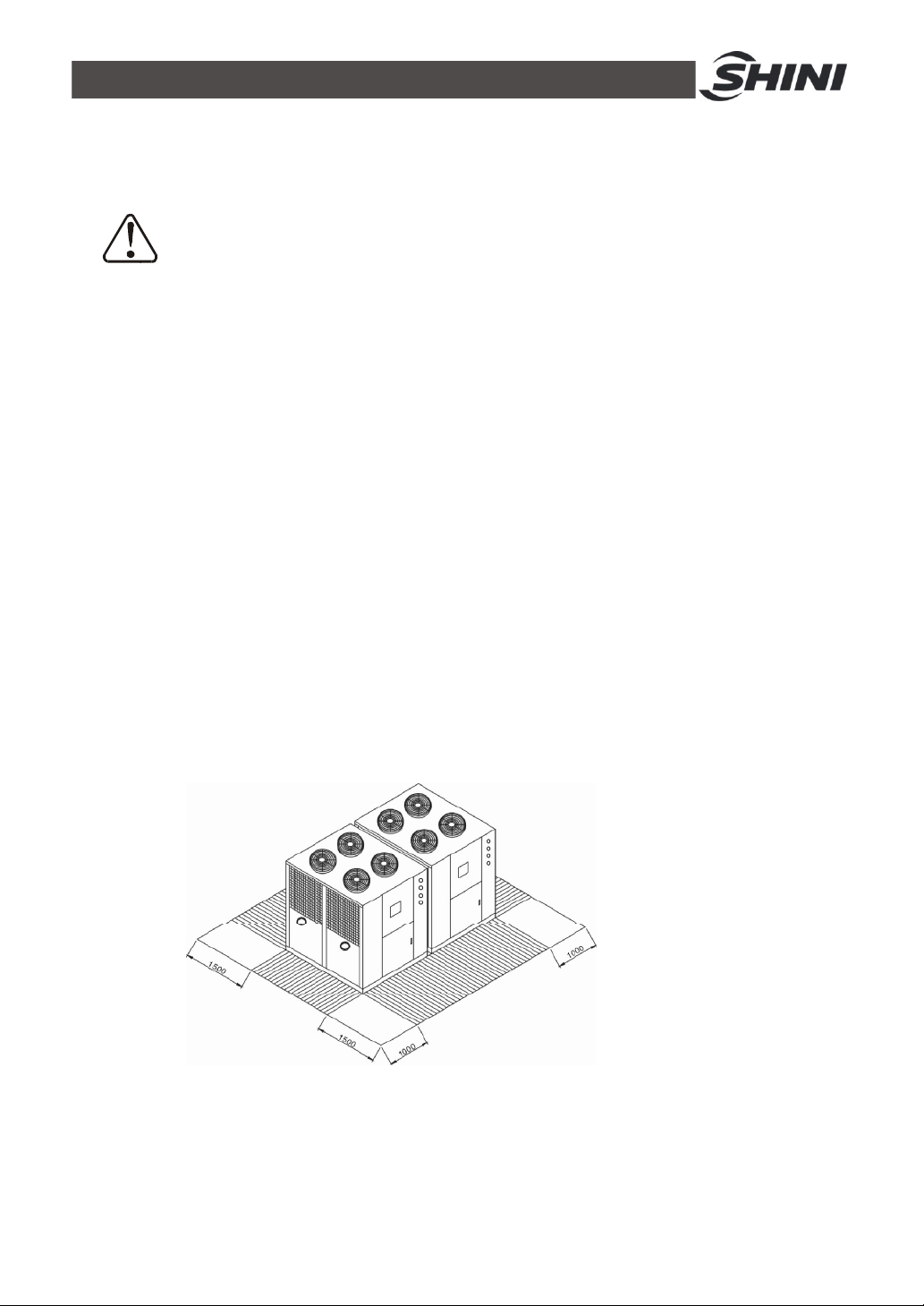
7) Set apart some service space.Space ranges are recommended as shown in
figure 3-1.
Length unit: mm
Picture 3-1:Installation Space
38(61)

3.3 Bearing Platform
1) The unit should be installed on concrete or steel structure bearing platform
that is firm and the surface of the baring platform should be smooth and flat.
The in tensity of the platform should hold the whole unit, if the inten sity is not
strong enough, it is easy to cause vibration and noise.
2) The surface of the concrete base platform normally has compo as horizontal
ornament and with waterproof treatment,the surrounding of it should have
drainage sink placed, and the slope angle should be no less than 0.5%,and
the slope should lead to drainage outlet.
3) Inorder to maintain quiet operation and prevent the vibration and noise
transmission from interfering the under floors,the absorber should be laid
between the unit base and base platform. Please maintain horizontal when
install the unit and mount anti vibration pad when it is necessary.
4) Inorder to keep connection pipe from being twisted to crack by earthquake,
typhoon, or by long time running caused movement. The fixation method
should be taken into consideration, refers to following examples for platform
installation and fixation:
Picture 3-2:Platform Installation
1. Photo 3-2 the platform size is for module unit, pay special attention to
the real location and size of installation holes.
2. When adopts photo 3-3 showed fixation way, keep bearing bolt holes
for platform and its absorber as photo 3-2 showed installation hole
location.
39(61)

3.4 Hanging and Transporting of the Unit
1) Propose plans of hanging and transporting before practise, including entering
date for each unit. Dimensions of appearance. Weight, path, reserved holes,
hanging and transporting device as well. Figure 3-1 shows the details.
Items Check points
Path
Unload
Transporting
Transporting
Path adjustment Adjust with the wall,floor to facilitate transporting.
Others
1. Check aisle, stair gate and transporting path.
2. Check roof,base room and hanging path.
1. Check the weight of the unit.
2. Prepare unload devices.
3. Check the temporary laying place and keep the unit clean.
1. If the large-scale machine can be decomposed, then decompose
it and transport each part respectively and then combine them
finally.
2. If the large-scale machine cannot be decomposed, then dig hole
in the wall or earth to transport it.
Arrangenent of Labor and hanging device; problems of woker and
unit safety.
2) According to safety command, when hanging and transporting units, assign
special person to direct and there must be warning and precaution measures
to ensure safety of people and machines.
3) Consider the weight of the unit. Take woven belt as hanging device and add
bearing articles to avoid damage to metal board.Keep horizontal or vertical
state. It is forbidden the unit inclined by over 30 degrees.
4) Protect the unit from being cut or deformation.Place protective mat or wood
poles in the contact places between woven belt and the unit.
Picture 3-3:Hanging and Transporting of the Unit
40(61)

3.5 Water System Tubing
1) The inlet /outlet pipes and valves of the unit should have itselves insulated.
The outside parts should have protective veil to prevent the thermo lost and
dewfall happen and this brings no impact on building structure and
anti-freezing when it is in winter.
2) To ensure that there is enough water in the water-side exchanger and
pipeline system so to avoid its internal icy water comes to freeze up, over low
pressure and bad oil return rate within system when refrigerating, there after
lead to the failure of the compressor and burn down to the worse. So water
flow switch should be mounted at the water outlet side and was controlled
chainly with compressor.
3) If closed circuit type water distribution pipelines are used, an inflated water
tank should be placed higher by at least 1m than top of the whole set of water
distribution pipelines to buffer the water volume's expansion or contraction
and the isolated backup water pressure to water distribution pipelines'
influence. Check valve should not be mounted at the outlet of inflated water
tank so to avoid pipe leakage or crack.
4) The pump of the unit should be mounted at the water inlet of the main module
machine.
5) Avoid air left in the water system, Install automatic exhaust steam
dischanging valve in the highest position of all the water distribution pipes.
The horizontal pipe of the water distribution system must be laid with an
inclination of 1/250.
6) There should have flexible joint, flange joint and break valve for later
maintenance.
7) There mameter and pressure meter should be set in the inlet and outlet of the
unit to facilitate daily check.
8) There are same directions way and opposite direction way to install the water
pipe of the module unit.
41(61)
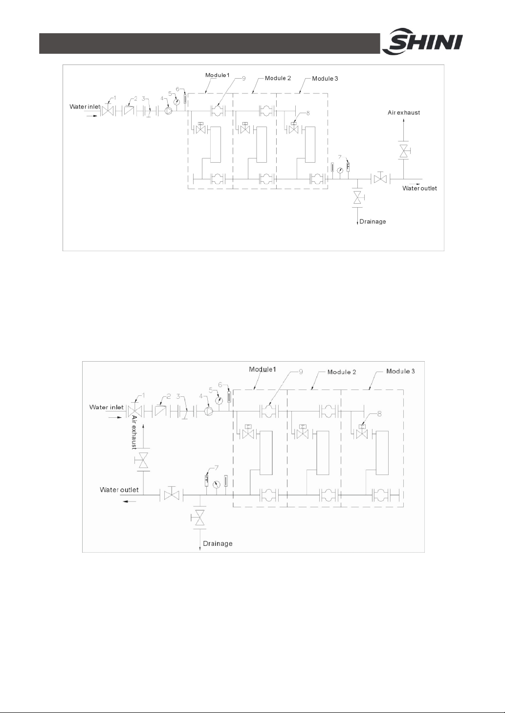
Names of Parts:
1. Stop valve 2. One way valve 3. Y type filtration valve
4. Pump 5. Pressure meter 6. Thermometer
7. Flowmeter 8. Solenoid valve 9. Rubber soft pipe
Picture 3-4:Same Direction Way 1
Names of Parts:
1. Stop valve 2. One Way valve 3. Y type Filtration valve
4. Pump 5. Pressure meter 6. Thermometer
7. Flowmeter 8. Solenoid valve 9. Rubber soft pipe
Picture 3-5:Same Direction Way 2
42(61)
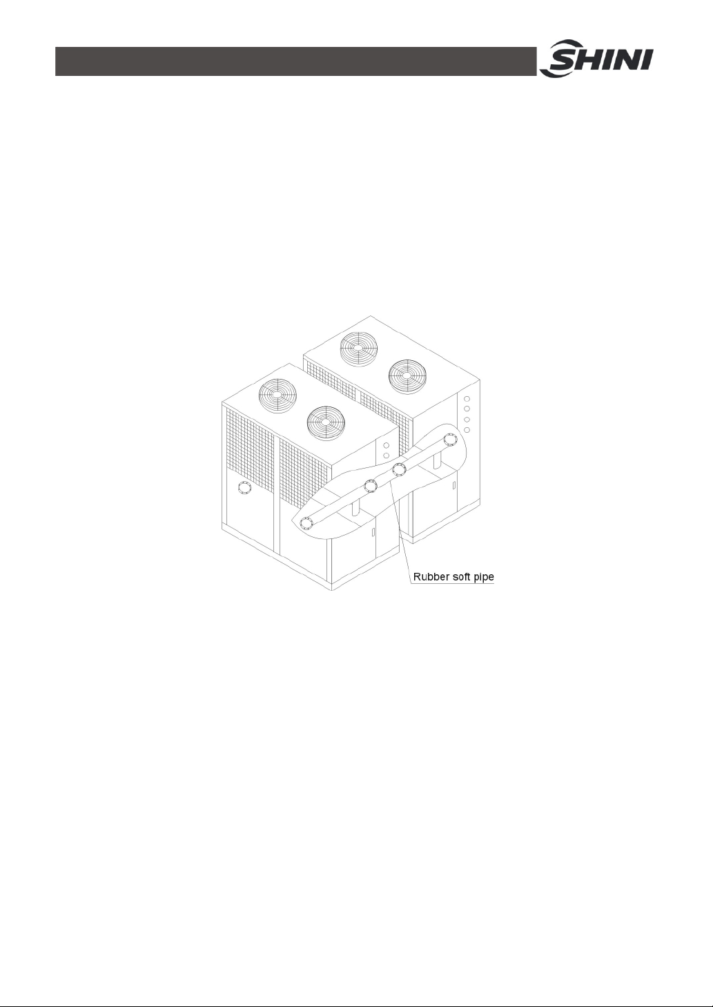
3.6 Combined Installation of Modules
1) Disassembly the sideplates around the machine, calibrate the cooling water
inlet to combine the modules. Use rubber soft pipe to connect the module's
chilling water pipe.
2) The non-exist end of the cooling water pipe should be fixed by flange.
3) Refers to wiring diagram to tandem the communication line to next
submodule, the communication line of which tandems to next submodule
thereby.
Picture 3-6:Combined Installation of Modules
3.7 Essentials for Electric Wiring
1) The electricity supply should use special branch circuit.
2) Wiring work should be conducted according to relevant national electric
standards and grounding.
3) Refer to wiring diagram to conduct wiring work. Lock up every contact screws,
do not let them loosen.
4) The voltage has to be stable when in operation, take all the voltage down fall
into consideration, the unit working voltage should maintain at±10% within
rated voltage. Over high or over low voltage will bring bad effect to the unit.
5) The length of the power cable must ensure the voltage gap value between
the head and tail of cable be less than ±2% within rated voltage, if the length
can not be shorter. Then enlarge the diameter of the cable.
43(61)

6) The wiring connection between power and unit should be conducted
according to electrical regulations with good insulation, after the unit being
connected to the power; the terminals of the electrical components resistance
should be at least more than 3MΩ.
7) Inorder to avoid the damage to those electrical devices such as transformer
or wiring due to short circuit, and helps to separately control the start/stop of
every compressor, every incoming cable needs to equip proper amount of
non-fuse breaker. Showed in the following photo:
8) Inorder to ensure personal safety, to avoid electric shock due to creepage the
housing of the unit needs to have a good grounding protective device to avoid
electric shock, all the work should be carried out by strictly follow the
electrical regulations.
Picture 3-7:Essentials for Electric Wiring
3.8 Power Connection
Check the specification of the electricity supply to see if it matches with that of
the demand. For SICC-A series, the specification of power is AC3Φ400V type.
We can also manufacture according to client’s special demand. The ground wire
must be connected to when connect to the power.
Ensure the power switch's shut-off condition befor being connected to
power wire.
44(61)

4. Operation Guide
4.1 Control Panel
Picture 4-1:Control Panel
4.2 The Make Up and Layers of the Display Interface
4.2.1 The Make up of the Display Interface
a Startup display “welcome”
b Main working interface
c System function selecting interface
d 1 Time setup interface
1) Set system time
2) Set auto start/stop time
e System parameters setup interface
1) System configuration
2) Tthe setup for unit running
3) The setup of system parameters
f Iinquiry module parameter selecting interface
1) Inquiry every module's running condition interface
2) Inquiry every module's detecting temp. interface
3) Inquiry every module's faults status interface
4.2.2 Interfaces Show
45(61)
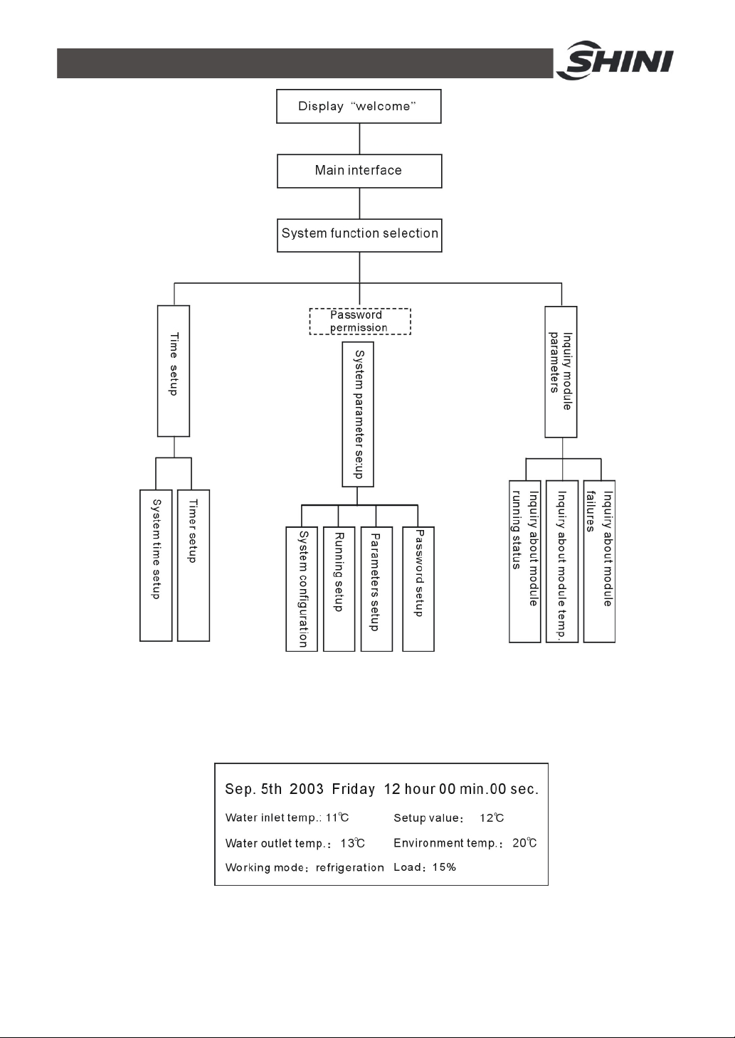
Picture 4-2:Interfaces Show
4.3 Main Working Interface
4.3.1 Interface Demonstration
Picture 4-3:Main Working Interface
4.4 Selecting Interface of System Function
46(61)
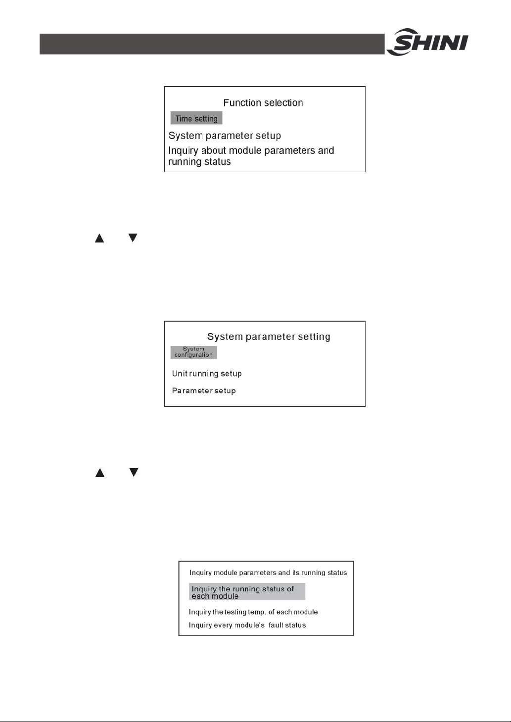
4.4.1 Interface Demonstration
Picture 4-4:Selecting Interface of System Function
4.4.2 Interface Operation
Press “ ” or “ ” to select different functions, press “menu” key to enter selected
functions, press“return”key to back to main working interface.
4.5 System Parameter Setup Interface
4.5.1 Interface Demonstration
Picture 4-5:System Parameter Setup Interface
4.5.2 Interface Operation
Press " " or " " key to select different functions, press "menu" key to enter into
selected function, press "return" key to back to main working interface.
4.6 Inquiry Parameters of the Module
4.6.1 Interface Demonstration
Picture 4-6:Interface Demonstration
47(61)

4.6.2 Interface Operation
Press " " or " " key to select different functions, press "menu" key to enter
selected function, press "return" key to back to main working interface.
4.7 System Time Setup
4.7.1 Interface Demonstration
Picture 4-7:Interface Demonstration
4.7.2 Interface Operation
Press " " or " " key to select "year" "month" "day" "date" "hour" and "min"
settings, press">"or"<"key to change the value of selected items, press"eturn"
key to back to time setting interface.
4.8 System Configuration
4.8.1 Interface Demonstration
Picture 4-8:System Configuration
4.8.2 Interface Instruction
To set up the parameters for system configuration
1) Module quantity: set up the number of component module, setup range: 1-15.
2) Pump: configured with build-in pump or outfitted pump. When displays
"available", it indicates build-in pump and when displays "not available", it
indicates outfitted pump.
3) Hot pump: configured modules are single cooling unit and hot pump unit.
When displays “available”it indicates hot pump unit and when displays "not
available" it indicates single cooling unit.
48(61)

4) Auxiliary heat 1: check if there is auxiliary heat in module configuration 1#.
When displays “available”it indicates module 1# has been connected to
auxiliary heat and when displays "not available" it indicates module 1# has no
auxiliary heat connection.
5) Auxiliary heat 2: check if there is auxiliary heat in module configuration 2#.
When displays "available" it indicates module 2# has been connected to
auxiliary heat and when displays "not available" it indicates module 2# has no
auxiliary heat connection.
Note!
There is no heating function for this machine.
6) Module number: select the module that needs online function.
7) Setup online function: check to see if it needs to be online. When displays
"start" , it indicates this module is online, and works effectively within the unit
and when displays "forbidden", it indicates that this module is offline and
works invalid within the unit ( if some module has faults or due to some other
reason, it can not be put into the unit to work, its online function can be
forbidden.
Note!
The online function of module 1# can not be“forbidden”
4.8.3 Interface Operation
Press " " or " " key to select different functions, press ">" or "<" return key to
back to time setting interface.
49(61)

4.9 Unit Running Settings
4.9.1 Interface Demonstration
Picture 4-9:Unit Running Settings
4.9.2 Interface Operation
Press " " or " " key to select different function, press ">" or "<" key to change
the value of selected items, press "return" key to back to the time setting
interface.
4.10 Parameter Setting
4.10.1 Interface Demonstration
Picture 4-10:Parameter Setting
4.10.2 Interface Operation
Press" " or " " key to select different functions, press ">" or "<" key to change
the value of selected items. Press “return”key to back to time setting interface.
Press " " or " " key to select the setup items and it supports screen scrolling.
Press“menu”key to resume the above parameters back to default values.
50(61)

4.11 Unit Running Setup
4.11.1 Interface Demonstration 1
Picture 4-11:Unit Running Setup 1
4.11.2 Interface Demonstration 2
Picture 4-12:Unit Running Setup 2
4.11.3 Interface Instruction
Inquiry each module's running status
1) There are 3 status namely open, close and no connection for each module,
the no connection status is not displayed.
2) Inquiry each module's detailed running parameters by pressing " " " " key
to select module firstly, then press "menu" key to access into every module's
running status parameters. As enterring into interface demonstration 2.
3) It displays the inquired module number firstly, then folllowing below displays
its module running status.
4) When the screen pops up "waiting for defrosting "or" defrosting", thetop right
corner of the first line displays its status and there is no display when in other
condition.
4.11.4 Interface Operation
Press " " " " key to select different module(interface demonstration 1), press "
return" key to back to inquiry module parameter interface. Press "menu" key to
enter into running status nquiry interface.
51(61)
4.12 Inquiry Module Temperature
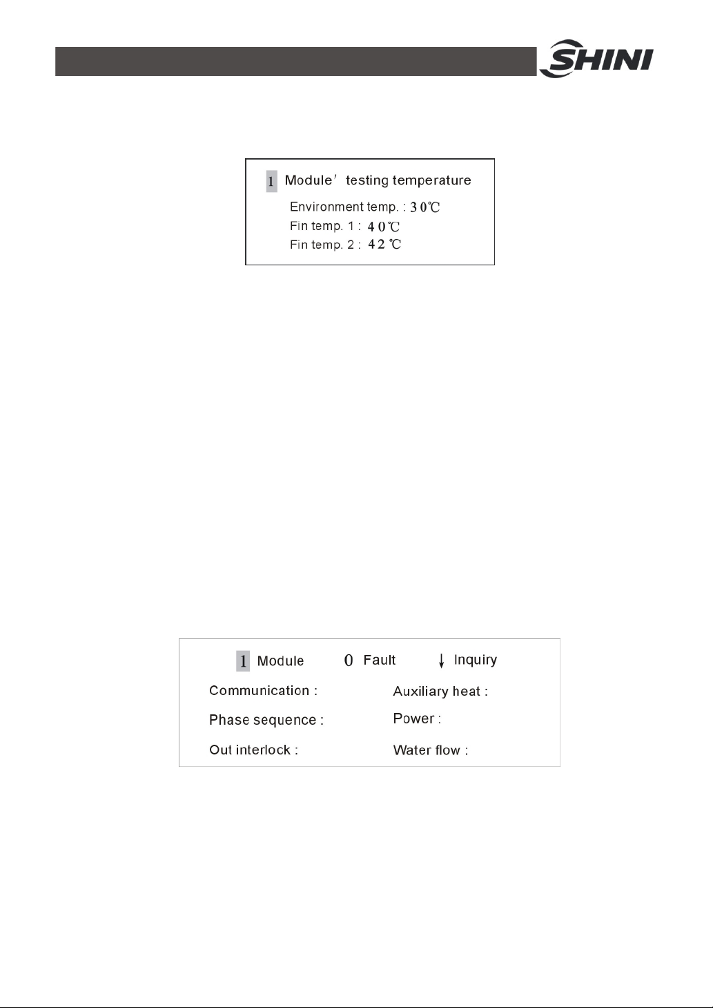
4.12.1 Interface Demonstration
Picture 4-13:Inquiry Module Temperature
4.12.2 Interface Instruction
The first line displays the inquiry module number, the rest displays the elated
temp. Value from module testing.
4.12.3 Interface Operation
Press ">" or "<" key to select different module(module number is in the range of
network module number), press “return” key to back toinquiry module parameter
interface.
4.13 Inquiry Faults
4.13.1 Interface Demonstration
4.13.1.1 Sub-interface 1
Picture 4-14:Sub-interface 1
4.13.1.2 Sub-interface 2
52(61)

4.13.1.3 Sub-interface 3
Picture 4-15:Sub-interface 2
Picture 4-16:Sub-interface 3
4.13.2 Interface Instruction
1) For every module fault inquiry,it consists of 3 sub-interfaces.
2) The first line displays the module number and the faults number.
3) Support page up/down to inquiry fault.
4) Communication: indicate the status between the module and central control
board, when it displays "fault", it means communication failure.
5) For other faults' instruction, please refer to function instruction book.
4.14 The Configuration of Module Unit
Shini SICC-A series adopt modular design with three unit modules including
SICC-60A, SICC-90A and SICC-120A, each of them can be used as a unit
independently or combine together to meet system load based on actual
operations. SICC-A series modular device is capable of automatically switching
on or off unit modules to save energy as system load varies. Shini is able to fare
15 unit modules combination to reach the maximum cooling capacity of 1800kW.
Users can follow steps below to combine these unit modules:
1) Pipeline Connection of Chilled Water
53(61)

In modularized configuration for chilled water circuit, there are two methods of
connection: reversed return and direct return. In reversed return connection
chilled water flow distance through every unit module is the same while in direct
return the flow distance is not equal. Flow distance in reversed return has the
same resistance and water flow while flow distance in direct return has the
different resistance and water flow. Generally, chilled water pipeline connection
adopts reversed return type.
Chilled water inlet and outlet in SICC-A unit module adopt 5 inch flange as joint
face. Use 5 inch rubber connecting flange can complete the combination of two
unit modules of pipeline. Both flange and rubber connecting flange are national
standard parts and they are conveniently to purchase.
2) Control Line Connection of Host/Sub Modules
Complete control line connection following chilled water pipeline connection.
No.1 terminal in host PCB connects display control panel. No.2 terminal
connects No.1 terminal of sub 1# module and No.2 terminal of sub 1#module
connects No.1 terminal of sub 2# module. Complete connection in sequence as
number of unit module increases. (Note: four lines in No.1 terminal and three in
No.2. When connecting No.1 and No.2, the black line in No.1 terminal is free of
connection).
3) Control Setting
Complete control setting following control line connection. Firstly is the setting of
each unit module address, which can be finished by controlling DIP switches on
PCB. Address range is from 1 to 15. On the using of module combination,
display control panel connects 1# module to centrally control all unit modules in
the system. Refer picture below for DIP switch setting (Black area indicates
54(61)

switching DIP to “ON”, as shown in number “4”).
address
Module
DIP1 DIP2 DIP3 DIP4
number
OFF OFF OFF OFF Keep as spare
Must have module 1# which the
OFF OFF OFF ON 1
OFF OFF ON OFF 2
OFF OFF ON ON 3
OFF
OFF
OFF
OFF
ON OFF OFF OFF 8
ON OFF OFF ON 9
ON OFF ON OFF 10
ON OFF ON ON 11
ON ON OFF OFF 12
ON ON OFF ON 13
ON ON ON OFF 14
ON ON ON ON 15
ON OFF OFF 4
ON OFF ON 5
ON ON OFF 6
ON ON ON 7
shared water pipe detecting and
devices has all been connected to
Remark
55(61)

Next comes the setting on the control panel. Select and press buttons in
sequence: Function selection—System param. Setting—Password
(input)—System configuration:
1. Network module number: setting the number of modules composing system.
2. Water pump: equipped with the built-in pump or external pump. ON means
built-in pump and OFF means external pump.
3. Heat pump: units include single cool and heat pump models. ON means it is
heat pump and OFF single cool.
4. Auxiliary heat 1: indicate whether 1# module is equipped with auxiliary heat.
ON means connecting one and OFF no connecting.
5. Auxiliary heat 2: indicate whether 2# module is equipped with auxiliary heat.
ON means connecting one and OFF no connecting.
6. Module number for modularized configuration: module selected to be
ONLINE or not (set the module to be ONLINE running).
7. ONLINE setting: set the module to be ONLINE running. ON means module
online and it is activated in the unit while OFF means module offline and it is
idle in the unit (module is not applied to the unit for any fault, set it offline). 1#
module can not be OFFLINE.
56(61)
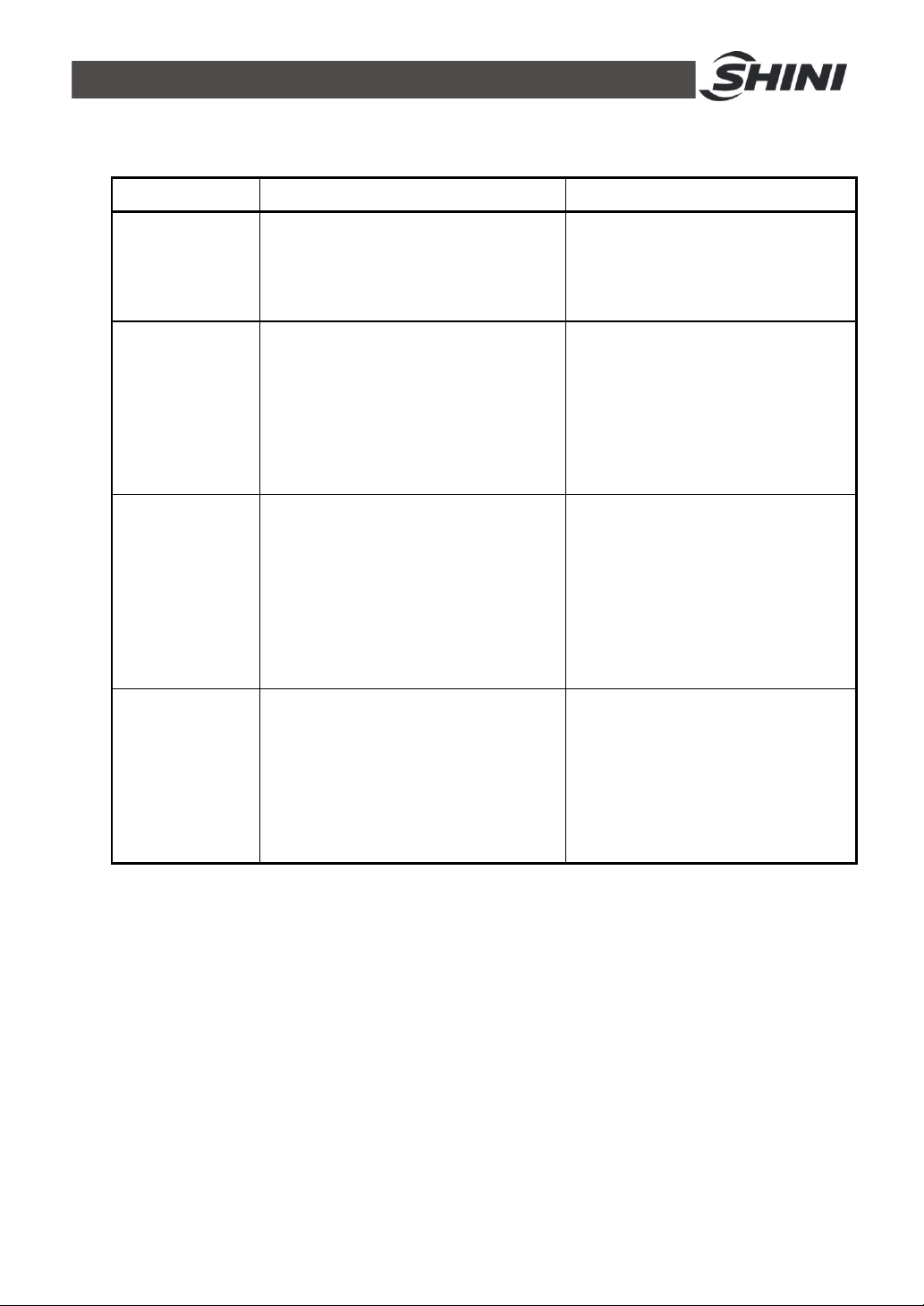
5. Trouble-shooting
Failures Possible reasons Solutions
1. NO power
Fan, pump and
compressor can
not start up
Pump runs but
compressor can
not start.
Compressor
stops immediately
after it starts.
Big lnlet/outlet
water
temperature
difference and
over low
low-pressure
(when cooling
flow runs).
2. Power switch jumps
3. Power fuse is burnt.
4. Pump overloads.
1. The setup value for temperature
switch is too high.
2. Failure in temperature switch.
3. Compressor overloads.
4. The setup temperature for
compressor is too low (for heat flow)
5. No restore after the protective switch
jumps.
1. Air inlet or outlet gets hindered.
2. Condenser is dirty.
3. Bad ventilation due to bad landform.
4. Fan fails.
5. The cooling water valve has not been
opened.
6. Overlow cooling water auantity.
7. Cooling medium leaks.
8. Compressor overloads.
1. Pipeline blocks due to wrong pipeline
switching
2. Too much gas in the pipeline.
1. Wait for power recovery
2. Check the power and make it ormal
3. Change power fuse
4. Check and reset or repair the
failure.
1. Edit the value.
2. Check or change.
3. Check and reset.
4. Edit the value (for heat flow)
5. Check and reset.
1. Remove the hindering articles.
2. Wash and clean.
3. Improve gy client.
4. Check and repair.
5. Open the valve.
6. Check the pump to remove the tube
air.
7. Repair the leak spot.
8. Edit setup value.
1. Check the valve of the pipeline and
attachments.
2. Exhaust the air in the pipeline.
57(61)
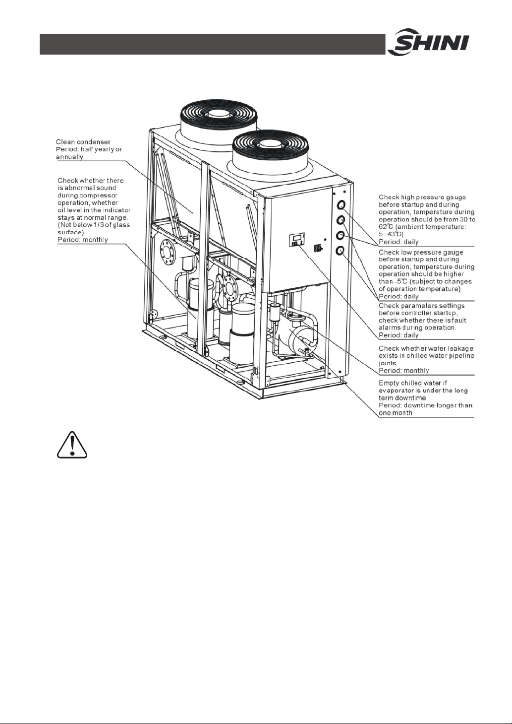
6. Maintenance and Repair
Note!
All repairing work must be conducted by professional person to avoid
personal injury and damage of machine.
Matters require attention when do machine maintenance are as follows:
1) Do not stop the machine via cut the power supply unless emergncyoccurs.
2) When failure occurs and machine stops, press the main power switch (alarm
light will go out). Check the failure and do not start the machine before
trouble-shooting.
3) Check the system periodically to expand the system's lifespan and avoid
safety accident.
4) Dispose the water because water with high PH will accelerate the rust to the
copper tube and decrease the heat exchanger's lifespan. Keep the water PH
in the scale of 7.0~8.5.
58(61)

5) Keep the unit dry, clean and ventilative.
6) The daily operation, unit management, maintenance and repair must be
conducted by professional technicians. (Danger exists when dissembling and
checking the unit, please take care!)
6.1 Daily Repair and Check Items
1) Operation, startup, stop, maintenance and repair works must be conducted by
professional technicians to expand the unit's lifespan.
2) Daily check includes recording indoor/outdoor temperature, cooled water
temperature, voltage, current for further reference, such as adjustment and
maintenance.
3) Clean the appearance of the unit.
6.2 Monthly Periodical Checking Items
1) Check if the screws loosen.
2) Clean indoor air conditioner box or filter of cool air blower.
3) Check if the joint of the pipelines leaks.
4) Check the wire to see if there is any damage, the connection is firm and
whether contact points are burnt.
5) Check the compressor oil level (notice there is no-oil-indicating window).
6) Check the cooling water system to see if it is air proof. If there is air, please
exhaust it.
7) Check the cooling medium pressure.
8) Clean the dirt of the condenser.
9) Check the inflated tank to see if the supplementary feed water is normal.
6.3 Monthly Periodical Checking
1) Check according to monthly check items.
2) Check the insulation resistance of the compressor to see if it is above 10MΩ.
3) Check high voltage switch and low voltage switch to see if their trip off values
are normal.
59(61)
6.4 Maintenance Schedule
6.4.1 About the Machine
Model SN Manufacture date
Voltage Ф V Frequency Hz Power kW
6.4.2 Installation & Inspection
Check if the pipe are connected correctly
Check if the pipe has any leakage
Check if the sealed joint has any crack
Electrical component installation
Voltage: V Hz
Fuse melting current: 1 Phase A 3 Phase A
Power phase sequence check
6.4.3 Daily Checking
Check the function of switches.
Check all wires of the machine.
Check whether pressure gauges are accurate.
Check whether compressor temperature is normal.
Check whether cooling water circulation is normal.
6.4.4 Weekly Check
Check if the joint point is loose.
Check chiller's protective alarming function.
Check whether set point of hi-low pressure switch is normal.
6.4.5 Monthly Check
Check the circulated pipe to seeif there is any leakage.
Check whether there are bubbles in liquid indicator.
Check whether there is abnormal sound in pump.
Check whether there is scale formation in tank.
6.4.6 Trimonthly Checking
Check whether condenser is under blockage.
60(61)

6.4.7 Check Half-yearly
Check and clean filter and expansion valve.
Check the whole machine condition.
Clean condenser.
6.4.8 Yearly Checking
Check whether the contactor is normal.
6.4.9 3 year Checking
PC board renewal.
No fuse breaker renewal.
61(61)
 Loading...