

Page 1

SAL-330/360
Self-contained Hopper Loader
Date: Jan, 2016
Version: Ver.B
Page 2

Page 3

Content
1. General Description ..................................................................................... 7
1.1 Coding Principle ...................................................................................... 7
1.2 Main Features: ........................................................................................ 7
1.3 Technical Specifications .......................................................................... 9
1.3.1 External Dimensions ...................................................................... 9
1.3.2 Mounting Base Specifications ........................................................ 9
1.3.3 Loading Capacity ......................................................................... 10
1.3.4 Specification List .......................................................................... 10
1.4 Safety Regulations ................................................................................ 11
1.5 Exemption Clause ................................................................................. 12
2. Structure Characteristics and Working Principle .................................... 13
2.1 Working Principle .................................................................................. 13
3. Assembly Drawing ..................................................................................... 15
3.1 Assembly Drawing (SAL-330) ............................................................... 15
3.2 Parts List(SAL-330) .......................................................................... 16
3.3 Assembly Drawing (SAL-360) ............................................................... 18
3.4 Parts List(SAL-360) .......................................................................... 19
4. Electrical Circuit Diagram .......................................................................... 21
4.1 Electrical Diagram ................................................................................. 21
4.2 Electrical Components Layout and Terminal Connection Diagram ......... 22
4.3 Electrical Components List .................................................................... 23
4.4 Main Electrical Components Description .................................................. 24
4.4.1 AC Contactor ............................................................................... 24
5. Installation and Debugging ........................................................................ 25
5.1 Installation of SAL-330 / 360 .................................................................... 25
5.1.1 Installation Methods of SAL-330 / 360 ......................................... 25
5.1.2 Installation Methods of SAL-330/360 Optional Collective Hopper
SCH-6L.................................................................................................. 26
5.1.3 Installation Methods of SAL-330/360 Optional Proportional Valve
SPV-U ................................................................................................... 27
5.2 Installation Space ................................................................................... 28
3(40)
Page 4

6. Application and Operation ......................................................................... 29
6.1 Control Panel ......................................................................................... 30
6.2 Function Setup ....................................................................................... 31
6.2.1 Setup ........................................................................................... 31
6.2.2 Actions ......................................................................................... 32
6.2.3 Parameter List ............................................................................. 35
6.2.4 Other Settings .............................................................................. 35
7. Troubleshooting ......................................................................................... 36
7.1 Troubleshooting for SAL-330/360 Series .................................................. 36
8. Maintenance and Repair ............................................................................ 37
8.1 Filter Screen ........................................................................................... 37
8.1.1 Service Life of Product Key Part .................................................. 38
8.2 Hopper ................................................................................................... 38
8.3 Cloth Filter .............................................................................................. 38
8.4 Blower .................................................................................................... 39
8.5 Maintenance Schedule ........................................................................... 40
8.5.1 About the Machine ....................................................................... 40
8.5.2 Check after Installation ................................................................ 40
8.5.3 Daily Checking ............................................................................. 40
8.5.4 Weekly Checking ......................................................................... 40
8.5.5 Monthly Check ............................................................................. 40
Table Index
Table 1-1: Specification list .............................................................................. 10
Table 3-1: Parts list(SL-330) ............................................................................ 16
Table 3-2: Parts list(SL-360) ............................................................................ 19
Table 4-1: Electrical components list ............................................................... 23
Table 6-1: Control panel description ................................................................ 29
Picture Index
Picture 1-1:External dimensions....................................................................... 9
Picture 1-2:Mounting base specifications ......................................................... 9
Picture 1-3:Loading capacity .......................................................................... 10
4(40)
Page 5

Picture 2-1:Working principle of SAL-330/360 ............................................... 13
Picture 3-1:Assembly drawing (SAL-330) ...................................................... 15
Picture 3-2:Assembly drawing (SAL-360) ...................................................... 18
Picture 4-1:Electrical diagram ........................................................................ 21
Picture 4-2:Electrical components layout and terminal connection diagram .. 22
Picture 4-3:Contactor ..................................................................................... 24
Picture 5-1:Installation methods of SAL-330/360 ........................................... 25
Picture 5-2:Installation method of optional SCH-6L........................................ 26
Picture 5-3:Installation method of optional SPV-U ......................................... 27
Picture 5-4:Installation space ......................................................................... 28
Picture 6-1:Control panel ............................................................................... 29
Picture 8-1:Filter screen ................................................................................. 37
Picture 8-2:Cloth filter ..................................................................................... 38
5(40)
Page 6

6(40)
Page 7
1. General Description
Please read through this operation manual before using and installation to
avoid damage of the machine and personal injuries.
The SAL-330/360 series use a high-speed motor in this lightweight and compact
unit. With superior suction power and easy installation. It is particularly suitable
for conveying new materials.
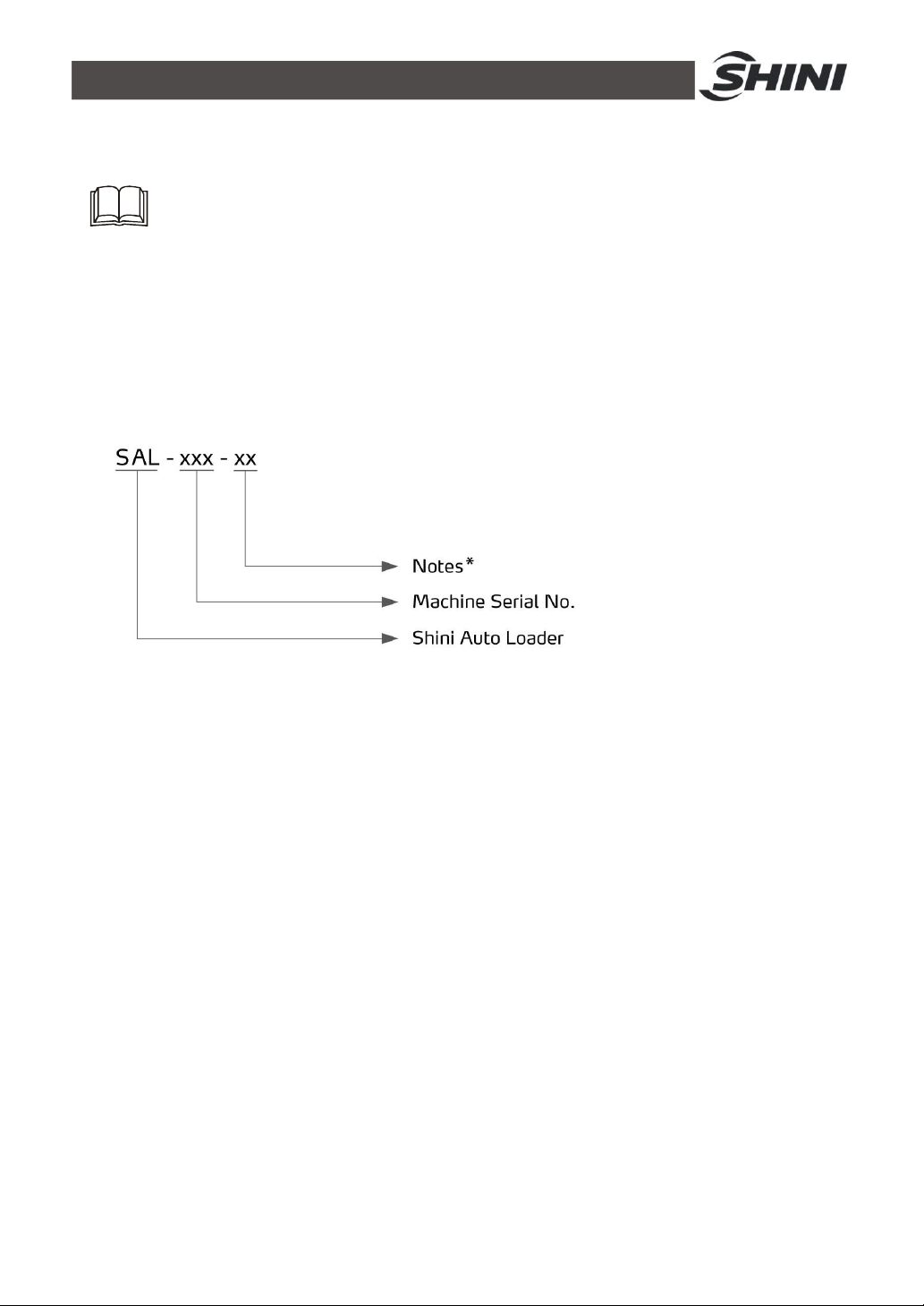
1.1 Coding Principle
Note:*
P=For Polished Hopper Inside CE=CE Conformity
1.2 Main Features:
1) Standard Configuration
l Stainless steel hopper, motor overload protective device.
l All the machines are equipped with hinged hopper lid.
l SAL-330/360 has standard auto reverse cleaning kit and cloth mesh filter.
2) Accessory Option
l For temporary storage of material, SCH-6L storage hopper is available for
SAL-330/360.
l SPV-U is an optional selection for SAL-330/360. (Including control cabinet).
l Buzzer is an optional selection.
l Manual control switch is optional.
7(40)
Page 8

All service work should be carried out by a person with technical training or
corresponding professional experience. The manual contains instructions for
both handling and servicing. Chapter 12, which contains service instructions
intended for service engineers. Other chapters contain instructions for the daily
operator.
Any modifications of the machine must be approved by SHINI in order to avoid
personal injury and damage to machine. We shall not be liable for any damage
caused by unauthorized change of the machine.
Our company provides excellent after-sales service. Should you have any
problem during using the machine, please contact the company or the local
vendor.
Headquarter and Taipei factory:
Tel: (886) 2 2680 9119
Shini Plastics Technologies (Dongguan), Inc:
Tel: (86) 769 8111 6600
Shini Plastics Technologies India Pvt.Ltd.:
Tel: (91) 250 3021 166
8(40)
Page 9
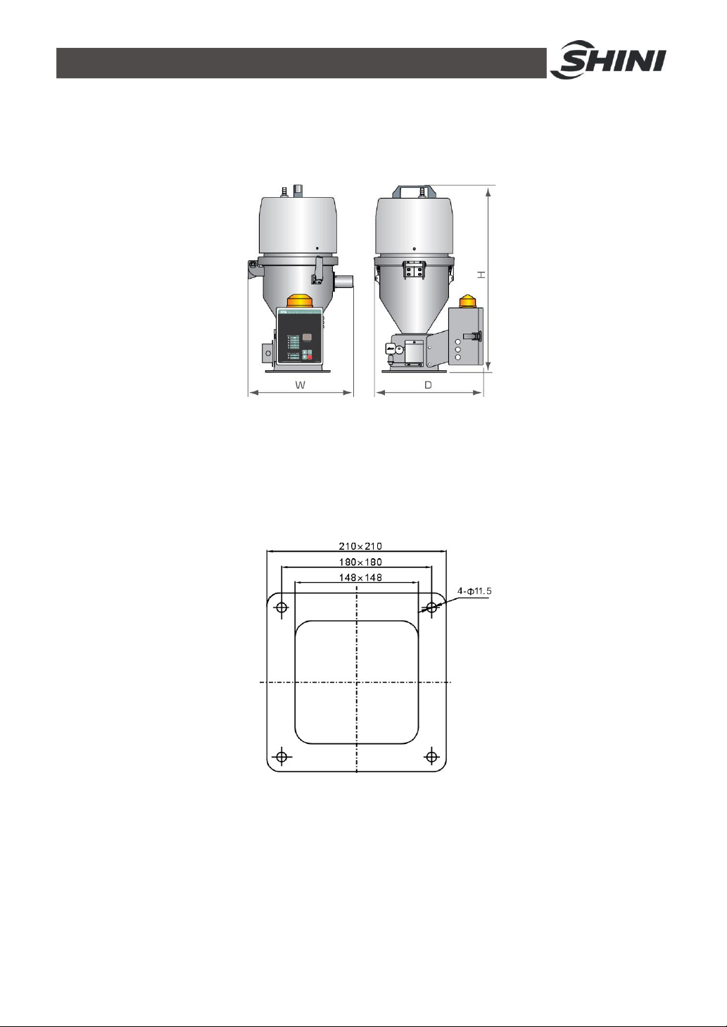
1.3 Technical Specifications
1.3.1 External Dimensions
SAL-330/360
Picture 1-1:External dimensions
1.3.2 Mounting Base Specifications
SAL-330/360
Picture 1-2:Mounting base specifications
9(40)
Page 10
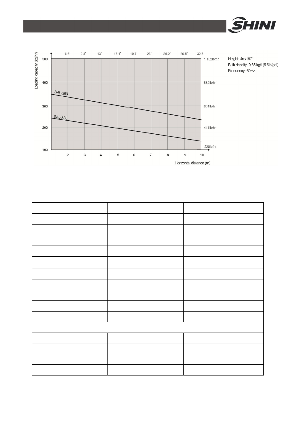
1.3.3 Loading Capacity
Picture 1-3:Loading capacity
1.3.4 Specification List
Table 1-1: Specification list
Model SAL-330 SAL-360
Ver. B B
Motor Type Carbon brush Carbon brush
MotorPower(kW)(50 / 60Hz) 1.15 1.15
Conveying Pipe Dia.(Inch) 1.5 1.5
Conveying Capacity
(kg / hr, 50Hz)
Hopper Capacity (L) 3 6
Input Voltage 1Φ,230V,50Hz
Material Level Control Microswitch Microswitch
Cloth Filter Standard Standard
Auto-cleaning Standard Standard
Dimensions
H(mm) 610 670
W(mm) 345 385
D(mm) 355 380
Weight (kg) 13 14
Note:1) For hopper inside polished ones, add "P" at model behind.
2) Test condition of conveying capacity: Plastic material of bulk density 0.65kg/L, dia. 3~5 mm,
vertical conveying height: 4m, horizontal conveying distance: 1m.V.
200 300
10(40)
Page 11
1.4 Safety Regulations
Please abide by the safety guide when you operate the machine so as to
prevent damage of the machine and personal injuries.
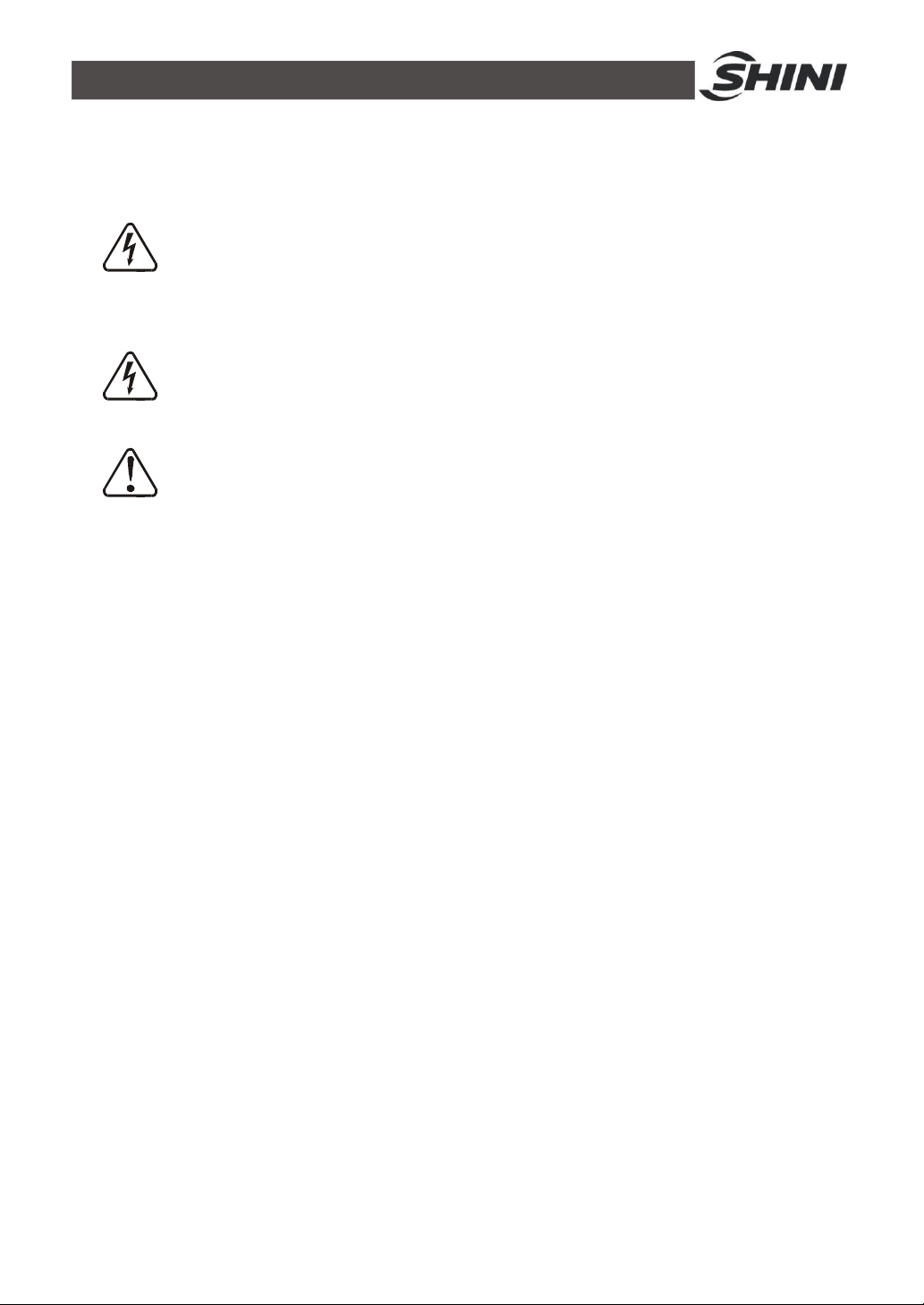
Attention!
All electrical components should be installed by qualified electricians.
Turn off main switch and control switch during repair and maintenance.
Warning! High voltage!
This mark is attached on the cover of the control box.
Warning! Be careful!
Be more careful when this mark appears.
Transportation and Storage of the Machine
Transportation
1) SAL series hopper loader are packed in paper cartons. Handle with care
when to move the machine by hands.
3) Do not rotate the machine and avoid collision with other objects during
transportation to prevent improper functioning.
4) The structure of the machine is well-balanced, although it should also be
handled with care when lifting the machine for fear of falling down.
5) The machine and its attached parts can be kept at a temperature from -25℃
to +55℃ for long distance transportation and for a short distance, it can be
transported with temperature under +70℃.
Storage
1) SAL series hopper loader should be stored indoors with temperature kept
from 5℃ to 40℃ and humidity below 80%.
2) Disconnect all power supply and turn off main switch and control switch.
3) Keep the whole machine, especially the electrical components away from
water to avoid potential troubles caused by the water.
4) Plastic film should be used to protect the machine from dust and rains.
Working Environment
11(40)
Page 12
The machine should be operated:
1) Indoors in a dry environment with max. temperature +45℃ and humidity
nomore than 80%.
Do not use the machine:
1) If it is with a damaged cord.
2) On a wet floor or when it is exposed to rain to avoid electrical shock.
3) If it has been dropped or damaged until it is checked or fixed by a qualified
serviceman.
4) This equipment works normally in the environment with altitude within 3000m.
5) At least a clearance of 1m surrounding the equipment is required during operation.
Keep this equipment away from flammable sources at least two meters.
6) Avoid vibration, magnetic disturbance at the operation area.
Rejected Parts Disposal
When the equipment has run out its life time and can not be used any more,
unplug the power supply and dispose of it properly according to local code.
Fire Hazard!
In case of fire, CO
dry powder fire extinguisher should be applied.
2
1.5 Exemption Clause
The following statements clarify the responsibilities and regulations born by any
buyer or user who purchases products and accessories from Shini (including
employees and agents).
Shini is exempted from liability for any costs, fees, claims and losses caused by
reasons below:
1. Any careless or man-made installations, operation and maintenances upon
machines without referring to the manual prior to machine using.
2. Any incidents beyond human reasonable controls, which include man-made
vicious or deliberate damages or abnormal power, and machine faults caused
by irresistible natural disasters including fire, flood, storm and earthquake.
3. Any operational actions that are not authorized by Shini upon machine, including
adding or replacing accessories, dismantling, delivering or repairing.
4. Employing consumables or oil media that are not appointed by Shini.
12(40)
Page 13
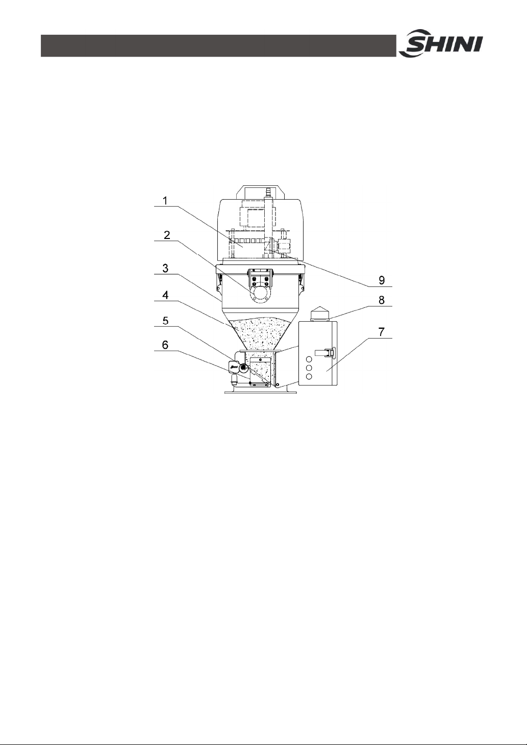
2. Structure Characteristics and Working Principle
Discharging plate
2.1 Working Principle
SAL-330/360 series are suitable for conveying plastic granules. The blower
makes vacuum of material hopper by drawing the air out. Materials will then be
sent into material hopper.
Picture 2-1:Working principle of SAL-330/360
1. Carbon brush blower 2. Material inlet pipe 3. Storage hopper
4. Material 5.
6. Microswitch
7. Control box 8. Alarm light 9.Reverse cleaning device
After starting the machine, reverse cleaning device (9) begins to wash the dust
covered in the hop- pocket and hopper. After that, carbon brush blower (1)
starts to work and produces vacuum in the storage hopper (3). Meanwhile, close
the discharging plate (5), and the material in the storage bucket will be
conveyed through material inlet pipe (2) into the material storage hopper (3)
under the function of minus pressure and the air flow. After finishing material
suction, carbon brush blower(1) stops working and the materials(4) will fall down
by self-gravity. When microswitch (6) detects that no materials remain in the
storage hopper(3), and after the dust get through the reverse cleaning device(9),
the carbon brush blower(1) starts to work again. When blower cannot suck
13(40)
Page 14

materials from the storage bucket, the alarm light (8) in the control box (7) will
be blinking to indicate that the materials are not enough.
14(40)
Page 15
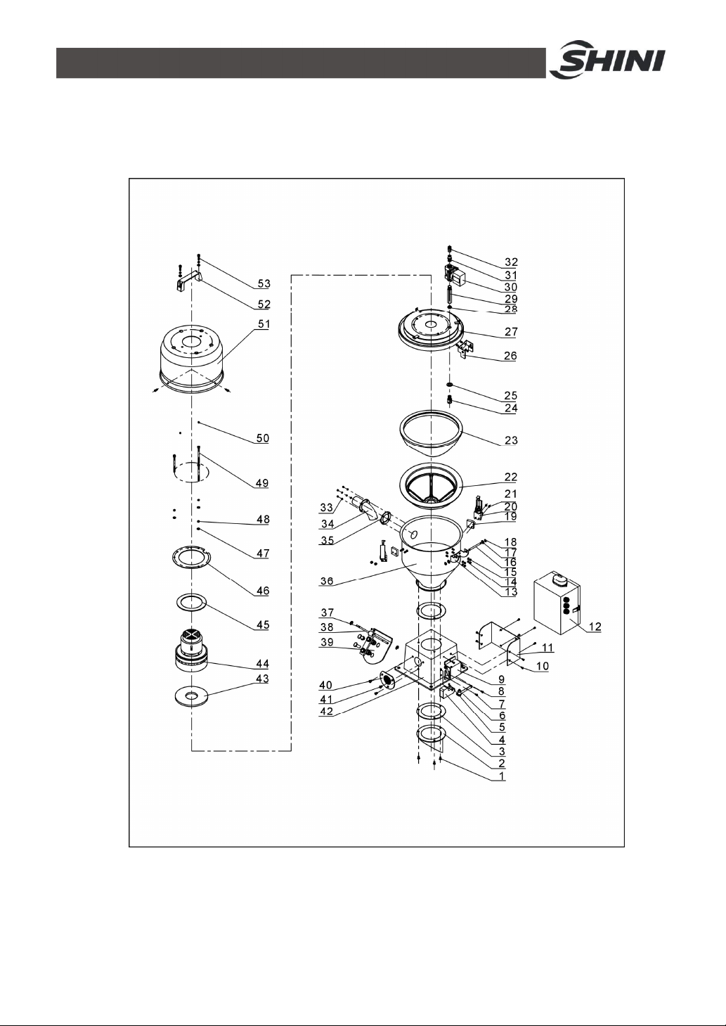
3. Assembly Drawing
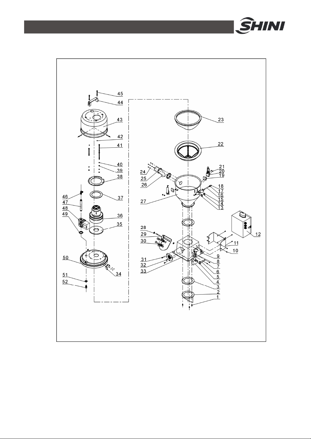
3.1 Assembly Drawing (SAL-330)
Remarks: Please refer to material list 11.2 for specific explanation of the Arabic numbers
in parts drawing.
Picture 3-1:Assembly drawing (SAL-330)
15(40)
Page 16
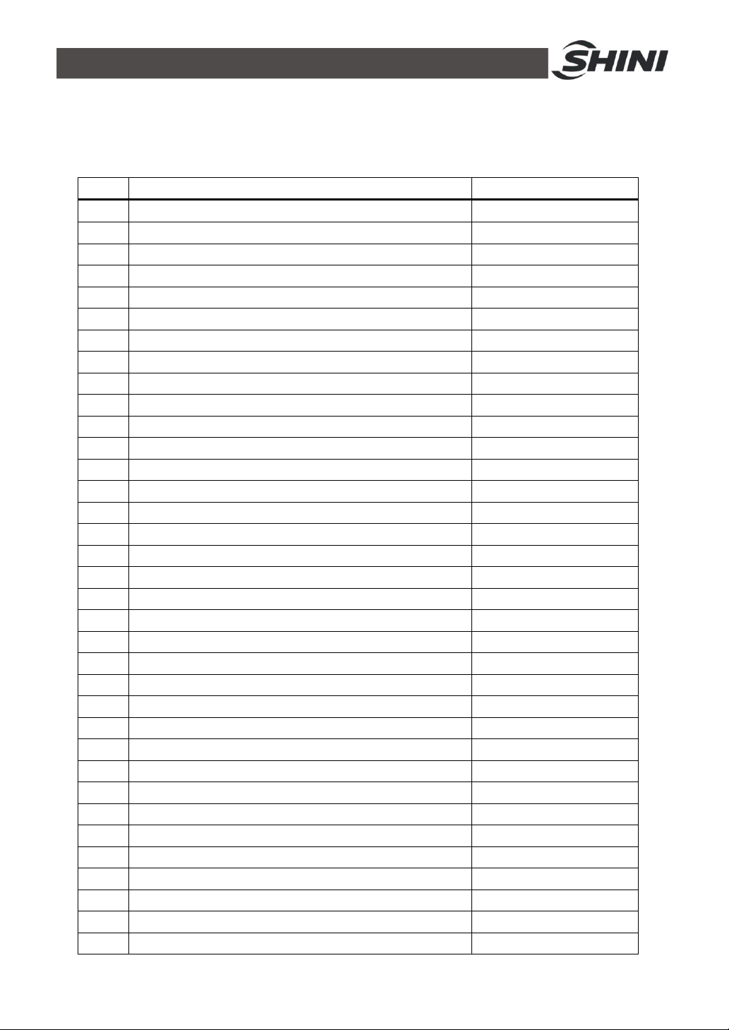
3.2 Parts List(SAL-330)
Table 3-1: Parts list(SL-330)
NO. Past Name Part NO.
1 Cross socket head cap screw M5×20 YW62041200000
2 Discharging port BL20333600020
3 Base fastener YR10000000600
4 Counter weight hammer YW20602100000
5 Set screw M5×5 YW68005500000
6 Ejector pin assembly BH10000600050
7 Cross socket head cap screw M4×10 YW63041000000
8 Microswitch YE14511200000
9 Microswitch box YR40330900000
10 Cross socket head cap screw M5×10 YW62051000100
11 Control box fixing plate BL20333600120
12 Control box BH32336000350
13 Lower hinge BL32000600140
14 Flat washer 5 YW66051000100
15 Locknut M5 YW64000500000
16 Hinge pin BH10006003110
17 Flat washer 8 YW66082200100
18 E-rings 6 YW66000600000
19 Snap hook block YR40000600300
20 Snap hook YW02003000400
21 Locknut M4×0.7 YW64040700100
22 Split washer of filter cloth ** YR40003000100
23 Filter bag** BP82003000044
24 Reverse cleaning pipe nozzle BH13033000810
25 Washer BP62201000050
26 Upper hinge BL32000600240
27 Hopper cover BL21033000160
28 Connection nut BH12030400410
29 Connector 2 BH13030300010
30 Solenoid valve YE32213100000
31 Connector 3 BH13031100010
32 Thread direct connector YW80081400000
33 Flat washer 4 YW66040800000
34 Material inlet pipe BL32333600020
35 Material inlet pipe fastener YR10150300000
16(40)
Page 17
36 Storage hopper -
37 E-rings 5 YW66000300000
38 Iron rod BH11061400010
39 Material discharging plate assembly BH90601200050
40 Air vent window YR40002400000
41 Cross socket head cap screw M6×10 YW62061000000
42 Square base BA10040000210
43 Motor fastener(lower) ** YR10135500000
44 Carbon brush blower** YM30965600000
45 Motor fastener(upper) ** YP62141200000
46 Motor fixing plate BL21000300420
47 Flat washer 6 YW66061300000
48 Spring washer 6 YW65006000000
49 Inner hexagon column screw M6×90 YW61069000100
50 Locknut M6 YW64000600200
51 Cover YR40033000000
52 L120 aluminum square handle BW20012000040
53 Inner hexagon column screw M6×20 YW61062000200
* means possible broken parts. ** means easy broken part. and spare backup is suggested.
Please confirm the version of manual before placing the purchase order to guarantee that the item number
of the spare part is in accordance with the real object.
17(40)
Page 18
3.3 Assembly Drawing (SAL-360)
Remarks: Please refer to material list 11.4 for specific explanation of the Arabic numbers
in parts drawing.
Picture 3-2:Assembly drawing (SAL-360)
18(40)
Page 19
3.4 Parts List(SAL-360)
Table 3-2: Parts list(SL-360)
NO. Past Name Part NO.
1 Cross socket head cap screw M5×20 YW62041200000
2 Discharging port BL20333600020
3 Base fastener YR10000000600
4 Counter weight hammer YW20602100000
5 Set screw M5×5 YW68005500000
6 Ejector pin assembly BH10000600050
7 Cross socket head cap screw M4×10 YW63041000000
8 Microswitch YE14511200000
9 Microswitch box YR40330900000
10 Cross socket head cap screw M5×10 YW62051000100
11 Control box fixing plate BL20333600120
12 Control box BH32336000350
13 Lower hinge BL32000600140
14 Flat washer 5 YW66051000100
15 Locknut M5 YW64000500000
16 Hinge pin BH10006003110
17 Flat washer 8 YW66082200100
18 E-rings 6 YW66000600000
19 Snap hook block YR40000600300
20 Snap hook** YW02003000400
21 Locknut M4×0.7 YW64040700100
22 Filter bag** YR40006000000
23 Filter cloth ** BP82006000044
24 Flat washer 4 YW66040800000
25 Material inlet pipe BL32000600020
26 Material inlet pipe fastener YR10000600300
27 Storage hopper -
28 E-rings 5 YW66000300000
29 Iron rod BH11061400010
30 Material discharging plate assembly SAL BH90601200050
31 Air vent window YR40002400000
32 Cross socket head cap screw M6×10 YW62061000000
33 Square base BA10040000210
34 Upper hinge BL32000600240
35 Motor fastener (lower) ** YR10135500000
19(40)
Page 20
36 Carbon brush motor ** YM30965600000
37 Motor fastener(upper) ** YP62141200000
38 Motor fixing plate BL21000300420
39 Flat washer 6 YW66061300000
40 Spring washer 6 YW65006000000
41 Inner hexagon column screw M6×90 YW61069000100
42 Locknut M6 YW64000600200
43 Cover BR40036000010
44 L120 aluminum square handle BW20012000040
45 Inner hexagon column screw M6×20 YW61062000200
46 L-type thread connector YW80081400100
47 Connector 2 BH13030300010
48 Solenoid valve YE32213100000
49 Connection nut BH12030400410
50 Hopper cover -
51 Washer BP62201000050
52 Reverse cleaning pipe nozzle BH13033000810
* means possible broken parts. ** means easy broken part. and spare backup is suggested.
Please confirm the version of manual before placing the purchase order to guarantee that the item number
of the spare part is in accordance with the real object.
20(40)
Page 21
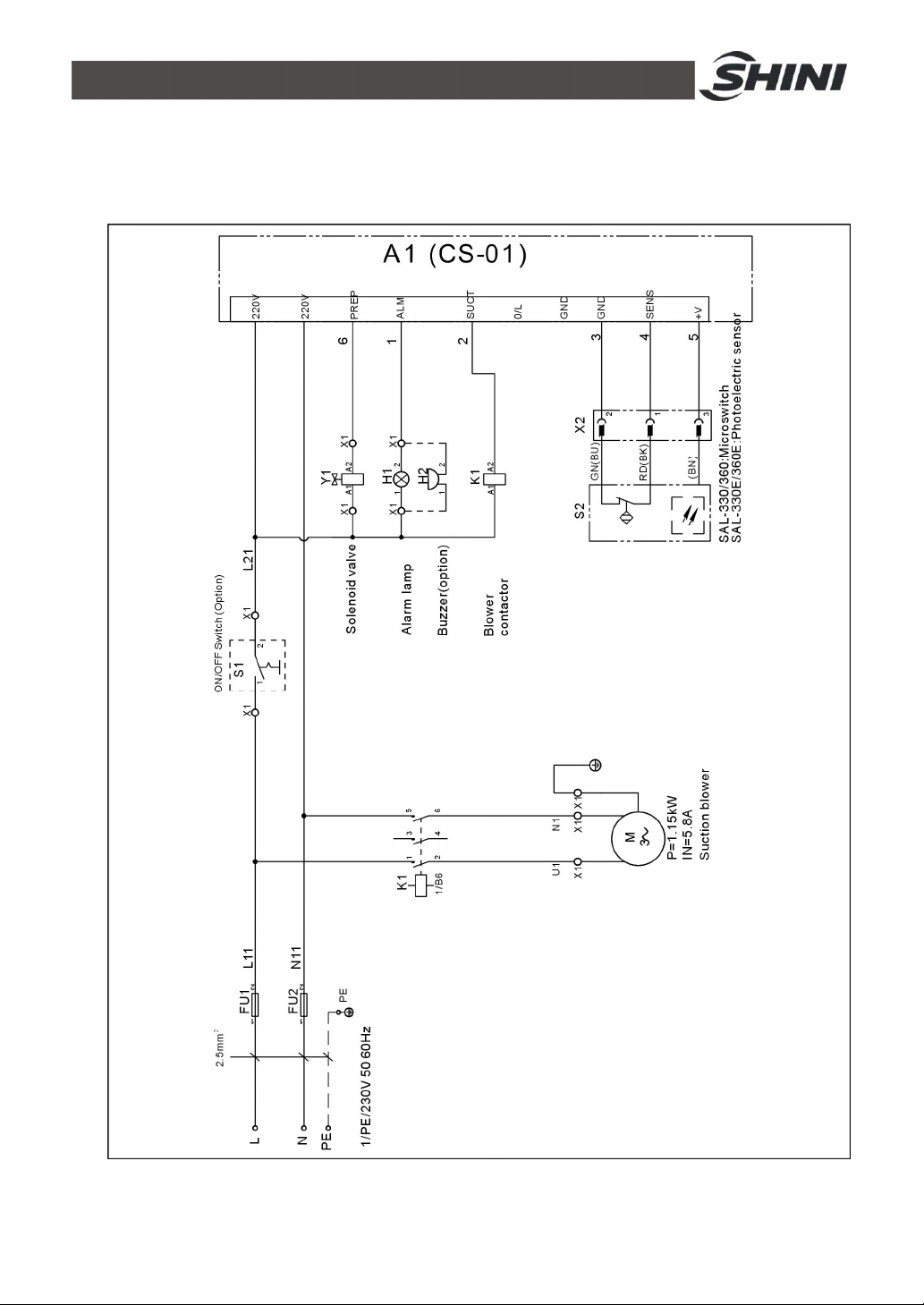
4. Electrical Circuit Diagram
4.1 Electrical Diagram
Picture 4-1:Electrical diagram
21(40)
Page 22
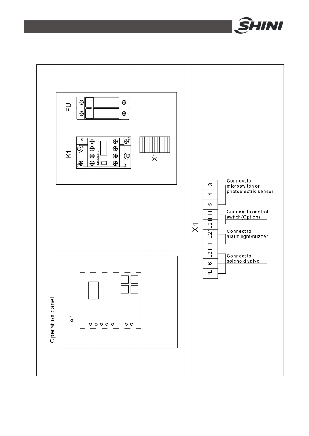
4.2 Electrical Components Layout and Terminal Connection
Diagram
Picture 4-2:Electrical components layout and terminal connection diagram
22(40)
Page 23
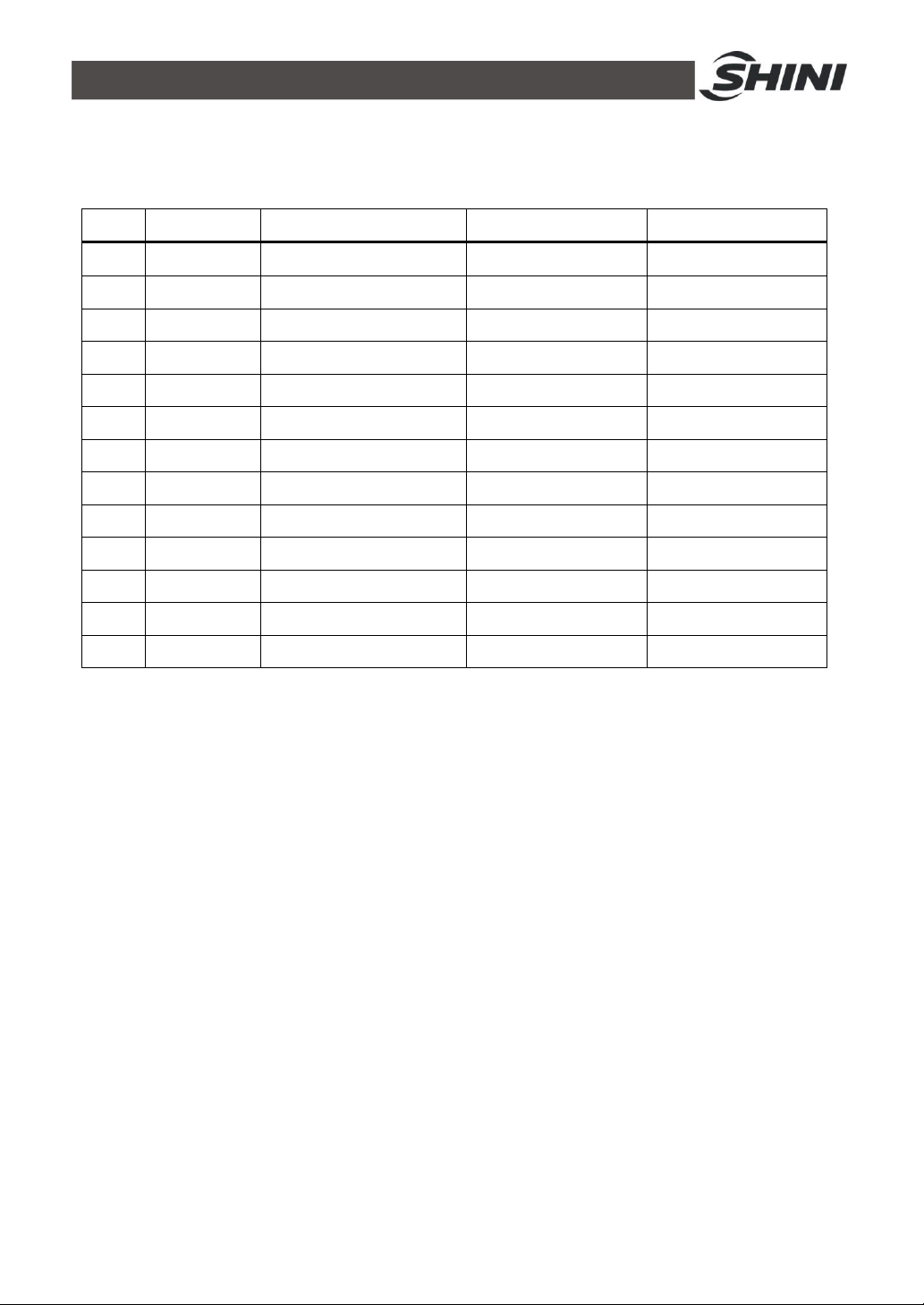
4.3 Electrical Components List
Table 4-1: Electrical components list
NO. Symbol Parts Name Specification Part No.
1 FU1 U2 Fuse base 1P YE41142000000
2 - Fuse** 10A YE46010000100
3 K1 Contactors** 220VAC 50/60Hz YE00601621000
4 H1 Alarm light 220VAC 50/60Hz YE83305100200
5 H2 Buzzer 220VAC 50/60Hz YE84003500000
6 A1 Circuit board** 220VAC 50/60Hz YE80122000000
7 S1 Control switch 250V 10A YE10030300000
8 S2 Microswith* 400V 10A YE14511200000
9 - Photoelectric sensor 10-30VDC YE15143900000
10 X1 Terminal board 2.5mm² YE61250040000
11 - - 2.5mm² YE61250040000
12 - - 2.5mm² PE YE61253500000
13 M Blower 1.15KW -
* means possible broken parts. ** means easy broken part. and spare backup is suggested.
Please confirm the version of manual before placing the purchase order to guarantee that the item number of
the spare part is in accordance with the real object.
23(40)
Page 24
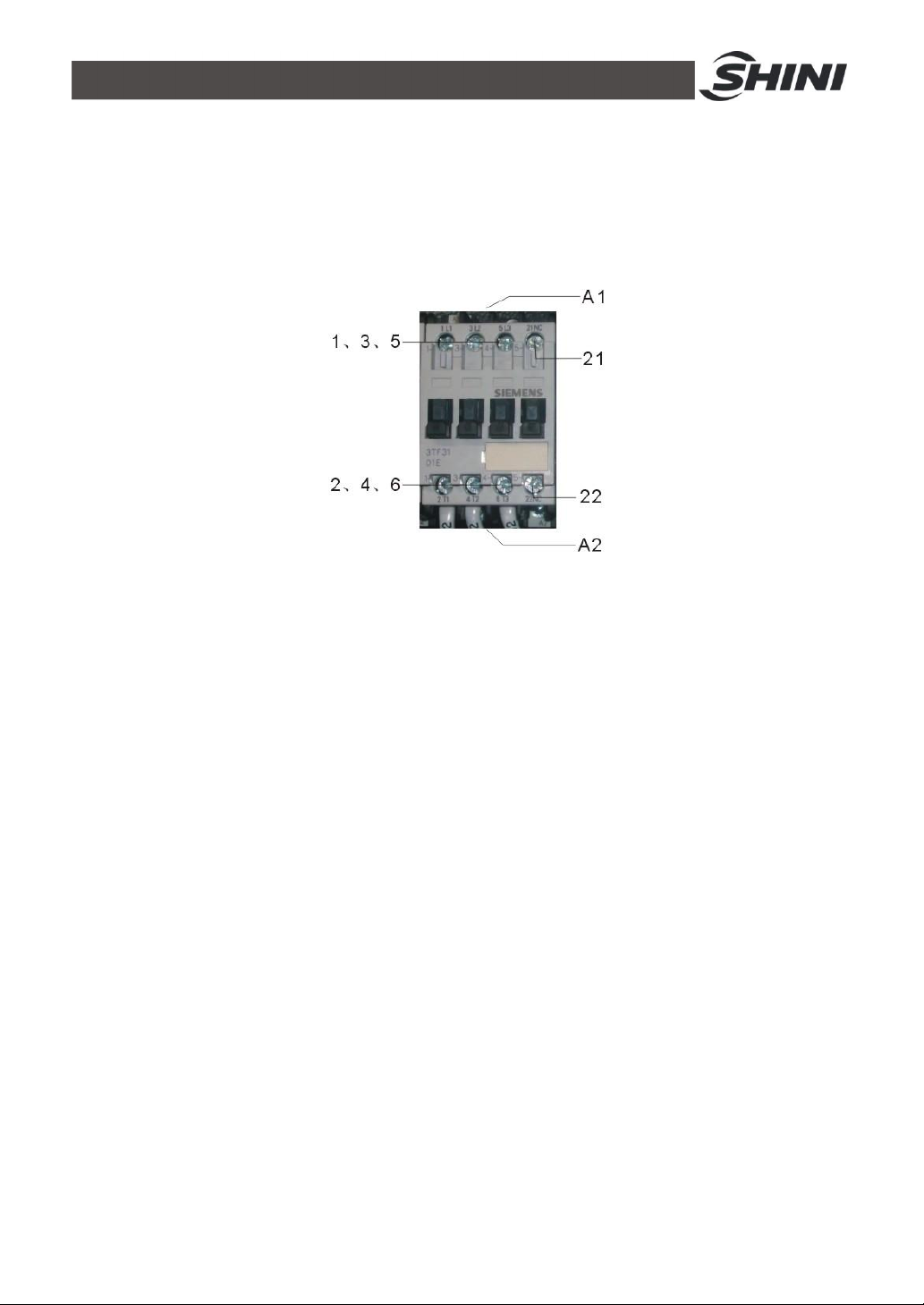
4.4 Main Electrical Components Description
4.4.1 AC Contactor
It is mainly used to connect and disconnect power supply
Picture 4-3:Contactor
A1-A2: Contactor coil 21-22: Contact 21-2. 3-4. 5-6: Main contact
24(40)
Page 25
5. Installation and Debugging
s no
Make a careful study of this chapter before installation.
The machine must be installed according to the steps below. Power
supply should be connected by qualified electricians.
5.1 Installation of SAL-330 / 360
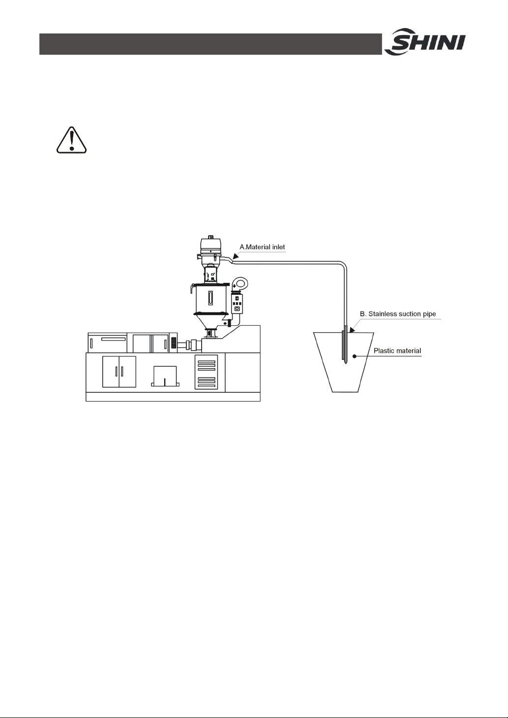
5.1.1 Installation Methods of SAL-330 / 360
Picture 5-1:Installation methods of SAL-330/360
Notes for Installation and Positioning:
1) Machine just can be mounted in vertical position. Make sure there’
pipe, fixed structure or other objects above the installing location and around
the machine which may block machine’s installation, hit objects or injure
human person.
2) For easy maintenance, it’s suggested to leave 1m space around the machine.
3) Machine should be placed on water-level surface. If it needs to be mounted
on a higher surface (e.g. the scaffold or the interlayer), should ensure its
structure and size could bear the weight and size of the machine.
Machine Installation
Install the whole suction machine (SAL-330 / 360) onto the hopper dryer (see
the picture above), fix the four fixation holes in the mounting base. Connect one
25(40)
Page 26
end of the conveying hose to material inlet (A), and the other end to the
stainless suction pipe (B), then insert the pipe into the storage tank.
Circuit Connection
The machine requires compressed air to finish filter cleaning function, so please
connect to the compressed air. The pressure of compressed air: 4~6kgf/cm2
Please make sure that the main power is shut off when you connect the
machine with power supply!
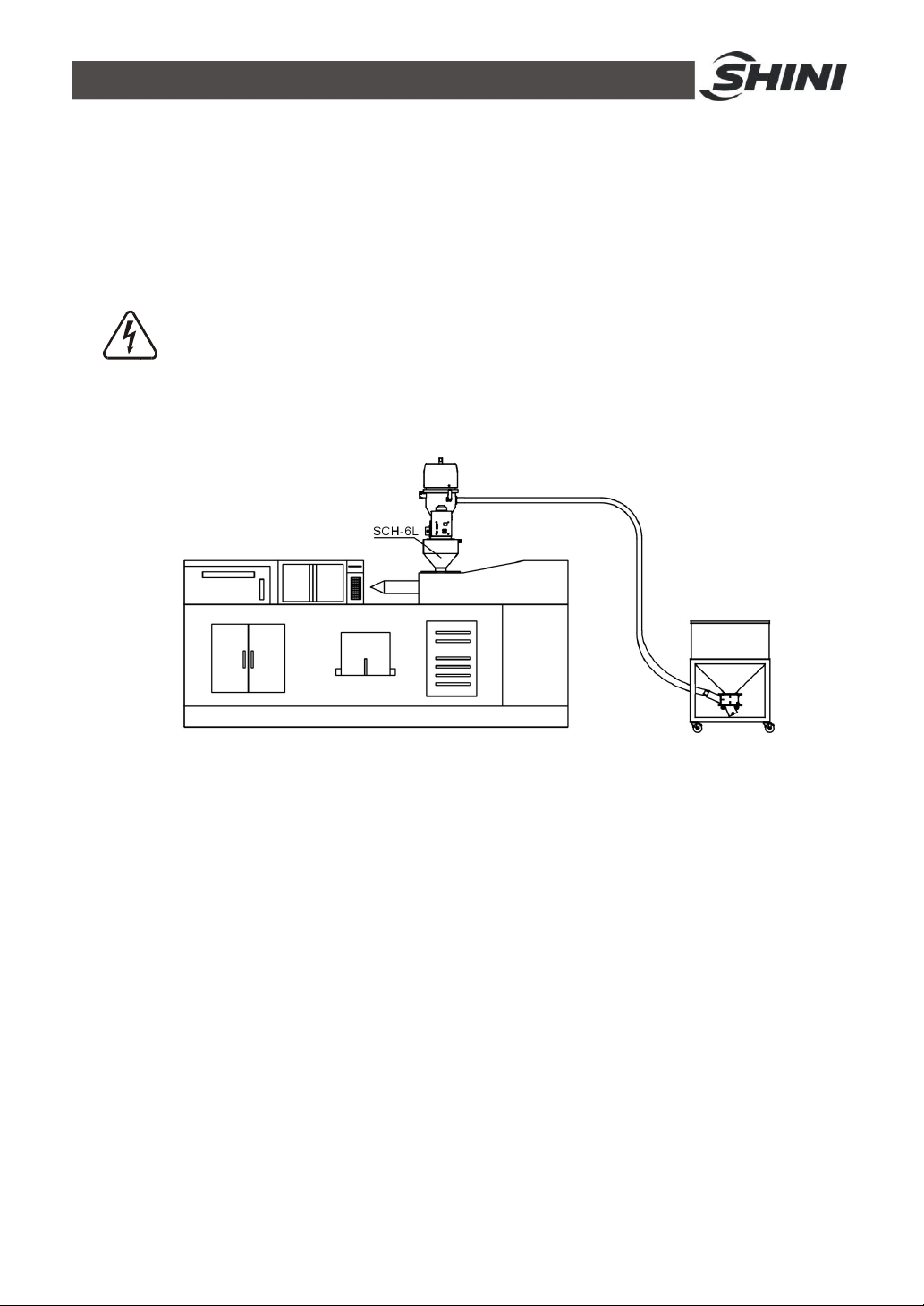
5.1.2 Installation Methods of SAL-330/360 Optional Collective Hopper SCH-6L
Picture 5-2:Installation method of optional SCH-6L
Machine Installation
Mount SCH-6L at the material inlet of molding machine, point it to the mounting
holes and lock up with screws. Mount hopper loader onto the SCH-6L, point it to
the mounting holes and lock up the screws. Connect one end of material pipe to
suction inlet of the hopper loader, insert the other end in the hopper.
Circuit Connection
The machine requires compressed air to finish filter cleaning function, so please
connect to the compressed air. The pressure of compressed air: 4~6kgf/cm2
26(40)
Page 27
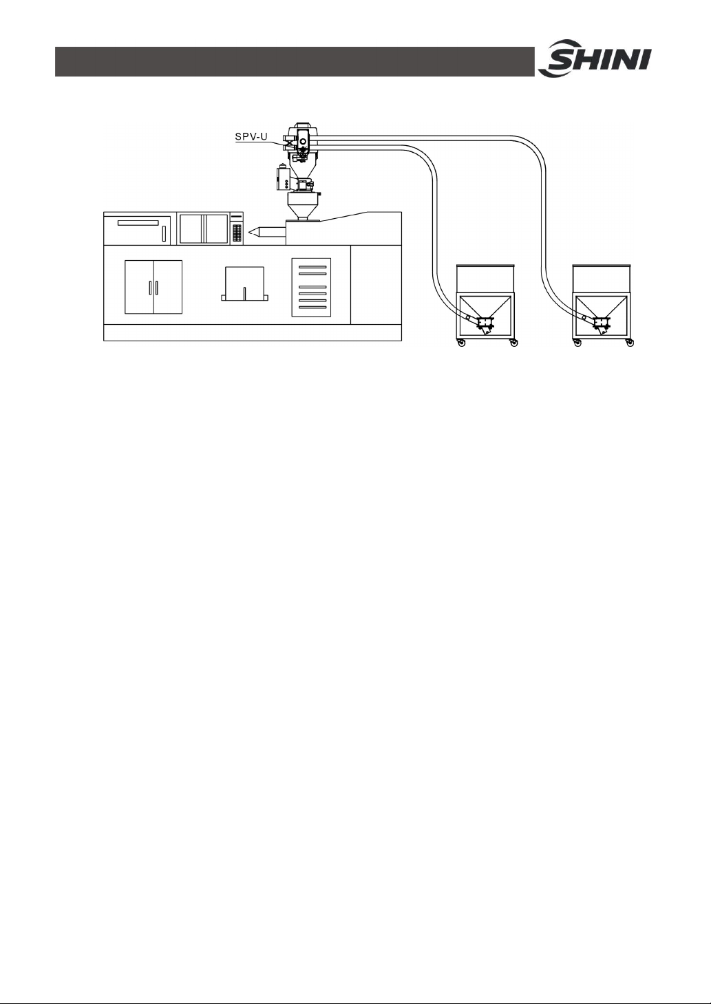
5.1.3 Installation Methods of SAL-330/360 Optional Proportional Valve SPV-U
Picture 5-3:Installation method of optional SPV-U
Machine Installation
Mount SPV-U at material inlet of SAL-330/360, connect two material inlets of
SPV-U to two feeding pipes respectively, insert another end of the feeding pipes
in the hoppers.
Circuit Connection
The machine requires compressed air to finish filter cleaning function, so please
connect to the compressed air. The pressure of compressed air: 4~6kgf/cm2
27(40)
Page 28
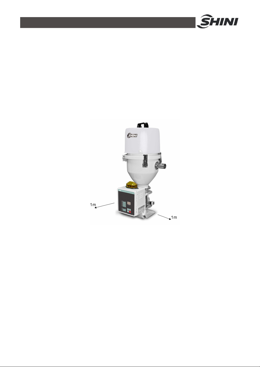
5.2 Installation Space
During installation of the machine, keep at least 1m installation space around
the machine as shown by the picture.
Do not install the machine in a position crowded with other objects. This would
cause inconvenience to operation, maintenance and repair.
Do not sit on the machine.
Keep away flammable and explosive goods.
Picture 5-4:Installation space
28(40)
Page 29
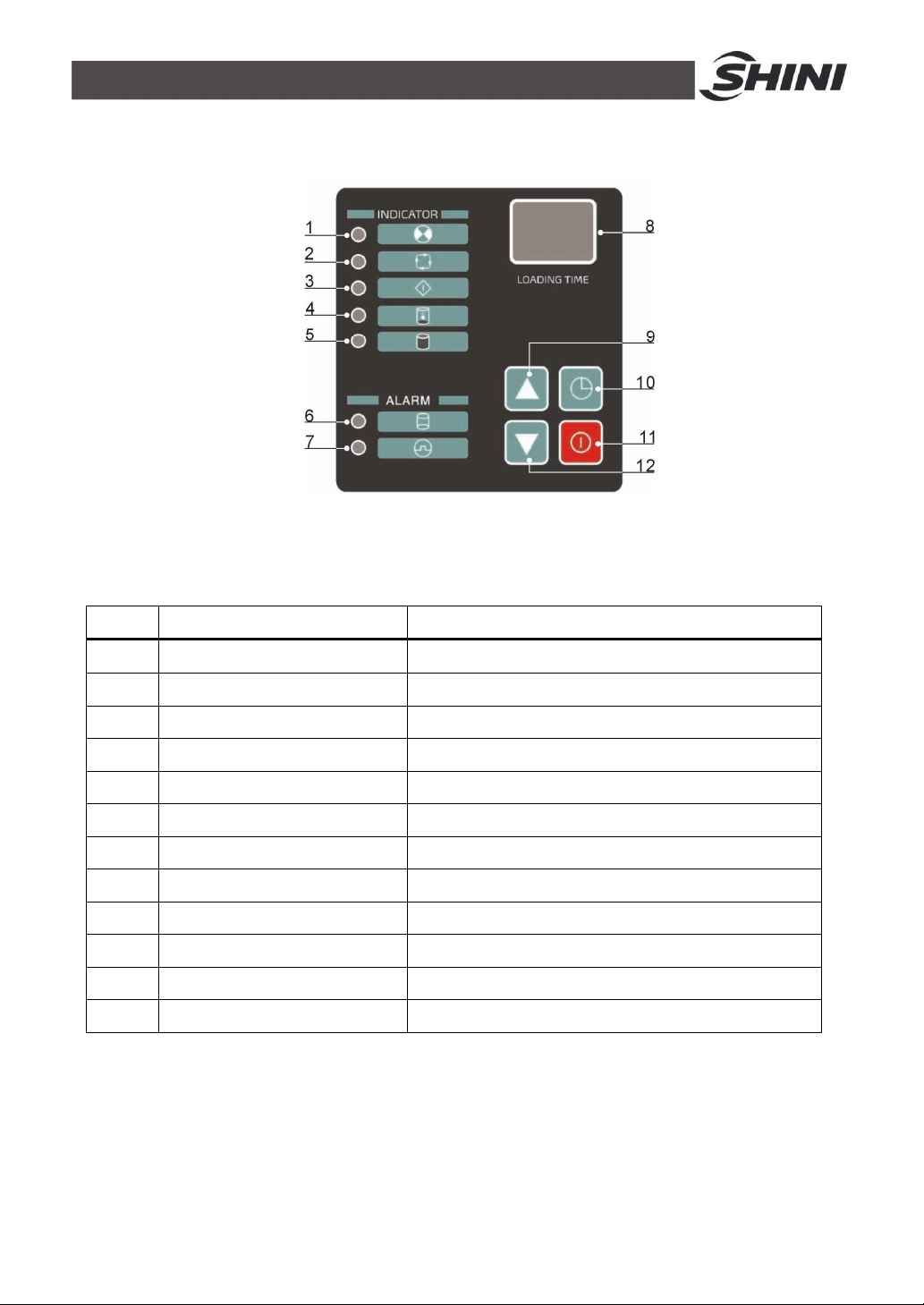
6. Application and Operation
Picture 6-1:Control panel
Table 6-1: Control panel description
No. Description Function
1 Power indicator Machine power on
2 Operation indicator Machine run or stop
3 Preparation indicator Suction preparation
4 Suction indicator Material suction
5 Full load indicator Hopper full load
6 Shortage indicator Material shortage
7 Overload indicator Motor alarm
8 Time/parameter display Display the time/parameter
9 Increase key Add the value
10 Set key Enter parameter setting
11 Start/stop key Machine start/stop control
12 Decrease key Decrease the value
29(40)
Page 30
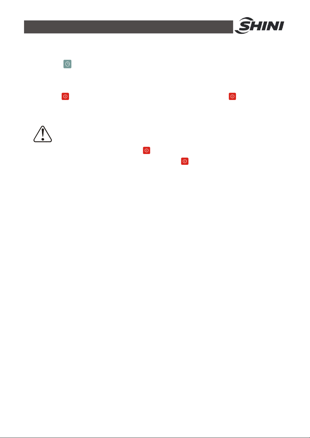
6.1 Control Panel
1. Press to set a proper conveying time of material. For commonly used
materials, set the conveying time as 20 seconds.
2. Press to make the machine start loading material. Press again to
stop working of the machine.
The machine will stop working and sound the alarm at the time of
material shortage. Press to switch off the machine. After adding
material or fixing the problem, press to make the machine resume
working.
Please clean the filter screen periodically to keep effective suction
power.
30(40)
Page 31
6.2 Function Setup
6.2.1 Setup
31(40)
Page 32
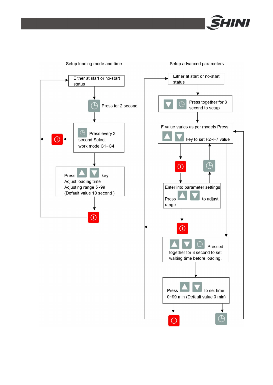
6.2.2 Actions
1. Press down to switch between start / stop status.
2. Press key to select loading mode.
Mode
Auto loading, material shortage alarms whenever no
C1
material being loaded.
C2 After auto loading,purge as per set period and times. Applicable to SAL-330 / 360 models
C3 Motor reverse running for dust separating. Applicable to SAL-430 / 460 models
Auto loading, material shortage alarms after three
C4
time no material being loaded.
Meaning Suitable model
Applicable to SAL-700G / 800G
models
Applicable to SAL-700G / 800G
models
3. At standby state, the seven sectional display will display loading time.
4. Action flow:
32(40)
Page 33
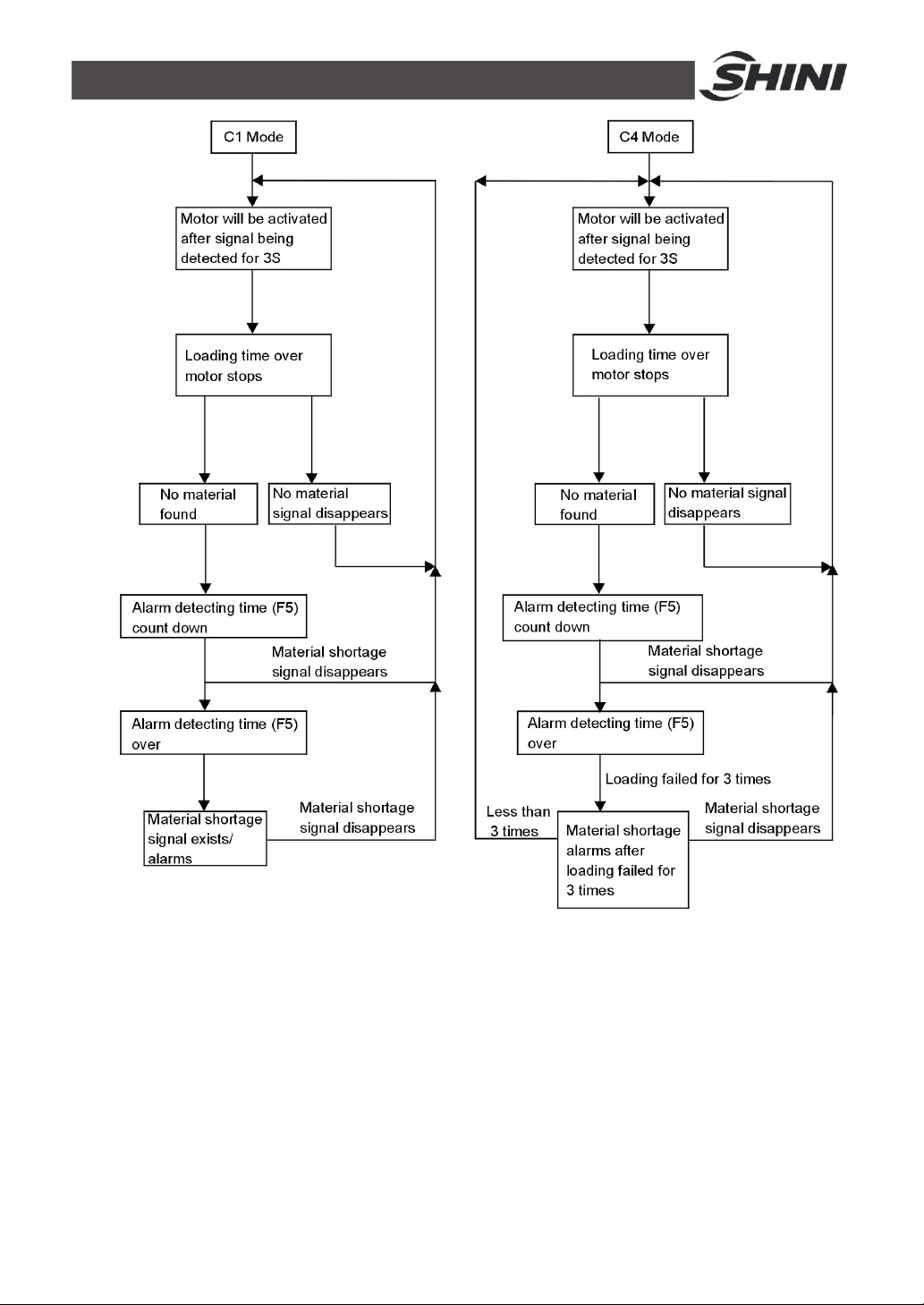
33(40)
Page 34
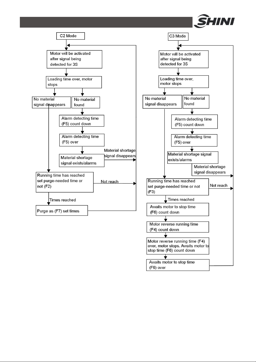
34(40)
Page 35
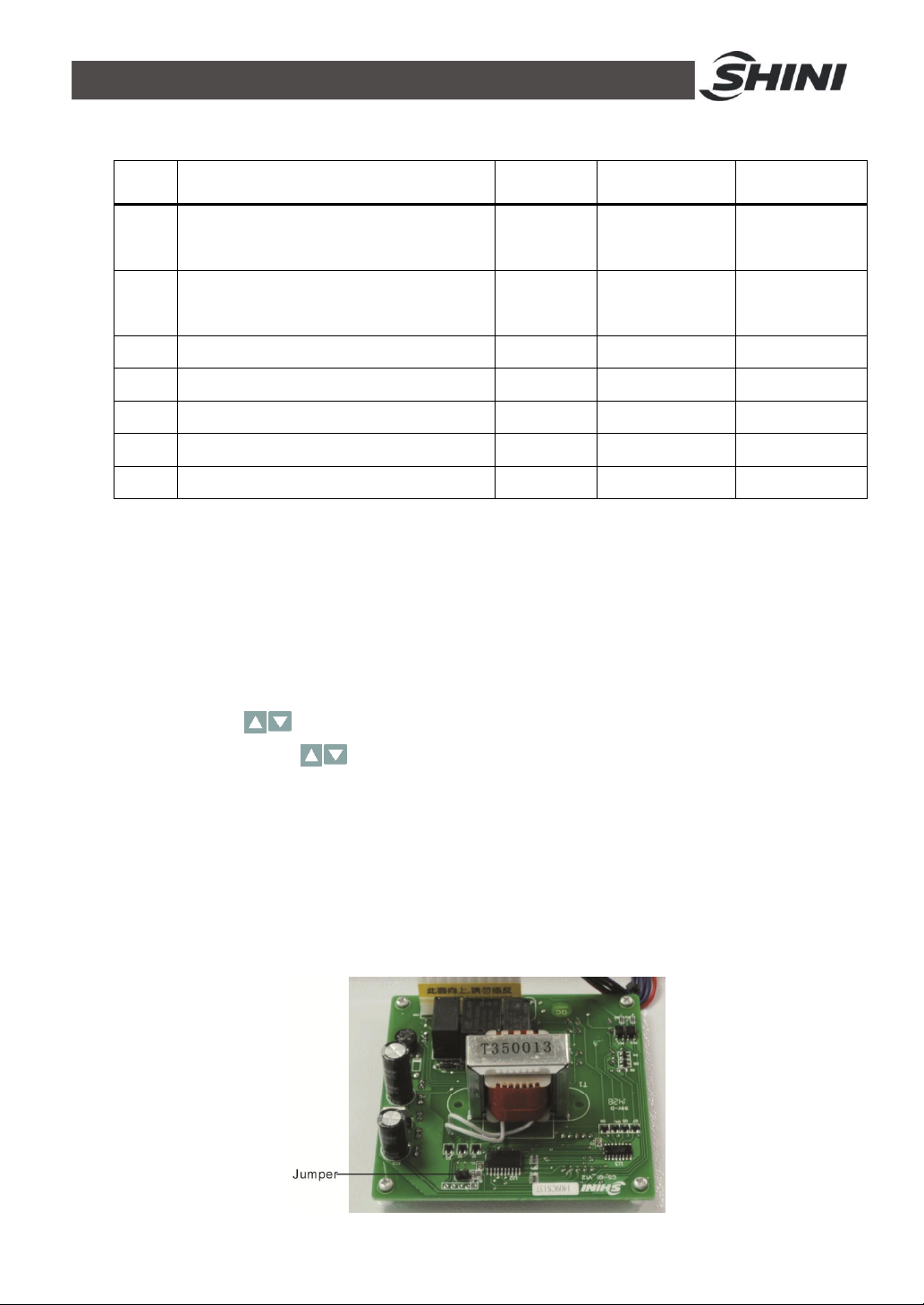
6.2.3 Parameter List
Code
Necessary spray washing times every
F2
several times for operation
Necessary cleaning times for reverse
F3
running every several times of operation
F4 Motor reverse running time 10sec 5~30 sec C3
F5 Alarm detecting time 20 sec 10~40 sec C1,C2,C3,C4
F6 Awaits motor to stop time 30 sec 30~99 sec C3
F7 Purge times 2 times 1~5 times C2
F8 Loading latency time 0 0~99 times C1,C2,C3,C4
Status
Default
Value
3times 1~10 times C2
3 times 1~10 times C3
Adjusting
Range
Mode
6.2.4 Other Settings
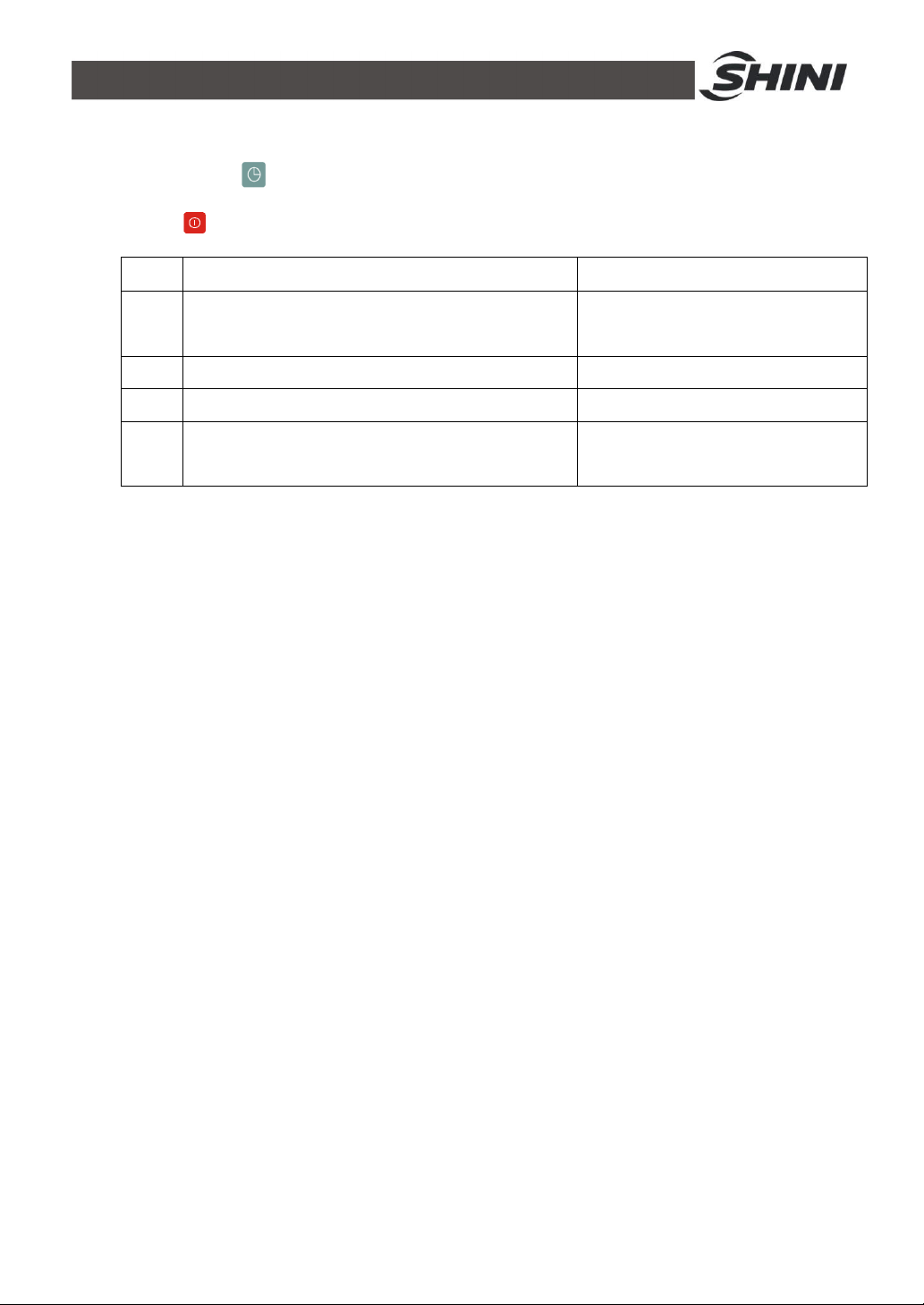
1. Any setting before power on will be saved automatically and back to shut off
state after 5 second of no operation.
2. Any setting after power on will be saved automatically and back to standby
state after 5 second of no operation.
3. No material shortage signal is being detected even after all action is over,
then if press key for 3 second,motor will perform reverse running action,
when release the keys to stop motor and await the motor stop count
down and back to standby state to detect material shortage signal. (The
function only suitable for SAL-430/460 model)
4. Function of the jumper: functions of C1, C3 and C4 will be activated when
jumping out which is applicable to SAL-700G / 800G / 430 / 460. When
disconnected, only functions of C1, C2 and C4 are available which can be
used for SAL-700G / 800G / 330 / 360.
35(40)
Page 36
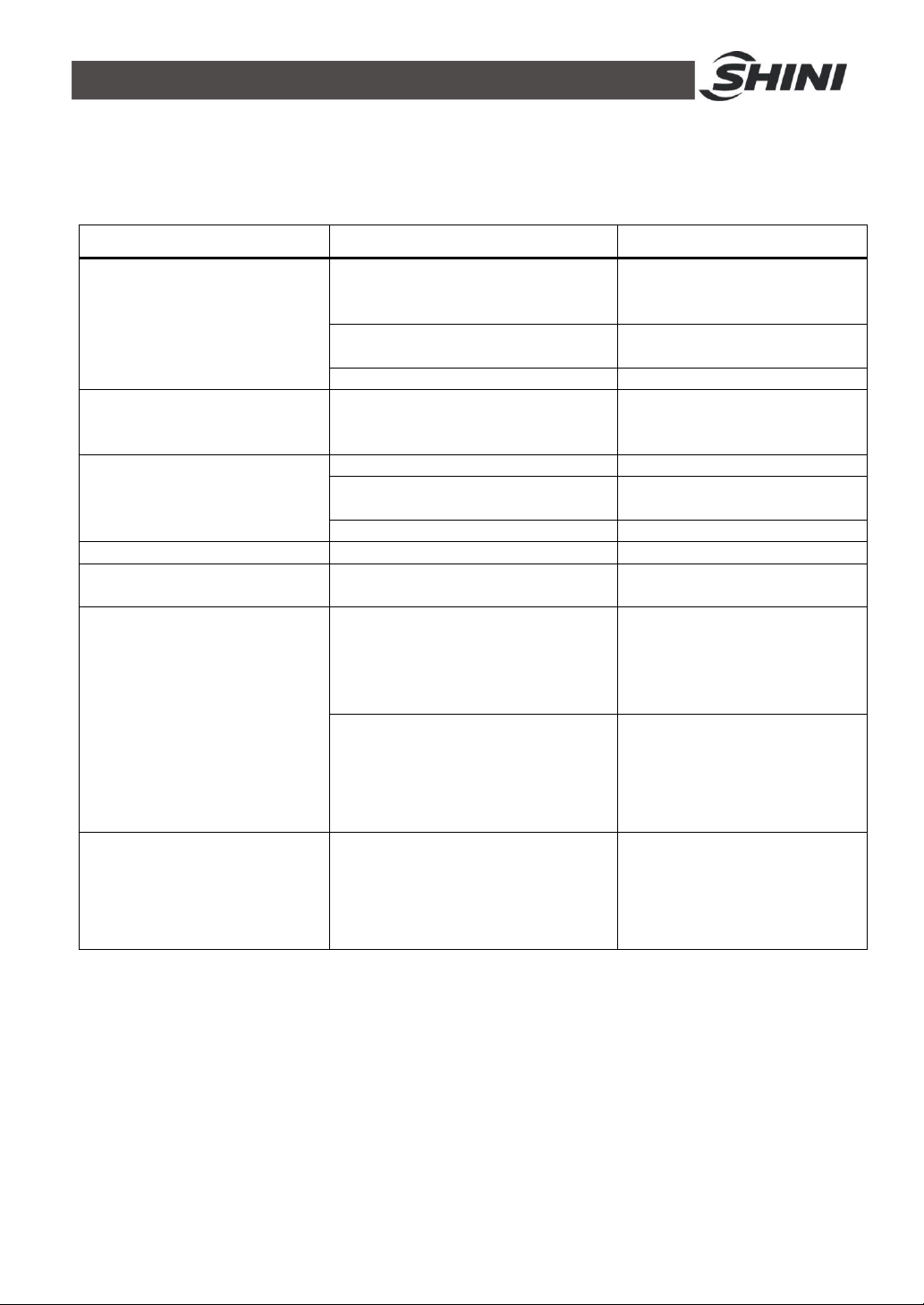
7. Troubleshooting
oor material liquidityin the pipe
7.1 Troubleshooting for SAL-330/360 Series
Failures Possible Causes Solutions
Did not turn on main power or
control switch or poor connection of the
Motor does not work long after
material discharged
Motor keep on working
after the hopper is full
filled
Can not full-load the
material for several times or
alarm indicating
material shortage
Motor does not work Short of phase or motor failures Repair or replace
Fuse melt after startup of the
machine
switches
Poor connection of microswitch or
photoelectrical sensor
Signal wire broken Refix signal wire
Contactor malfunctions Repair or replace contactor
Material is used up Add material to storage bin
Leakage in conveying hose
Filter screen is blocked Clear up filter screen
Short circuit or motor failures Check electrical circuit
Turn on main power switch and
control switch and make sure
they keep good contact.
Adjust or replace
Lock up or replace conveying
hose
The alarm indicating
motor overload
P
Filter screen is blocked
Phase shortage
Over or lack of air quantity
After cleaning of filter
screen,press Reset on the
overload relay.
After fixed the circuit, press Reset on
the overload relay.
Adjust air inlet location of the
suction box.
Avoid small bending of the
elbow.
36(40)
Page 37
8. Maintenance and Repair
All repair work should be done by professionals to prevent personal injuries and
damages of the machine.
8.1 Filter Screen
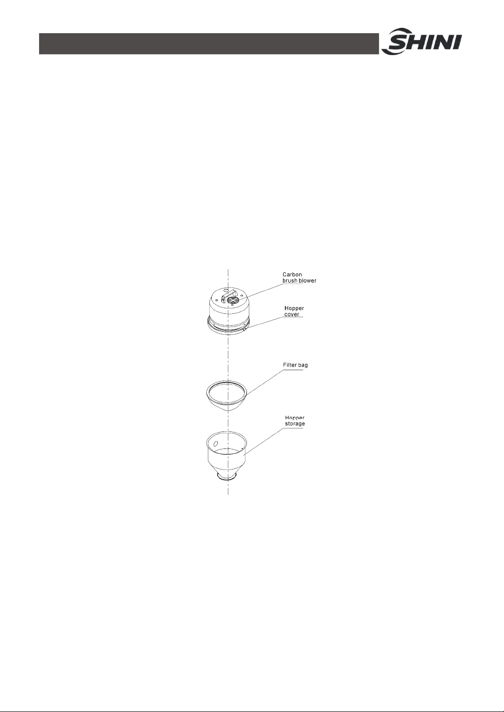
1) For SAL-330/360 series, filter screens are fitted. They need to be cleaned
periodically or at the time when conveying capacity of the machine decreases.
Loosen the clips or screws at the hopper lid, take down the hopper lid and
take the filter screen out. Clear up all the dusts and impurities on the filter
screen to make smooth airflow through the screen so that suction power of
the machine can be enhanced.
Picture 8-1:Filter screen
2) Check the status of motor perfomance. If the motor can not start or makes
loud noises, repair or replace the motor.
37(40)
Page 38
8.1.1 Service Life of Product Key Part
Name of the Parts Service Life
Motor Above 5 years
Contactor Above 100,000 act
8.2 Hopper
1) Loose the snap hook, and take out hopper cover.
2) Use high pressure air to blow away all the material remains.
3) Re-fix the hopper cover and fasten the snap hook.
Note!
please make sure that the main switch is shut off before cleaning.
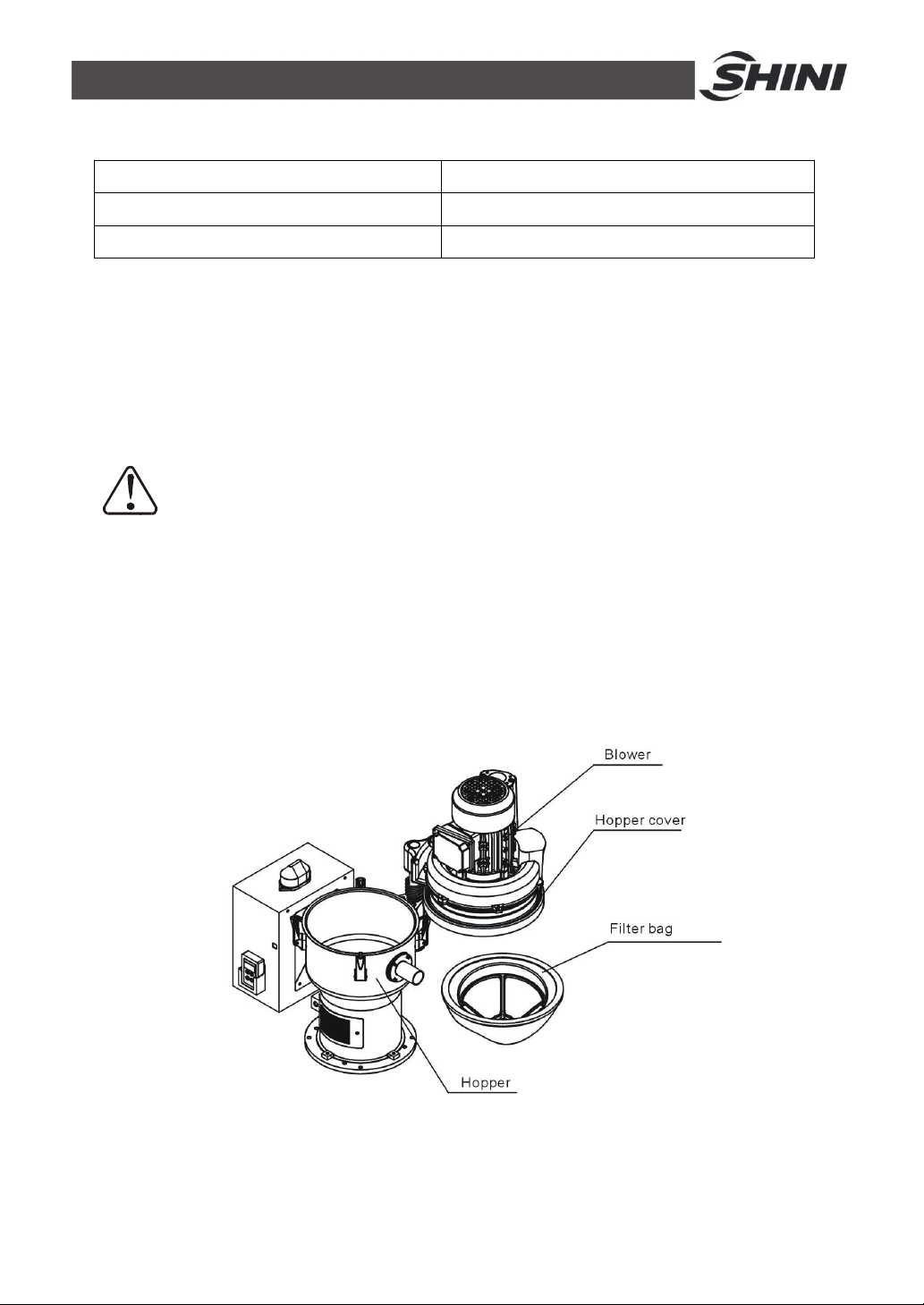
8.3 Cloth Filter
1.Loosen the spring fastener on the loader, uplift the loader cover and externally
rotate it along the axis, take out the filter bag and clear away the dust on it.
2. Filter bag cleaning period: Daily.
Picture 8-2:Cloth filter
38(40)
Page 39

8.4 Blower
1) Clear the blower from inside out regularly. If there are too much dirts
accumulated on the blower, the function of the blower will be affected, such
as temperature rising, reduced air volume, higher noise level and vibration.
All the above factors are liable to cause mechanical problems.
2) The bearing, seal ring and silencer are consumable parts. They should be
replaced after a period of time. The fans, covers, and metal screen also
need to be replaced when necessary.
39(40)
Page 40
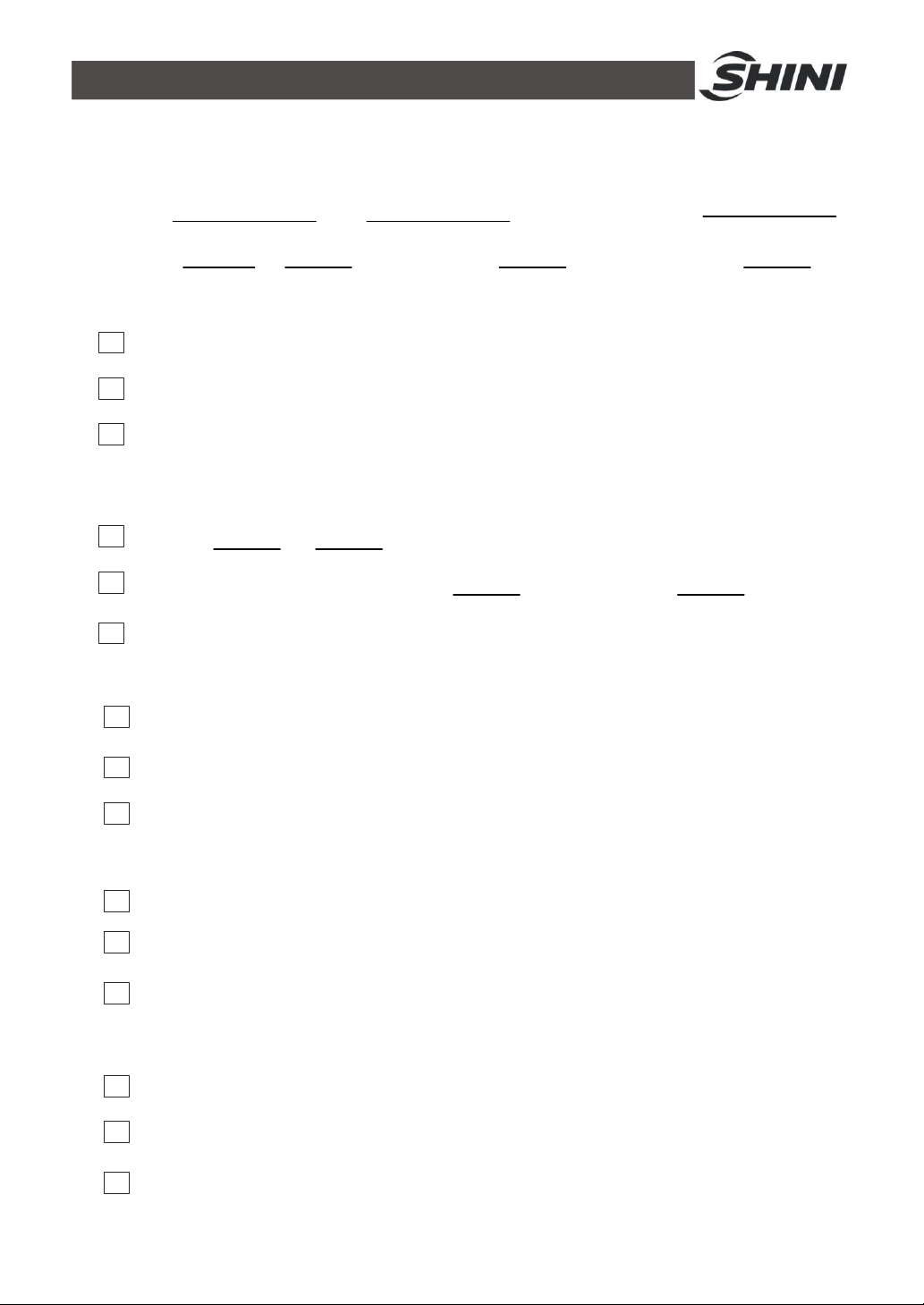
8.5 Maintenance Schedule
8.5.1 About the Machine
Model: SN: Manufacturing date:
Voltage: Ф V Frequency: Hz Total power: Kw
8.5.2 Check after Installation
Check that the conveying hose is correctly connected.
Check that the conveying hose is tightly connected.
Check that the mounting base is tightly fixed.
Electrical Specifications
Voltage: V Hz
Fuse burnt current: One phase A Three-phase A
Check phase sequence of power supply
8.5.3 Daily Checking
Check main power switch
Check filter screen
Check motor performance
8.5.4 Weekly Checking
Check if there are damaged electrical wires
Check if there are loose connections of electrical components
Check if the screws of flange at material inlet are loose or not
8.5.5 Monthly Check
Check the spring lock on the hopper cover is loosed or not.
Check the non-return valve is deformed or not.
Check the performance of magnetic proximity switch/photoelectrical sensor.
40(40)
 Loading...